Announcement:
Electric networks 0.4 kV and substations 6 (10) kV/0.4 kV in calculations of reactive power compensation. Calculation of reactive power compensation in 0.4 kV electrical networks. How to calculate the power of an installation for an electrical network of 0.4 kV.
All electrical networks of 0.4 kV objects, based on the balance sheet boundary, usually determined by the presence or absence of their own 6/10 kV loads, can be divided into 6 (10) kV/0.4 kV substations and TPs connected on the low voltage side, which determines choice of method, methodology for calculating reactive power compensation and choice of power factor correction settings. So, for networks with:
- at 6 (10) kV/0.4 kV substations with a small volume of non-linear loads, compensation on the higher voltage side may be advisable;
- 6/10 kV loads, it must be taken into account that for these loads reactive power must be transmitted from the 6 (10) kV network, i.e. When integrating power factor correction devices on the low voltage side of a 6/10 kV transformer substation, it is necessary to use an individual or group compensation method.
Calculation of reactive power compensation in 0.4 kV electrical networks
When calculating reactive power compensation in 0.4 kV electrical networks, it is necessary to take into account that:
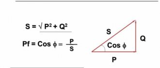
- the real power generated by a compensation installation based on capacitor banks depends on the rated network voltage Un and the voltage at the installation connection point Uin - Qph = (Un/Uin)²*Qpasp, where Qpasp is the nameplate rated power of the installation. For a 0.4 kV network Un = Uin – 1, for 6/10 kV networks Un/Uin = 0.95;
- if there are synchronous motors and/or long overhead lines in the electrical network of the facility, the permissible design power of generation by the installation of KRM, UKRMI, UKM must be reduced when integrating on the side: - voltage 0.4 kV on Qsd - power generated by synchronous motors in the network 0.4 kV (Qsd = α*Qн, where α is the rated (or reference) limit value of the motor overload for reactive power, Qн is the rated reactive power); - voltage 6/10 kV at (0.7*Qsd + Ql), where Ql is the reactive power generated by the overhead (or cable) line, which is equal to U²*Qу*L (U is the rated network voltage, Qу is the specific power of 1 km of cable / overhead line, L – line length);
- power factor correction by integrating KRM, UKRM, UKM, etc. installations is not performed in a 0.4 kV network at the design power of the installation
- the selection of capacitors for installation, a battery or an individual compensation circuit cannot be made only based on the ratio of the total power of nonlinear loads to the power of transformers - a technically competent selection of capacitors is made according to the nature of the loads, the operating mode of the equipment, the intensity of clogging of the network with current harmonics, operating conditions, etc. based on an energy audit and only by specialized specialists who manufacture reactive power compensation installations;
- any calculation calculator on the websites of trading companies and installation manufacturers is indicative, and online calculations, including the calculation of a transformer, installations, can be completely incorrect if: - the calculation calculator or online calculations are based on limited information, for example, according to active and reactive energy only during peak hours, in one of the seasons, without loading characteristics, operating mode, etc.; — the calculation calculator or online calculations initially contain incorrect (not formalized or technically justified) methods;
- a calculation calculator or online calculations, at best, give an after-the-fact idea of the need for compensation, but do not allow one to determine a cost-effective method and means of power factor correction, including the possibility of integrating relatively inexpensive unregulated units or capacitor banks, the presence or absence of the need to use active harmonic filters, etc.
Determination of the equivalent working time of the load in the enterprise power network
Equivalent working time of more than one month (