What to look for and how to increase equipment uptime.
Electric motors are ubiquitous in industry and are becoming increasingly complex, which can often make it difficult to keep them operating at peak efficiency. It is important to remember that the causes of faults in electric motors and drives are not limited to one area of specialization: they can be both mechanical and electrical in nature. And only the right knowledge saves you from costly downtime and extended service life.
The most common malfunctions of electric motors are damage to the winding insulation and wear of bearings, which occur for many different reasons. This article focuses on early detection of the 13 most common causes of insulation failure and bearing failure.
Power quality
Transient voltage
Transient voltages can come from a variety of sources both within and outside the plant. The turning on and off of nearby loads, power factor correction capacitor banks, or even weather events can all create transient voltages on distribution networks. These processes with arbitrary amplitude and frequency can destroy or damage the insulation of electric motor windings. Locating the source of transients can be challenging because they occur irregularly and their effects can manifest in different ways. For example, transients may appear in control cables and will not necessarily cause damage to the equipment itself, but they may interfere with its operation.
Impact: Damage to motor winding insulation leads to early faults and unplanned downtime.
Measurement and diagnostic device: Fluke 435-II three-phase power quality analyzer.
Criticality: high.
Voltage asymmetry
Three-phase distribution networks often supply single-phase loads. Resistance or load asymmetry can cause voltage asymmetry on all three phases. Possible faults may be in the motor wiring, at the motor terminals, as well as in the windings themselves. This asymmetry can cause overloads in each phase circuit of a three-phase network. In short, the voltage on all three phases should always be the same.
Impact: Unbalance causes overcurrents in one or more phases, which cause overheating and insulation damage.
Measurement and Diagnostic Tool: Fluke 435-II Three-Phase Power Quality Analyzer.
Criticality: medium.
Harmonic distortion
Simply put, harmonics are any unwanted additional high-frequency voltage or current fluctuations entering the windings of an electric motor. This additional energy is not used to rotate the motor shaft, but circulates in the windings and ultimately leads to a loss of internal energy. These losses are dissipated as heat, which degrades the insulating properties of the windings over time. Some harmonic distortion in the current waveform is normal for systems powering electronic loads. Harmonic distortion can be measured with a power quality analyzer by monitoring currents and temperatures on transformers to ensure they are not overloaded. For each harmonic, an acceptable level of distortion is established, which is regulated by the IEEE 519-1992 standard.
Impact: Reduced motor efficiency results in additional costs and increased operating temperature.
Measurement and Diagnostic Tool: Fluke 435-II Three-Phase Power Quality Analyzer.
Criticality: medium.
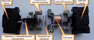
Starter malfunctions
Starter malfunctions are divided into two categories
- mechanical failure or wear
- damage to the electrical circuit
Since the motor shaft spin-up device consists of two electrical elements, damage to the electrical circuit is also divided into two subcategories:
- electric motor malfunction
- Solenoid relay malfunction
Malfunction of the mechanical part of the starter can be repaired by replacing the bearings or bendix.
Failures of the electrical component of the structure are eliminated by replacing the entire blocks, perhaps with the exception of replacing the carbon brushes.
Variable Frequency Drives
Reflections on drive PWM output signals
Variable frequency drives use pulse width modulation (PWM) to control the output voltage and frequency of the motor supply. Reflections occur due to a mismatch between the source and load impedances. Impedance mismatches can occur as a result of improper installation, incorrect component selection, or equipment deterioration over time. The reflection peak in the drive circuit can reach the DC bus voltage level.
Impact: Damage to motor winding insulation results in unplanned downtime.
Measurement and Diagnostic Tool: Fluke 190-204 ScopeMeter®, 4-channel, high-sampling-rate handheld oscilloscope.
Criticality: high.
Standard deviation of current
At its core, standard deviation of current is parasitic currents circulating in the system. The standard deviation of current is formed as a result of signal frequency, voltage level, capacitance and inductance in the conductors. These circulating currents can escape through protective grounding systems, causing a nuisance trip or, in some cases, heating of the winding. The standard deviation of current can be found in the wiring of an electric motor; it is the sum of the current from the three phases at any given time. In an ideal situation, the sum of these three currents should be zero. In other words, the reverse current from the drive will be equal to the current entering the drive. The standard deviation of the current can also be represented as asymmetric signals in several conductors that are capacitively coupled to the ground conductor.
Impact: random opening of the circuit due to the passage of current through the protective grounding.
Instrument for measurement and diagnostics: isolated 4-channel portable oscilloscope Fluke 190-204 ScopeMeter with wideband (10 kHz) current clamps (Fluke i400S or similar).
Criticality: low.
Work overload
Motor overload occurs when it operates under increased load. The main signs of an overloaded motor are excessive current consumption, insufficient torque and overheating. Excessive heat generation from an electric motor is the main cause of motor failure. When a motor is overloaded, individual motor components—including bearings, windings, and other parts—may operate normally, but the motor will overheat. Therefore, troubleshooting should begin by checking whether the electric motor is overloaded. Since 30% of all motor failures are caused by motor overload, it is important to understand how to measure and determine motor overload.
Impact: Premature wear of the electrical and mechanical components of the electric motor, leading to irreversible failure.
Measurement and diagnostic tool: Fluke 289 digital multimeter.
Criticality: high.
Defects in electric motor windings
Loss of one of the phases of the circuit (Star)
Loss of one of the phases of the circuit (Star)
Loss of one of the phases of the circuit (Triangle)
Loss of one of the phases of the circuit (Triangle)
Phase-to-phase fault
Phase-to-phase fault
Interturn closure
Interturn closure
Short circuit to the housing at the exit from the groove
Short circuit to the housing at the exit from the groove
Short circuit to the groove body
Short circuit to the groove body
Short circuit in the circuit
Short circuit in the circuit
Phase damage due to voltage imbalance
Phase damage due to voltage imbalance
Winding damage due to overload
Winding damage due to overload
Winding damage due to jammed rotor
Winding damage due to jammed rotor
Mechanical reasons
Centering violation
Misalignment occurs when the drive shaft is not aligned correctly with the load or the gear that connects them is misaligned. Many experts believe that a flex joint eliminates and compensates for misalignment, however, a flex joint only protects the transmission itself from misalignment. Even with a flexible connection, an off-center shaft will transmit damaging cyclic forces along its length to the motor, causing increased wear on the motor and increasing the actual mechanical load. In addition, misalignment can cause vibration of the shafts of both the load and the electric drive. There are several types of misalignment:
- Angular misalignment: The shaft axes intersect, but are not parallel.
- Parallel offset: The shaft axes are parallel, but not coaxial.
- Compound offset: a combination of angular and parallel offsets. (Note: misalignment is almost always complex, but practitioners consider it as the sum of the displacement components, since it is easier to eliminate misalignment separately - the angular and parallel components).
Impact: Premature wear of mechanical drive components causing premature failures
Impact: Premature wear of mechanical drive components causing premature failures
Measurement and Diagnostic Tool: Fluke 830 Laser Shaft Alignment Tool
Criticality: high
Shaft imbalance
Imbalance is a condition of a rotating part when the center of mass is not located on the axis of rotation. In other words, when the center of gravity is somewhere on the rotor. Although it is impossible to completely eliminate engine imbalance, you can determine if it is outside of acceptable limits and take steps to correct the situation. Imbalance can be caused by various reasons:
- accumulation of dirt;
- lack of balancing weights;
- deviations in production;
- unequal mass of motor windings and other factors associated with wear.
A vibration tester or vibration analyzer will help determine whether a rotating mechanism is balanced or not.
Impact: Premature wear of mechanical drive components causing premature failure.
Instrument for measurement and diagnostics: Fluke 810 vibration meter.
Criticality: high.
Shaft looseness
Looseness occurs due to excessive clearance between parts. Looseness can occur in several places:
- Rotational looseness occurs due to excessive play between rotating and stationary machine parts, such as a bearing.
- Non-rotational looseness occurs between two normally stationary parts, such as between a support and a base or a bearing housing and a machine.
As with all sources of vibration, it is important to be able to identify looseness and correct the problem to avoid damage. You can determine if there is looseness in a rotating machine using a vibration tester or vibration analyzer.
Impact: Accelerated wear of rotating components causing mechanical failures
Measurement and Diagnostic Tool: Fluke 810 Vibration Meter
Criticality: high
Bearing wear
A bad bearing has increased friction, runs hotter, and has reduced efficiency due to mechanical problems, lubrication problems, or wear. Bearing failure can be the result of various factors:
- load exceeding the design load;
- insufficient or incorrect lubrication;
- ineffective bearing sealing;
- violation of shaft centering;
- incorrect installation;
- normal wear and tear;
- induced voltage on the shaft.
When bearing failures begin to occur, this also causes a cascading effect that accelerates engine failure. 13% of engine failures are caused by bearing failures, and more than 60% of plant mechanical failures are caused by bearing wear, so it's important to know how to troubleshoot these potential problems.
Impact: Accelerated wear of rotating components leads to bearing failure
Measurement and Diagnostic Tool: Fluke 810 Vibration Meter
Criticality: high
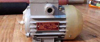
Disassembling a typical asynchronous motor
Since there is a wide variety of designs of electric motors, to disassemble a particular electric motor you need to study its drawings and repair instructions, and watch visual videos.
But in general terms, the designs of electric motors popular in everyday life are similar - there are rolling bearings on the rotor shaft, the outer races of which are pressed into seats on the inner surfaces of the end shields (covers). Design of an asynchronous three-phase motor with a squirrel-cage rotor
The shields themselves are centered using a machined cylindrical edge that matches in size with the groove on the stator casing. The end shields are fixed using bolted connections. When disassembling the engine, its shaft is disconnected from the driven mechanisms and the electric motor is removed from the frame.
Removing the engine from the workplace
After this, it is necessary to remove the mechanical energy transmission element (pulley, gear, flange, etc.) from the shaft. After unscrewing the fastening bolts, use a puller to remove the end shields from the bearings, after which you can carefully remove the rotor.
Bearing puller
The bearings are cleaned, re-lubricated or replaced, the rotor and stator surfaces are cleaned, and the engine is reassembled. There are many bearing removal methods, methods and tools.
Factors associated with improper installation
Loose base
Base is loose Corner base is loose Cause of base A loose fit is caused by an uneven mounting base of the motor or driven component or an uneven mounting surface on which the mounting base is located. This condition can create an unfortunate situation in which tightening the mounting bolts actually introduces new loads and misalignment. A loose support often occurs between two diagonally positioned mounting bolts, as is the case with an uneven chair or table that rocks diagonally. There are two types of loose base:
- Parallel loose base - occurs when one mounting support is located higher than the other three.
- Angular base leak—occurs when one of the mounting supports is not parallel or perpendicular to the mounting surface.
In both cases, a loose base may be caused by irregularities in the mechanism's mounting support or in the mounting base on which the support is located. In any case, it is necessary to find and eliminate a loose fit before centering the shaft. A quality laser alignment tool can determine if the base of a given rotating machine is loose.
Impact: misalignment of mechanical drive components
Measurement and Diagnostic Tool: Fluke 830 Laser Shaft Alignment Tool
Criticality: medium
Piping voltage
Piping tension is a condition in which new loads, tensions and forces acting on the rest of the equipment and infrastructure are transferred back to the motor and drive, resulting in misalignment. The most common example of this is simple motor/pump circuits where something is acting on the piping, such as:
- displacement in the foundation;
- a recently installed valve or other component;
- an object striking, bending or simply pressing on the pipe;
- Broken or missing pipe fixtures or wall fittings.
These forces can cause angular or shearing effects, which in turn cause the motor/pump shaft to move. For this reason, it is important to check machine alignment not only during installation - accurate alignment is a temporary condition and may change over time.
Impact: Shaft misalignment and subsequent stress on rotating components leading to premature failure.
Measurement and Diagnostic Tool: Fluke 830 Laser Shaft Alignment Tool
Criticality: low
Shaft voltage
When the voltage on the motor shaft exceeds the insulating characteristics of the bearing lubricant, breakdown occurs to the outer bearing, causing pitting and groove formation in the bearing raceway. The first signs of a problem are noise and overheating that occurs as the bearings lose their original shape, as well as the appearance of metal chips in the lubricant and increased bearing friction. This can lead to bearing failure after just a few months of operation of the electric motor.
Bearing failure is a costly problem in both motor rebuilding and equipment downtime, so preventing it by measuring shaft voltage and bearing current is an important part of diagnosis. Shaft voltage is only present when the motor is energized and rotating. A carbon brush mounted on the probe allows you to measure the voltage on the shaft as the electric motor rotates.
Impact: Arcing on the bearing surface causes pitting and groove formation, which in turn leads to excessive vibration and subsequent bearing failure.
Instrument for measurement and diagnostics: isolated 4-channel portable oscilloscope Fluke-190-204 ScopeMeter, AEGIS probe with carbon brushes for measuring shaft voltage.
Criticality: high.
Starter
The starter is an electric DC motor. The main purpose of this structural element is to set in motion the connecting rod and piston group to ensure the initial compression of the fuel-air mixture (FA) in the cylinders. To ensure engine starting, spinning the flywheel to a frequency of 50-70 rpm is sufficient.
At this speed of rotation and the normal state of the cylinders, pistons and rings, compression of the fuel-air mixture is ensured to the degree necessary to ignite the fuel assembly and transfer the energy of the ignited mixture to the shoulders of the crankshaft. Then the process occurs independently.
Thus, the electrical device does not directly affect engine starting, but is only an auxiliary unit for the initial spin-up of the crankshaft.
The main purpose of using this electric motor is to eliminate the need for physical force and ensure ease of use of the car.
Four Strategies for Success
Electric motor control systems are used in critical processes in factories. Equipment failure can lead to large financial losses associated with both the potential replacement of the electric motor and its parts, and the downtime of systems that depend on this electric motor. By equipping service engineers and technicians with the knowledge they need, prioritizing work, and performing preventative maintenance to monitor equipment and correct hard-to-find problems, workload-induced failures can often be avoided and downtime costs can be reduced. There are four key strategies to eliminate or prevent premature motor and rotating component failures:
- Record operating conditions, equipment specifications, and operating tolerance ranges.
- Regular collection and recording of critical measurements during installation, before and after maintenance.
- Create an archive of reference measurements for trend analysis and state change detection.
- Graph individual measurements to identify major trends. Any change in the trend line of more than +/- 10-20% (or any other specified amount, depending on the operational characteristics or criticality of the system) should be investigated to determine the cause of the problems.
Types of electrical machine repairs
To prevent malfunctions, maintenance and scheduled repairs of electrical equipment should be carried out according to the approved schedule.
Electrical machine repairs are divided into maintenance (MOT), current, medium and major repairs. The scope of work in each of these types of work is determined by the “Standard Regulations on Maintenance and Repair (MRO) of Electrical Equipment.”
Maintenance
This is to maintain equipment in working order between scheduled repairs. Carried out by maintenance and operational maintenance personnel.
Provides for the following types of work:
- inspection;
- heating check;
- wiping off dirt;
- insulation check;
- identifying faults and eliminating them.
It is carried out according to the approved schedule and during downtime - lunch break, adjustment, tool change.
Maintenance
Maintained in working condition until repaired. Produced on site or in a workshop. Includes:
- complex of maintenance works;
- replacement of failed components - bearings and couplings;
- adjustment and checking of alignment.
Medium renovation
For problems that cannot be eliminated during routine repairs, a medium repair is performed. This produces:
- complete disassembly;
- if necessary, replace bearings;
- repair of housing and shaft;
- impregnation of windings with varnish;
- insulation or replacement of leads
Medium repairs are carried out in specialized workshops and enterprises.
How to find turn-to-turn short circuit
If you notice that a running engine heats up unevenly, that is, one part of the housing is hotter, then this may also indicate an interturn short circuit. But this is not a 100% way.
To search for an interturn short circuit, use a megohmmeter or multimeter and turn the switch to 200 ohms. We put it on each of the windings one by one and check the resistance. If the difference is more than 10-15%, it is better to rewind it.
Current follows the path of least resistance. When some of the turns are excluded from operation, then the resistance on that coil/winding will be lower.
Next, you can disassemble and visually evaluate the coils. It is even possible to identify burnt, melted wires this way. You will have to rewind the loose coil motor.
You can also measure the current on a running electric motor. First, check the voltage and then measure the current. At equal voltage, the current value should not differ by more than 15%.
Uniform stator overheating
In some cases, the active steel of the stator of electric motors begins to overheat, although the load has rated parameters. In this case, heating can be uniform or uneven. In the first case, the reason may be the voltage, which is higher than the rated value, or it may be the fan. The cause of such a malfunction can be easily eliminated - to do this, you need to reduce the load or strengthen the fan motor.
When identifying motor faults, it is also important to pay attention to how the stator windings are connected. Usually it all depends on the value of the rated voltage:
- For low values, a delta connection is used.
- For higher voltages a star connection is provided.
In other words, for a “triangle” it is 220 V, and for a “star” it is 380 V. Otherwise, the power unit may be overloaded, which can lead to its overheating.
Diagnostics
To understand how to repair an asynchronous electric motor, it is necessary to carry out preliminary diagnostics.
Diagnosis of the causes of malfunctions is the key to successful repairs.
If the breakdown did not occur due to an emergency, then the following actions are performed:
- Visual inspection of the electric motor;
- Measurements of clearances in bearings;
- Measuring basic parameters of an electrical installation;
- Checking the integrity of the brush assembly;
- Detection of overheating and intense heating zones.
Principle of operation
During our school years, in physics lessons, we were taught the concept of magnetostriction. Not everyone, however, was interested in it then. Let us now try to return to the topic and briefly outline the essence of the process. First, let's remember how a transformer works.
The figure shows the simplest device, consisting of a primary winding (A), a secondary winding (B) and a core (C) - a magnetic circuit assembled from metal plates or from a material with ferromagnetic properties.
When an alternating voltage is applied to the primary winding (A), a current begins to flow in it, under the influence of which a magnetic flux (F) is formed in the core (C), inducing a current in the secondary coil (B), to which the load is connected. A voltage conversion occurs, the value of which at the output will depend on the ratio of the number of turns of the primary and secondary windings. The frequency will remain unchanged.
Magnetostriction is a physical process of changing the volume and size of a body under the influence of a magnetic flux passing through this body. Materials with pronounced magnetic properties, from which cores for transformers are produced, are subject to changes.
The figure shows the periodicity of the process of compression and stretching of the core during a cycle of changing magnetic flux. Changes in the size of the magnetic circuit lead to air vibrations. Waves are formed that have a frequency in the audio range (50 Hz). This is the same hum that accompanies the normal operation of power transformers. In SMPS (switching power supplies) there is no such noise, since the frequency of the waves generated during the oscillation process is not included in the human audible range.
Increased vibrations
From a technical point of view, such a phenomenon can also be considered a malfunction of the electric motor. Typically, strong vibrations occur due to unbalance of the rotor, coupling or pulley. This phenomenon can also be facilitated by inaccurate alignment of the device shafts and bending of the coupling halves.
The first step is to balance the rotor, for which you need to balance the coupling halves with pulleys. You also need to center the engine. Place the coupling half in the correct position, but to do this, you must first remove it. Find the point of poor connection or break, and then repair the damage.
see also
Comments 21
Am I the only one who saw a centrifugal pump in the classic arrangement of several impellers? They didn’t show the ejector, which is a pity.
I start any starting problems by checking the capacitor, unless of course it is a three-phase motor.
The other day the condenser on my concrete mixer exploded. It’s good that there is something to replace it at home - otherwise the work has become.
It seems that the Chinese capacitors have collapsed and are all smaller than they were before...
I didn’t run around the city, but stopped at the most expensive chipdip store and took what was in stock. 280 rub.
It seems that the Chinese capacitors have collapsed and are all smaller than they were before...
Yes, but there is no choice, everything is made in China, even “American” iPhones, the question is which production facility...
He doesn't look 15 years old, he's in excellent condition. Capacity is a small thing.
What will happen to him? Stands in a corner, puffs))
Over the 15 years of operation of the station, we have had so many pumps at work and almost all of them have been replaced. Either the leaking oil seal was missed, flooded, burned out, or the impeller was damaged by deposits. Well, the load on the equipment leaves its mark.
The load is relatively light. Mostly he works on summer weekends.
99% of the failures of asynchronous units are due to this condenser) but did they at least wash the bearings and fill them with new grease?
Yes, I carried out prevention!
How did you wash the 202s with metal caps? The pump is 15 years old - the seal and the baffle washer between the engine and the industrial plate need to be changed! according to the Conder - we came across this size - inside this case there was a smaller Conder!)))
Prevention is easy. I removed the old grease from the outside, coated it with green loctite, and washed the ejectors. The seals are fine.
outside ? change the bearings! One wedge will give - the automation will not work and the stator will burn out! He's already been playing around! look for yourself - the oil seal costs up to 10 dolars, and rewinding - for such an engine - 50-70 dolars. the plus shaft will rust. if it’s made of black carbon. I’ve had engines come in for repairs that were so hot that the air impeller and the cover simply melted! and the water impeller rarely burned out either.
Noted !
I’ve just been working on fountains and pools for more than 10 years...
outside ? change the bearings! One wedge will give - the automation will not work and the stator will burn out! He's already been playing around! look for yourself - the oil seal costs up to 10 dolars, and rewinding - for such an engine - 50-70 dolars. the plus shaft will rust. if it’s made of black carbon. I’ve had engines come in for repairs that were so hot that the air impeller and the cover simply melted! and the water impeller rarely burned out either.
We need to raise the price tag, otherwise I have these pumps (translated into dollars) for 40 capital (rewinding and mechanics) =-O
We have Donbass... these are the prices. Oil seals also come in different prices, for example, for the Chinese emaux sc series - 20 dollars, retail and krypsol ka series - 60 dollars. This is retail for the importer in Crimea and Ukraine. in Russia the same difference. and rewinding is also different. I rewind in my city in a small private company where personnel work from the “fallen” (khspkz) - even engines that famous workshops in Donetsk refused - they rewind with a bang!
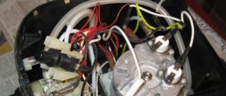
Schematic electrical diagrams, connecting devices and pinouts of connectors
There are 2 types of single-phase asynchronous motors - bifilar (with a starting winding) and capacitor. Their difference is that in bifilar single-phase motors the starting winding operates only until the motor accelerates. Afterwards it is turned off by a special device - a centrifugal switch or a start-up relay (in refrigerators). This is necessary because after overclocking it reduces efficiency.
In capacitor single-phase motors, the capacitor winding runs all the time. Two windings - the main and auxiliary, they are shifted relative to each other by 90°. Thanks to this, you can change the direction of rotation. The capacitor on such engines is usually attached to the housing and is easy to identify by this feature.
It's all in the rotor
If the following characteristic symptoms occur, the cause of the rotor malfunction should be sought in poor-quality soldering of its circuit:
- rotor overheating;
- buzzing;
- braking;
- asymmetrical current readings in phases.
Before you begin to repair the rotor, you should examine how well the soldering of its windings was done. If necessary, it is worth re-soldering, the same should be done with those areas that cause concern.
There may also be cases when the malfunction of the electric motor is due to the fact that the rotor is motionless and open, although the three rings have the same voltage. In this case, the cause of the malfunction most likely lies in the rupture of the wires connecting the rotor to the starting rheostat. As a rule, this is due to wear of the liners, shifting of the bearing shields, due to which the rotor begins to be attracted to the stator. Rotor repair means replacing the liners, as well as adjusting the bearing shields.
In addition, the brushes and commutator may spark or heat up. This can happen for several reasons:
- the brushes have become unusable;
- incorrect installation of brushes;
- the dimensions of the brushes do not correspond to the dimensions of the holder cage;
- poor connection of brushes to fittings.
In this case, it is enough to precisely align the brushes with the holders.