Hello dear readers. In this article we will look at what a fuse is, its structure, types of fuses and different designs.
Any electrical system operates on a balance of supplied and consumed energy. When voltage is applied to an electrical circuit, it is applied to a certain circuit resistance. As a result, based on Ohm's law, a current is generated, thanks to which work is done.
In case of insulation failures, installation errors, or emergency mode, the resistance of the electrical circuit gradually decreases or drops sharply. This leads to a corresponding increase in current, which, when reaching a value exceeding the rated value, causes harm to equipment and people.
Safety issues have always been and will be relevant when using electrical energy. Therefore, increased attention is constantly paid to safety devices. The first such designs, called fuses, are widely used to this day.
Types of fuses
The electrical fuse is part of the operating circuit, it cuts into the cut of the supply wire, must reliably withstand the operating load and protect the circuit from the occurrence of excess currents. This function is the basis for its classification by rated current.
According to the principle of operation used and the method of breaking the circuit, all fuses are divided into 4 groups:
- with fusible link
- electromechanical design
- based on electronic components
- self-healing models with nonlinear reversible properties after the action of supercurrents
Operating principle and purpose of fuses
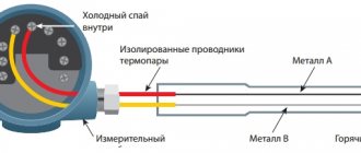
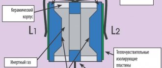
Inside the fuse insert there is a conductor made of pure metal (copper, zinc, etc.) or alloy (steel). Circuit protection is based on the physical property of metals to heat up when current passes. Many alloys also have a positive coefficient of thermal resistance. Its effect is as follows:
- when the current is below the rated value provided for the conductor, the metal heats up evenly, managing to dissipate heat, and does not overheat;
- A large current will lead to heating of the conductor, and a fuse designed for a certain current will be destroyed.
This property is used to melt a thin wire placed in an electrical fuse. Depending on the application, the shape and cross-section of the conductor can be different: from thin wire in household and automotive appliances to thick plates designed for a current of several thousand amperes (A).
The compact part protects the electrical circuit from overload and short circuit. If the permissible current for the network (i.e., rated) current is exceeded, the insert is destroyed and the circuit breaks. Its operation can be restored only after replacing the element. When there is a defect in connected equipment, the fuses will blow as soon as the faulty appliance is turned on, allowing the integrity of the appliance to be maintained and indicating a problem. If a short circuit occurs in the network, the protective device operates in the same way.
Schematic designation
In diagrams and drawings, the PP is designated as follows:
- a rectangle with a horizontal straight line crossing it in the middle. The ends are connected to the circuit;
- according to foreign standards, other graphic designs can be used: according to IEC - a rectangle with designated segments;
- according to IEEE/ANSI - wave.
Types and types of fuses
For use in electrical circuits, different types and varieties of PP are used. Products manufactured in Russia differ in type of design:
- filled with marking PN-2; PPN, NPN, etc.;
- unfilled (PR-2).
The concept of fullness is associated with the presence inside certain types of inserts of a substance that extinguishes the electric arc that occurs at the moment the conductor burns out. The circuit will be opened only after it disappears. Therefore, flasks filled with PP contain quartz sand. Unfilled ones can release gases that extinguish the arc. This occurs when the material of the insert body is heated.
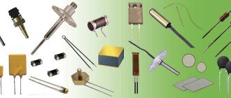
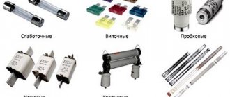
In addition to types, there are different types of PP:
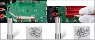
- Low-current ones are used in low-power household appliances with a current consumption of up to 6 A. These are cylindrical inserts with contacts at the ends.
- Fork-mounted PCBs are often installed in cars. The name is due to its appearance: the contacts are on one side of the case and are inserted into the connectors, like a plug into a socket.
- Plug plugs are common electrical plugs for the meter in single-phase networks. The rated current of such inserts is 63 A; they are designed for simultaneous activation of several household appliances. The blown insert in such a fuse is located inside a ceramic housing with a cartridge; 1 contact remains outside, and the other is connected to the contacts of the plug. If the load is exceeded, the part burns out, completely cutting off power to the apartment. The power supply can be restored by replacing the insert with a new one.
- The structure of the tubular PP resembles an insert for plugs, but its fastening is made between 2 contacts. The type of such fuse is unfilled, and the body is made of fiber, which releases gas when heated strongly.
- Blade fuses are designed for a current value of 100-1250 A and are used in networks where a high load is needed (for example, when connecting a device with a powerful motor).
- Quartz, filled with quartz sand, are used in networks with voltages up to 36 kV.
- Gas-generating, collapsible and non-dismountable. When varieties of PSN and PVT are burned, a powerful release of gas occurs, accompanied by popping. PP is used for networks with voltage 35-110 kV. The rated current of such a PP is up to 100A.
Depending on the total load on the network, different types of PP are installed - more powerful ones are installed in special transformer booths; they can withstand the current that meets the needs of a residential area or enterprise. Low-power ones are installed in meters: they protect individual apartments. Old household appliances can also have a PP (low-current) installed, but modern appliances rarely contain these elements.
Technical specifications
| Number of poles | 1 |
| Rated current | 1.6 A |
| Trip characteristic - current curve | WITH |
| Rated operating voltage | 230/400 V |
| Breaking capacity according to EN 60898 | 4.5 kA |
| Width by number of modular distances | 17.8 mm |
| Max incoming cable cross-section | 25 mm |
| Rated DC voltage - DC | 48 V |
| Rated impulse withstand voltage | 4 kV |
| Current limiting class | 3 |
| Frequency | 50 Hz |
| Degree of protection - IP | IP20 |
| Installation type | on DIN rail |
| Climatic performance | UHL4 |
| Release type | Thermal, electromagnetic |
| Scope of application | Industrial and household |
| Total number of poles | 1 |
| Trip time of the release in the short circuit zone tm | 0.1 s |
| Availability of explosion protection | Without explosion protection |
| Mounting rail type | 35×7.5 |
This type of device is the safest, most reliable and affordable.
The fuse link is destroyed instantly under the influence of excessive voltage, providing an effective break in the circuit and protection of the wiring. At normal voltage, the insert heats up, and the heat is dissipated from the outside through the housing parts. The element itself is not deformed.
What happens when the current increases? The temperature of the insert begins to gradually increase as the part offers active resistance. Given the rate of increase in temperature, the element either melts or evaporates.
The main criterion by which a fuse-link is selected for a specific electrical circuit is the time-current parameter. In emergency mode, a quick break in the electrical circuit can prevent the negative consequences of the process.
Selecting a fuse link
The selection of fuses is made taking into account their ratings, time-current characteristics and the total load on the network (the total power of all operating elements). The rated current of the PP is the one that the fuse link can withstand before destruction. This value is indicated on the fuse body (for example, marking 63 A for household plug fuses).
Time-current characteristics are calculated using special graphs. They must be taken into account when connecting electric motors to the network, the starting current of which exceeds the operating current several times. When using several electric motors (in an enterprise), the starting current of the most powerful one is calculated.
The total (maximum) load power of the network is the sum of all operating currents of the devices (indicated in the instructions and on the case). If an electric motor is connected to the network, then its starting current is also taken into account, divided by the coefficient k = 2.5 (for easy starting and squirrel-cage rotor) or 2-1.6 (for hard-to-start or phase-wound rotors).
You can calculate the required nominal value using the formula: I pp>1/k (I total + I start). When calculating, you need to take into account that the rating of the PP must always be greater than the value obtained when calculating by current.
In order not to waste time on calculations, select the rated current of the fuse link according to the table.
| W | 10 | 50 | 100 | 150 | 250 | 500 | 800 | 1000 | 1200 | 1600 | 2000 | 2500 | 3000 | 4000 | 6000 | 8000 | 10000 |
| A | 0,1 | 0,25 | 0,5 | 1 | 2 | 3 | 4 | 5 | 6 | 8 | 10 | 12 | 15 | 20 | 30 | 40 | 50 |
The first line (W) indicates the power of the device indicated on its body, and the second (A) indicates the fuse rating. For an apartment network, you will have to add up the W values of all household appliances and find a suitable number in the table, but it would be better to use circuit breakers.
How to check functionality
The main thing is to determine whether there is a gap. Some types of fuses (often automotive) have a built-in blow indicator. In low-current versions, the wire is visible through the glass flask (if it is broken, then the product is not working).
There are PP options with opaque inserts, cases made of polymers, fiber, ceramics and without indicators. You can diagnose a break with a multimeter:
- Resistance measurement mode (the letter “omega” on the scale, select the minimum value). Probes - to contacts: at “0” or indicators close to it - operability; 1 or infinity sign - the insert is burnt out, there is a gap.
- Dial mode: zero (close to zero) or numbers - operability, if there is a buzzer option, the tester will emit a squeak; 1 - break.
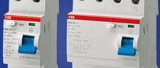
Characteristics of circuit breakers
Circuit breakers are characterized by:
- rated voltage and current of the machine,
- rated current of the release (Inr),
- starting current or tripping current of the machine (Itra),
- limiting circuit breaker current (Ipra).
- own response time (t),
- protective (time-current) characteristic.
The smallest current that causes the circuit breaker to trip is called the starting current or tripping current, and setting the circuit breaker release to a given tripping current is called the tripping current setting.
A separate article on the characteristics of circuit breakers is here.
Power calculation
The fuse link is selected so that it melts before the temperature of the line wires reaches a dangerous level or the overloaded consumer fails. Based on their design features, there are plate, cartridge, tube and plug fuses. The current strength for which the fuse-link is designed is indicated on its body. The maximum permissible voltage at which the fuse can be used is also specified.
This curve is measured experimentally: a batch of identical fuses is taken, which are sequentially burned at different currents. The time after which the insert burns out and the current passing through the insert are measured. Each current corresponds to a certain burnout time of the insert. Based on these data, a time characteristic is constructed.
Probably all of us have seen the ceramic “plugs” that are wrapped in the electric meter panel. Until recently, and sometimes even now, they still serve as protection devices. From personal experience - I have repeatedly encountered this connection scheme - there are two plugs in the panel, one is in the phase wire, the second is in the neutral wire. But what kind of switching scheme is categorically incorrect! Under no circumstances should a fuse be connected to the neutral wire. After all, what happens if it fails - the circuit will break down and will be protected, but consumers will still be under the network potential - the phase is present. And these are issues of electrical safety.
Fuse made in the USSR.
Despite the fact that fuses have served their purpose and become obsolete as protection devices in household bushings, throughout their existence they have adequately performed this function. Fuses, of course, cope with their functions of protecting against excess current consumption or short circuit. However, today, especially in the household sector, fuse links are becoming a rarity.
Plus, these are quite dangerous devices in terms of fire. After all, today many consider themselves electricians, and when the “plug” burns out, some “specialists” install “bugs” from uncalibrated wire. And, sometimes, quite exotic. I described a typical example in the previous review. And what all this entails - you don’t need to go far - look at the chronicle of the emergency on any TV channel. Therefore, it is quite natural that fuse-links have been replaced by more reliable devices - circuit breakers.
Protective characteristics of machines
Circuit breakers may have the following protective characteristics (Fig. 2.6):
- current-dependent characteristic - response time . Such switches have only a thermal release. Rarely used due to insufficient maximum switching capacity and speed;
- current-independent response time characteristic . Such switches have only a current cut-off, performed using an electromagnetic or electronic release operating without a delay or with a time delay;
- limited current-dependent two-stage response time characteristic . In the overload current zone, the switch is turned off with a current-dependent time delay, in the current zone - by a current cut-off with a current-independent, preset time delay (for selective switches) or without a time delay (for non-selective switches). The switch has either a thermal and electromagnetic (combined) release, or an electronic release:
- three-stage protective characteristic . In the overload current zone, the switch is turned off with a current-dependent time delay, in the current zone - with an independent, pre-set time delay (selective cut-off zone), and in close currents - without a time delay (instantaneous operation zone).
The instantaneous response zone is designed to reduce the duration of exposure to currents during close short circuits. Such switches have an electronic release and are used to protect input to package transformer substations and outgoing lines.
The main technical data of some series of machines are given in table. P11.
Semiconductor devices
Due to the development of semiconductor equipment, an additional problem has arisen.
No device operating on a mechanical principle can turn off the electricity supply in time. This also applies to fuses. In modern technology, diodes and transistors are often used. Such devices can only be overloaded for a few tens of milliseconds. Once this threshold is exceeded, the equipment will fail. Semiconductor fuses are designed to minimize the harmful effects of overloads on electronics in inverters, converters, and various soft starters.
Such fuses overheat much faster than fusible metals. But they also have a drawback. During operation, such protection cannot guarantee disconnection of the circuit. The supply of electricity to the device stops, but not completely. Therefore, it is necessary to use a circuit breaker in combination. It is mounted in front of the semiconductor fuse.
Marking
When choosing fuses, it is important to know the protection range. There are only 2 of them: partial and complete. With partial protection, the fuse operates only against short-circuit currents. Full protection also includes overload tripping.
In the code marking, the protection ranges are designated by the letters “a” (partial) and “g” (full). These letters appear first before the numbers indicating the rated current.
In second place are placed English capital letters, which indicate:
- G - universal fuse. Used to protect equipment: transformers, cables, electric motors;
- L - for cables and distribution devices;
- B - protection of mining equipment;
- F - device for low-power circuits;
- M - device for protecting circuits of electric motors and switching devices;
- R - devices for protecting semiconductor circuits;
- S - instantaneous combustion during short circuit and average response time during overload;
- Tr—transformer fuses.
Sometimes only the rated current values are indicated on the inserts. Such fuses are used to protect against short circuits only.
Miniature fuse links are marked in accordance with the requirements of GOST R IEC 60127-1-2005. According to this standard, the rated current and rated voltage are specified.
The following alphabetic symbols are placed in front of the rated current value:
- FF – ultra-fast fuses;
- F – high-speed fuse links;
- M – semi-slow;
- T – slow;
- TT – super slow.
Color marking is allowed. An example of such marking is shown in Fig. 4.
Rice. 4. Color coding of miniature fuses