Connecting consumers to domestic or industrial electrical networks using a cable of less power than necessary can cause serious negative consequences. This will primarily cause circuit breakers to continually trip or fuses to blow. If unprotected, the power wire or cable may burn out. As a result of overheating, the insulation melts and a short circuit occurs between the wires. To avoid such situations, it is necessary to calculate the current by power and voltage in advance, depending on the existing single-phase or three-phase electrical network.
Why do you need current calculation?
Calculation of the current value in terms of power and voltage is carried out at the stage of designing the electrical networks of the facility. The data obtained allows you to correctly select the power cable to which consumers will connect. For current calculations, the value of the network voltage and the full load of electrical appliances is used. In accordance with the magnitude of the current, the cross-section of the cable cores and wires is selected.
If all consumers in a house or apartment are known in advance, then performing calculations is not particularly difficult. In the future, electrical installation work will be greatly simplified. In the same way, calculations are carried out for cables powering industrial equipment, mainly electric motors and other mechanisms.
Selection of electrical appliances
To find out which household appliance is suitable for electrical wiring at home, and for which it is better to use an industrial one, you need to pay attention to its power. This parameter is always written in the operating manual or technical specifications of the device.
You should be wary if the power indicated is more than 1.5 kW, since for such devices you need to use an increased cross-section of the power supply wires. Typically, household electrical appliances have less power.
An exception may be washing machines, electric stoves, and some types of vacuum cleaners. Houses with electric stoves always have separate wiring for them, but to power the washing machine it is better to install a separate wire of increased cross-section.
Next, you should decide on the choice of circuit breaker for groups of electrical consumers. It should be selected specifically for a group, in order to save space in the distribution panel, and to be more free in connecting devices to different sockets. Which groups are better to choose :
- Electric stove;
- Washing machine and water heater;
- Other sockets and lighting.
In homes with electric stoves, the stove will have the highest consumption. Its power is estimated at 10 kW, which with a standard voltage of 220 V means a current consumption of 45 A, cosφ here is 1. The electric stove requires a separate machine, so here it is selected for 50 amperes.
The washing machine also has high current consumption. A standard washing machine consumes 2.5 kW, which corresponds to 12.5 A. Despite the cosφ = 0.8 of the washing machine’s electric motor, it contains a large number of electronics, so for the calculation we take cosφ = 1. The water heater has an even greater power - up to 8 kW . If you intend to use them simultaneously with the washing machine, it is worth taking a machine with a higher amperage, since the total power of these two devices will be 10.5 kW, that is, you need another 50 A machine. It would be better to make two separate machines: 40 A for the water heater, and 15 A - for a washing machine.
The remaining sockets and lighting can be assigned to a separate group. Their total energy consumption is estimated at 1.5 kW, that is, a 10 A machine will be enough for the third group.
Current calculation for a single-phase network
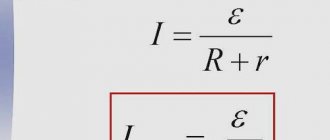
Current is measured in amperes. To calculate power and voltage, the formula is I = P/U, in which P is the power or total electrical load measured in watts. This parameter must be entered in the technical data sheet of the device. U – represents the voltage of the calculated network, measured in volts.
How to find out the current strength, knowing the power and voltage
To answer the question of how to determine current, you need to divide the electrical voltage by the total number of watts. In this case, you can do all the necessary calculations yourself, or you can resort to a special online calculator.
Calculation of power indicator by amperes and watts
You can find out the electricity consumption by the current strength of the resistor by multiplying the former by the resistance, expressed in Ohms. The result is a value expressed in volts multiplied by ohms. It turns out ampere.
Note! If there is no resistance, you need to divide the watt indicator by the current energy, that is, you should divide the watts by amperes and you will get the value of electricity in volts. You can understand the power reading through the amount of electricity with electrical voltage by multiplying the corresponding readings from the device.
Calculation of electricity through electrical power and voltage
Current calculation for a three-phase network
In the case of using a three-phase power supply, the current strength is calculated using the formula: I = P/1.73U, in which P means the power consumption, and U is the voltage in the three-phase network. 1.73 is a special coefficient used for three-phase networks.
Since the voltage in this case is 380 volts, the entire
formula will look like: I = P/657.4.
In the same way as in a single-phase network, the diameter and cross-section of conductors can be determined using a table showing the dependence of these parameters on various loads.
| Diameters of conductor cores (mm) | Conductor core cross-section (mm2) | Copper conductors | Aluminum conductors | ||
| Current (A) | Power, kWt) | Strength (A) | Power, kWt) | ||
| 0,8 | 0,5 | 6 | 2,25 | ||
| 0,98 | 0,75 | 10 | 3,8 | ||
| 1,13 | 1,0 | 14 | 5,3 | ||
| 1,38 | 1,5 | 15 | 5,7 | 10 | 3,8 |
| 1,6 | 2,0 | 19 | 7,2 | 14 | 5,3 |
| 1,78 | 2,5 | 21 | 7,9 | 16 | 6,0 |
| 2,26 | 4,0 | 27 | 10,0 | 21 | 7,9 |
| 2,76 | 6,0 | 34 | 12,0 | 26 | 9,8 |
| 3,57 | 10,0 | 50 | 19,0 | 38 | 14,0 |
| 4,51 | 16,0 | 80 | 30,0 | 55 | 20,0 |
| 5,64 | 25,0 | 100 | 38,0 | 65 | 24,0 |
In some cases, the calculation of current by voltage and power should be carried out taking into account the total reactive power present in electric motors, welding and other equipment. For such devices, the power factor will be 0.8.
Definitions and formulas
Three-phase current generation
The simplest three-phase generator has three identical windings located at an angle of 120° relative to each other. As a result, voltages (phases) are removed from the windings with a phase shift of 120°. These three voltages are independent of each other and their instantaneous values are determined by the formulas:
Here U
p is the peak value (amplitude) of the voltage in volts,
ω
is the angular frequency in radians per second, and
t
is the time in seconds. The voltage induced in winding 2 lags behind the voltage in winding 1 by 120°, and the voltage induced in winding 3 lags behind the voltage in winding 1 by 240°. The figure below shows the vector diagrams and voltage waveforms of the generator:
If the power factor is equal to unity, then in each phase of a three-phase system, voltage, current and power are shifted relative to each other by 120°; the phase sequence in this figure is U₁, U₂, U₃, because U₁ leads U₂, U₂ leads U₃, and U₃ leads U₁.
Advantages of three-phase systems
- Compared with single-phase motors, three-phase motors have a simpler design, high starting torque, high power factor and efficiency, and are more compact.
- The transmission and distribution of three-phase electricity is cheaper compared to single-phase, since it is possible to use wires of a smaller cross-section with a significant reduction in the cost of materials and labor costs.
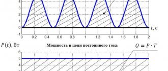
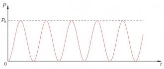
- Unlike the pulsating power of a single-phase system, the instantaneous power of a three-phase system is constant, which ensures smooth rotation and vibration-free operation of motors and other equipment.
- The dimensions of three-phase transformers are smaller than single-phase transformers of similar power.
- A three-phase network can be used to power single-phase loads.
- Three-phase current rectification occurs with a smaller ripple amplitude compared to single-phase current rectification.
Phase sequence
The phase sequence is determined by the time at which the voltage
three phases reach a positive maximum.
The sequence of phases is also called the phase order. In the figure above, the sequence of phases is 1-2-3, since phase 1 reaches a positive maximum earlier than phase 2, and phase 3 reaches a positive maximum later than phase 2. Note that we do not care about the direction of rotation of the generator rotor, because the rotor rotates clockwise can be bypassed and we will observe a counterclockwise rotation. We are only interested in the order of phase alternation of the voltages
generated by the generator.
To determine the phase order in a vector diagram, you need to know that vectors always rotate counterclockwise
. For example, in these three drawings the phase sequence is again U₁, U₂, U₃:
Phase voltage and phase current
Phase voltage is the voltage between each of the three phase wires and the neutral. It is also called phase-to-neutral voltage. The current that flows in the load between the phase wire and the neutral is called phase current.
Line voltage and current
Linear is the voltage between any two phases (lines). The current flowing in each of the lines is called linear.
Symmetrical and asymmetrical systems and loads
In a balanced (symmetrical) three-phase system, the currents in all three phases are equal, and the sum of all currents is zero, so no current flows in the neutral. The amplitudes and frequencies of voltages and currents are the same. They differ only in the phase shift: the voltage in each phase lags behind the previous one by 2π/3, or by 1/3 of a cycle, or by 120°. The vector sum of the three voltages is zero:
The same can be said about currents in a symmetrical system:
If three loads connected to three lines have the same magnitude and power factor, it is also called balanced or symmetrical.
Linear and non-linear loads
In linear loads in AC circuits, voltages and currents have a sinusoidal shape and at any time the current in the load is directly proportional to the voltage across it. Examples of linear loads are heaters and incandescent lamps. capacitors and inductors. All linear loads obey Ohm's law. In linear load the power factor is equal to cos φ
. Read more about nonlinear loads in our Active and Reactive Power Calculator.
In nonlinear loads, the current is not proportional to the voltage and contains harmonics of the fundamental frequency of 50 or 60 Hz. Examples of nonlinear loads are computer power supplies, laser printers, LED and compact fluorescent lamps, electronic motor speed controllers, and many other electrical consumers. Distortion of the shape of harmonic current oscillations leads to distortion of the voltage shape. Ohm's law does not apply to nonlinear loads. In such loads the power factor is not equal to cos φ
.
Delta and star connection
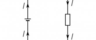
The three windings of a three-phase generator can be connected to the load with six wires, two per winding. To reduce the number of wires, the windings are connected to the load with three or four wires. These two connection methods are called delta (Δ) and star (Y).
In a delta connection, the beginning of each winding is connected to the end of the next winding. Thus, energy can be transmitted through only three wires.
Star (left) and delta (right) connection
In a symmetrical delta connection, the voltages are equal in amplitude, differ in phase by 120° and their sum is zero:
In a symmetrical four-wire star connection system with three identical loads connected to each phase, the instantaneous value of the current flowing through the neutral is equal to the sum of the three phase currents i
₁,
i
₂, and
i
₃, which have the same amplitudes
I
p and are shifted in phase by 120°:
Voltage and power in a symmetrical three-phase load with a star connection
Star connection; I
₁,
I
₂, and
I
₃ are phase currents that are equal to line currents
Apparent power in a three-phase system is the sum of the power consumed by the loads in each of the three phases. Due to the fact that the loads are symmetrical, the same power is consumed in each phase and the total active power in all three phases is equal
Here φ
- phase difference between current and voltage.
Since in a three-phase star connection the phase U
ph and linear rms voltage
U
L are related as
and the root mean square values of the linear and phase currents are equal
The total active power is determined by the following equation:
The total reactive power is equal to
Complex power:
And finally, the total power in three phases is determined by the formula:
Voltage and power in a symmetrical three-phase load with delta connection
Delta connection; I
13,
I
23, and
I
32 are phase currents, and
I
1,
I
2, and
I
3 are linear currents;
in this case I
L = √3∙
I
ph
In a delta connection, there is no neutral conductor and the end of one generator winding is connected to the beginning of the next winding. Phase voltage is the voltage across each winding. Line voltage is the voltage between two phases, that is, also on each of the windings. Thus, the rms voltages on the windings and between the phases are the same, that is, for a delta connection we can write
In a delta connection, the phase currents are the currents flowing through the phase loads. We are considering a symmetrical system, so the phase rms current values I
p1,
I
p2 and
I
p3 are equal in amplitude (
I
p) and differ in phase by 120°:
As we already mentioned, the total power in a three-phase system is the sum of the powers consumed in the loads of the three phases:
where φ
- phase shift between current and voltage.
Since when connected by a triangle, the rms values of the phase U
ph and linear voltages
U
L are equal,
and the rms values of linear and phase currents are related by the formula
active power is determined by the following equation:
The total reactive power is equal to
Complex power:
And the total power in three phases:
Note that the above power equations for star and delta connections are the same. We use them in this calculator.
The fact that these power formulas for star and delta are the same sometimes leads to erroneous conclusions that you can connect the windings of the same electric motor with a star or delta and the power consumption (and current!) will not change. Of course this is wrong. And if we change the star connection to a triangle in the calculator without changing the load, we will see that the power and current consumption will change.
Let's look at an example. The three-phase electric motor is connected in a delta configuration and operates at full rated power at line voltage U
L and line current
I
L. The total power in volt-amperes (VA) is equal to
Then the windings of the same motor were connected in a star. The line voltage applied to each winding decreased by 1/1.73 times, while the mains voltage remained the same. The current in each winding was reduced by 1/1.73 times compared to the current consumed by the delta connection. Total power has also decreased:
Thus, the total power in a star connection is equal to one-third the power in a delta connection for a load of the same impedance. Obviously, the total torque of a motor whose windings are connected by a star will be three times less than the torque of the same motor when the windings are connected by a delta.
In other words, although the new power for a star connection is calculated using the same formula as for a delta connection, other quantities must be inserted into the calculation, namely voltage and current. reduced by 1.73 times (that is, the square root of 3).
Calculation of symmetrical load based on known voltage, current and power factor
To calculate a symmetrical load (the same in each phase) based on known voltage, current and power factor (leading or lagging), the following formulas are used:
Load impedance Z
In polar form:
In complex form:
Calculation of current and power based on known voltage and load
Phase current
According to Ohm's law, we have:
Converting from rectangular coordinates to polar coordinates and vice versa
To convert from rectangular coordinates R
,
X
to polar coordinates
|Z|
,
φ
, use the following formulas:
Impedance triangle
In these formulas R
is always positive, and
X
is positive for an inductive load (current lags voltage) and negative for capacitive load (current leads voltage).
Conversion from polar coordinates r
,
φ
into rectangular coordinates
x
,
y
, is performed according to the formulas:
Active Rph and reactive Xph load resistance
Impedance of capacitor and inductor
Parallel load RLC
Parallel RLC connection
To calculate, use our Parallel RLC Circuit Impedance Calculator.
Serial Load RLC
RLC serial connection
To calculate, use our RLC Series Impedance Calculator
For more information about RLC loads, see our impedance calculators:
- Parallel RC Circuit Impedance Calculator
- Parallel LC Circuit Impedance Calculator
- Parallel RL Circuit Impedance Calculator
- RC Series Impedance Calculator
- Series LC Circuit Impedance Calculator
- Serial RL Circuit Impedance Calculator
Origin of the unit of measurement kilowatt/hour
The intensive study of electricity by European scientists began around the 17th century, at which time fundamental discoveries were made that marked the beginning and development of such a science as electrical engineering. Scottish engineer, mechanical inventor (1736–1819) James Watt introduced into use the first unit of power - horsepower.
Portrait of James Watt:
In 1782, the British Association of Engineers assigned the scientist's name to the unit of power meter - Watt. It must be borne in mind that in Russian the English letter “W” has a double reading, like “V” or “Ua”. Therefore, we read the name of the inventor as Watt, and the unit of measurement is Watt. In 1889, the unit of measurement gained worldwide recognition. Only in 1960, “Watt” officially entered the international SI system as a power meter for any type of energy, be it thermal, mechanical or electrical.
The energy consumption consumed over a certain period of time is measured in W/h. To reduce the number of symbols when indicating the power consumption of an electrical appliance, a unit such as kilowatt/hour - kW/h (1000 Wh) was introduced into use.
Definition
Power is a scalar quantity. In general, it is equal to the ratio of work performed to time:
P=dA/dt
In simple words, this value determines how quickly work is completed. It can be designated not only by the letter P, but also by W or N, and is measured in Watts or kilowatts, which are abbreviated as W and kW, respectively.
Electrical power is equal to the product of current and voltage or:
P=UI
How does this relate to work? U is the ratio of work to transfer a unit charge, and I determines how much charge passed through the wire per unit time. As a result of the transformations, a formula was obtained with which you can find the power, knowing the current strength and voltage.
Formulas for DC circuit calculations
The easiest way to calculate the power is for a DC circuit. If there is current and voltage, then you just need to perform the calculation using the formula given above:
P=UI
But it is not always possible to find power by current and voltage. If you don't know them, you can determine P by knowing the resistance and voltage:
P=U2/R
You can also perform the calculation knowing the current and resistance:
P=I2*R
The last two formulas are convenient for calculating the power of a section of a circuit if you know the R of the element I or U that falls on it.
Calculation of consumer power
First of all, you need to establish in advance the amount of electricity consumed. To do this, the power of all consumers in the house is summed up. This includes high-power equipment, common household appliances and lighting fixtures. For some owners, this list may be supplemented with warm electric floors.
All necessary information can be found in the technical data sheet, which is attached to each device. Some devices are marked accordingly. The most powerful units come first, and then all other equipment, as power decreases.
For calculations, take an automatic washing machine with a power of 2600 W, an electric water heater - 1900 W, an iron - 1500 W, a vacuum cleaner - 1000 W, a microwave oven - 800 W, a computer and office equipment - 600 W, lighting fixtures (with economy lamps) - 400 W , refrigerator – 300 W, TV – 100 W. The final result is 9200 W and must be converted to kilowatts. To do this, 9200 W is divided by 1000, resulting in 9.2 kW, which will be the estimated electricity consumption.
One phase can handle this power, but in private homes more powerful equipment is installed, for which it is better to use 380V networks. In this case, the uninterrupted functioning of heating and water heating boilers, pumps, electric motors and other units is guaranteed.
Example of calculating total power for an electric motor
The power of electric motors can be useful or mechanical on the shaft and electrical. They differ by the coefficient of performance (efficiency), this information is usually indicated on the nameplate of the electric motor.
From here we take the data to calculate the connection in a triangle to Ulinear 380 Volts:
- Pshaft = 160 kW = 160000 W
- n=0.94
- cosФ=0.9
- U=380
Then you can find the active electrical power using the formula:
P=Pon the shaft/n=160000/0.94=170213 W
Now we can find S:
S=P/cosφ=170213/0.9=189126 W
It is this that needs to be found and taken into account when selecting a cable or transformer for an electric motor. This completes the calculations.