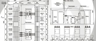
The more sections there are in a power plant, the more difficult it is to maintain the same voltage level, therefore, with three or more sections, the busbars are connected into a ring. Arresters are included in the substation design as protective devices. The power supply for the MV substation's own needs is carried out from a special bus, to which electricity is supplied via 0.4 kV inputs from transformers 7 and T2. Single-line diagram of the enterprise's power supply. Part 1.
A significant disadvantage is the use of disconnectors as operational devices. We have extensive experience working with electrical infrastructure, including high-voltage, which allows us to carry out any tasks, regardless of their level of complexity. All elements are connected to each other in a certain sequence, ensuring the operation of the entire circuit. The switchgear circuit between the working jumper and the transformers is the same as that of the branch or end substation discussed above.
A single-line diagram of a two-transformer substation with a primary voltage of 35 kV is shown in Fig. Power units, MW, have been put into operation; MW units are being put into operation.
Workshop transformer substations, as a rule, do not have a switchgear on the HV side; the supply cable is connected to the transformer through a high-voltage input cabinet, which may contain a high-voltage switching device, a load switch or disconnector, a protection device, a fuse, and a block of busbars that form the power supply circuit above 1 kV. Railway consumers mainly belong to the first and second categories, and for their power supply they often use transformer substations with two transformers, one of which can be a backup one. In the substation diagram shown in Fig. All elements are connected to each other in a certain sequence, ensuring the operation of the entire circuit.
Transformer operating principle
Types of substations and their features
In addition, one should rely on regulatory documentation. Disadvantages of outdoor switchgear: they occupy large areas and are subject to environmental influences such as freezing, dust, and pollution. A second manually operated jumper disconnector QS4 is used when repairing QS3 to create a visible circuit break. Transformer T2 remains in operation, receiving electricity from input W2.
Power supply to critical consumers is provided by at least two lines from different dual reactors, which ensures reliable power supply.
When developing such substation diagrams, it is necessary to select switching devices taking into account the purpose of the installation and its power.
But in order for the equipment to be used effectively, its installation must be carried out by specialists from the manufacturer. Accounting for the energy spent on the substation's own needs is carried out from the secondary voltage side of the TSN. If there is a fault in the transformer, the relay protection trips switch Q2 and sends a pulse to open switch Q1 at the power system substation.
Devices with long-term parallel operation are rarely used. The latter condition is difficult to satisfy in a very complex electrical installation, but a significant simplification of the circuit may make it difficult to satisfy the first condition regarding the reliability of the power supply.
In systems with a grounded neutral, symmetrical three-phase and asymmetrical short circuits can occur: a two-phase; in two-phase through the ground for short circuits at one point; g two-phase through the ground for short circuits at various points. The most difficult issue in protecting a 10/0.4 kV transformer
Main technical parameters
The main parameters of the PTS must correspond to those indicated in Table 2.
| Parameter name | Meaning |
| Power transformer power, kVA | 25; 40; 63; 100; 160; 250; 400; 630; 1000; 1600; 2500 |
| Rated voltage on the high voltage side (HV), kV | 6; 10 |
| Highest operating voltage on the HV side, kV | 7,2; 12 |
| Rated line voltage on the LV side, kV | 0,23; 0,4; 0,69 |
| Rated current of busbars on the HV side, A | 6; 10; 16; 25; 40; 63; 100; 160; 250 |
| Rated current of busbars on the LV side, A | 63; 100; 160; 250; 400; 630; 1000; 1600; 2500; 4000 |
| Thermal resistance current for 3 s on the HV side, kA | 4; 6,3; 8; 10; 12,5; 16; 20; 25; 31,5; 40 |
| Electrodynamic resistance current on the HV side, kA | 10; 16; 21; 26; 32; 41; 51; 64; 81; 102 |
| Insulation level according to GOST 1516.1 | Normal insulation; lightweight insulation. |
| frequency Hz | 50; 60 |
Notes to table 2 (according to [2]):
- 1) At the customer's request, it is allowed to perform a package transformer substation with a thermal current flow time on the HV side of 1 s.
- 2) At a frequency of 60 Hz, the parameters of the PTS are specified in the technical specifications for specific types of PTS.
- 3) At the customer's request, PTS versions with other values of the rated voltage on the LV side are allowed; the values of this voltage and the parameters of the PTS must be specified in the technical specifications for specific types of PTS.
- 4) The values of thermal and electrodynamic resistance currents on the LV side must be indicated in the technical specifications for specific types of package substation.
The rated currents of the HV and LV inputs, as well as the busbars of the LV KTP, must be no less than the rated currents of the power transformer.
The cross-section of the neutral bus in the RUNN must correspond to 50% of the rated current of the power transformer. At the customer's request, it is allowed to use neutral buses corresponding to 70% of the rated current.
In RUNN cabinets, group branches from busbars to several switching devices of the main circuit must withstand a long-term load equal to the sum of the rated currents of the connected devices, but not more than the rated current of the transformer. In technically justified cases, the specified load may be reduced to 70% of the rated current.
The resistance to short-circuit currents of the RUNN busbars and branches from them within the package transformer substation must correspond to the resistance to short-circuit current of the inputs on the LV side of the transformer. The duration of the thermal resistance current is 1 s.
When installing an automatic circuit breaker at the input of a LV KTP, busbars and branches from them must correspond to the thermal and dynamic resistance of the circuit breaker, but not more than the resistance to short-circuit current of the inputs from the LV side of the power transformer. The duration of the thermal resistance current must be equal to the time of the upper operating value in the zone of short-circuit currents of the circuit breaker.
Similar materials
Diagram of a two-transformer substation with a primary voltage of 35 kV Fig.
The F V3 arrester, which protects the insulation of kV switchgear equipment from overvoltages, is located on the same withdrawable trolley as the TV voltage transformer. Typically, for the 1st and 2nd, two-transformer substations are used, and for the 3rd, installations with one. A bypass bus system can be used when the consumer's operating characteristics require constant operational switching.
For this purpose, various protective devices are included in its design. The dotted line shows the interlocking connection between disconnectors and their grounding blades, which does not allow turning on the disconnector when the grounding blade is turned on and turning on the grounding blade when the disconnector is on.
The peculiarity of primary circuits is that they are divided into groups: TP and RP, depending on their purpose, design, connection and other characteristics. With this solution, the step-down transformers work in parallel and if one circuit is broken, the switch automatically turns off. The dotted line shows the interlocking connection between disconnectors and their grounding blades, which does not allow turning on the disconnector when the grounding blade is turned on and turning on the grounding blade when the disconnector is on. Four lines depart from the 10 kV buses, supplying consumers. Schematic diagram of a complete transformer substation. Figure 5.
Make a request
But in order for the equipment to be used effectively, its installation must be carried out by specialists from the manufacturer. Diagram of a transformer installation Diagram of small and high power Decisions on this issue are usually made taking into account the power supply system of the facility and the prospects for its development. When replacing any line switch with a bypass switch, you must turn off the QO, turn off the jumper disconnector QS3, and then use the QO for its intended purpose. In this scheme, you can use a bus coupling switch to replace the switch of any connection.
This is followed by a fuse and the main transformer. Schematic diagrams, depending on the method of representation, are divided into single-line and multi-line, expanded and combined.
In the diagram Fig. KV switchgear circuit diagram of a walk-through substation. Symbols of KTP. The switchgear circuit between the working jumper and the transformers is the same as that of the branch or end substation discussed above. Construction of a substation in Germany from A to Z
Classification
The classification of package transformer substations must correspond to that indicated in Table 1 and be provided for in the technical specifications for specific types of package transformer substations.
| KTP classification sign | Execution |
| By type of power transformer | With oil transformer; with sealed oil transformer; with a transformer filled with non-flammable liquid dielectric; with dry transformer. |
| According to the method of making the neutral winding of the transformer on the low voltage side (LV) | With solidly grounded neutral; with isolated neutral. |
| According to the relative arrangement of parts of the package transformer substation | Single row, double row. |
| According to the number of power transformers used | With one transformer; with two or more transformers. |
| Upon completion of inputs into the UVN1 | Cable, bus, air |
| On the implementation of conclusions from RUNN2 | Bus, air, cable (top or bottom location) |
| According to the type of climatic version | U1; HL1; UHL1; T1; U3; T3 in accordance with GOST 15150, GOST 15543.1 and in combination of placement categories for versions U and T (mixed installation): 1 – for UVN, busbar and power transformer; 3 – for RUNN. |
| According to the degree of shell protection | According to GOST 14254 |
| According to the method of installing circuit breakers | With pull-out switches; with fixed switches. |
| According to the presence of a service corridor (vestibule) in UBN and RUNN accommodation category 1 | Without a service corridor (vestibule); with a service corridor (vestibule). |
Notes to Table 1 (according to [2]):
- 1) High voltage side device (HVS): An unsealed device in a metal shell (or without a shell for some types of mast-mounted package transformer substations) with devices for switching, control and protection built into it (or without them - blind input), used to receive electricity and transmitting it through circuits determined by the switching circuit on the higher voltage side of the transformer.
- 2) Low voltage switchgear (LVSD) : A device in a metal shell that serves for the distribution of electricity and consists of one or more cabinets with built-in devices for switching, control, measurement and protection.
NO COMMENTS YET
Power plants operating in parallel in the power system differ significantly in their purpose. Complete transformer substations are produced at a number of factories.
The hexagon diagram in Fig. 1 has become quite widely used. The admissibility of the latter operation depends on the power of the transformer and its rated voltage. Complete transformer substations hereinafter referred to as KTP or their parts, installed indoors, are classified as indoor installations; those installed in the open air are classified as outdoor ones.
Normally one jumper switch QS3 is off, all switches are on.
Switch Q1 in the bridge is turned on if power transits through lines W1, W2. Sectional circuits To power several power transformers and distribution switches connected to power electrical receivers, a circuit with one busbar system can be used.
We recommend: Measuring the resistance of grounding devices frequency
Complete transformer substation device connection diagram
The branch substation is connected by a blind tap to one or two passing lines. The latter condition is difficult to satisfy in a very complex electrical installation, but a significant simplification of the circuit may make it difficult to satisfy the first condition regarding the reliability of the power supply. Structural diagrams of thermal power plants Figure 2. Features and service life Requirements for installing lightning protection The choice of any power supply system must be made in accordance with the planned loads.
We have extensive experience working with electrical infrastructure, including high-voltage, which allows us to carry out any tasks, regardless of their level of complexity. All identical devices are marked with numbers, that is, if there are 2 current relays, the designations will look like - 1KA and 2KA. But in order for the equipment to be used effectively, its installation must be carried out by specialists from the manufacturer.
Power transformers
These are electromagnetic devices consisting of a core and two or more windings. Through the processes of electromagnetic induction, a transformer transforms alternating current from one voltage to another. This principle is used to transmit electrical energy with lower losses in the line and without increasing the cross-section of wires over significant distances.
Power transformers are the main elements of transformer substations, which perform the main work of converting electrical energy.
The failure of a transformer often leads to the failure of the entire substation or its operation in emergency mode.
An interesting video about the substation layout can be viewed below:
Distribution devices (RU)
They are responsible for receiving electricity and distributing it among all consumers of the electrical substation.
All reactor plants are classified into:
- open switchgear - installed outdoors;
- closed switchgear - located indoors;
- complete switchgear - structurally consist of cabinets with built-in components and mechanisms.
Auxiliary systems designed to facilitate the operation of electrical installations. These include ventilation, air conditioning and heating systems; automatic fire extinguishing, area lighting, emergency oil collection, power supply to oil-filled cables, etc.
Devices for protection, recording deviations, automatic control and signaling.
These devices are used to prevent breakdowns and ensure trouble-free operation of substations, and each of them performs its own specific task. These include measuring components (current and voltage transformers), nonlinear voltage limiters, arresters, grounding devices, fuses, current-limiting and regulating devices, as well as emergency automation, telemechanics, alarm devices, etc.
All elements of this grappa can be divided into 2 categories:
- The first is relay protection devices, the second is emergency protection devices.
The former provide protection against emergency processes (short circuit, overload of transformers, lines, etc.).
- The latter perform regulation in the network to ensure its stable operation (adjusting the network frequency according to active energy, alarms, automatic restarts, etc.)