Purpose and where to use
The use of disconnectors in the energy sector to break circuits is dictated, first of all, by safety considerations. They are used to make connections to contact networks for supplying current from supply lines. These mechanisms also serve to safely change the interconnection patterns of circuit sections.
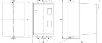
Figure 1 shows a section of a line with high-voltage disconnecting devices.
Figure 1. Line section with high-voltage disconnectors
The switching mechanisms under consideration have two important qualities that allow you to control the switching process:
- The ability to visually monitor the position of moving contacts at disconnection points.
- The absence of a mechanism allowing the possibility of free (arbitrary) release. The use of manual drives ensures that the specialist performs the planned operation of de-energizing or connecting the electrical network at the right time.
This design of the disconnector allows maintenance personnel to quickly assess the condition of the working parts of the switching mechanism before switching on, as well as visually monitor the position of the contact knives in a specific situation. Disconnectors always operate using high voltage switches, both outdoors and indoors.
Such devices can be used to switch transformers operating at no-load, as well as to disconnect lines with circulating pickup currents. With appropriate shunting devices, it is possible to disconnect live electrical circuits or turn off low-power transformer load currents. In this case, an arc discharge is always observed at the initial stage of shutdown or before switching on, when the contacts approach the breakdown distance.
The arcing time is reduced by the presence of contact springs. An exception is the class of load switches, the design of which includes autogas arc extinguishing devices - VNA. Such switches can be used as high-voltage disconnectors, which are used for switching sections of circuits up to 10 kV. (Fig. 2).
Figure 2. High-voltage load switch VNA
Main Applications
High voltage circuit disconnectors are used in many applications. With their help they serve:
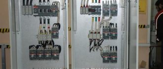
- networks of complete transformer substations, including mobile transformer substations;
- family of complete switchgears KRU and KRUN;
- capacitor units;
- prefabricated chambers designed for one-sided maintenance;
- Main switchboards, input and distribution cabinets and other equipment.
The ability of three-pole and single-pole disconnectors to switch charging currents of overhead wires and cable lines, turn on and off induction currents of power transformers, cut off equalizing currents, and disconnect circuits with small load currents makes these devices indispensable in various power systems.
The areas of application of high-voltage disconnectors are regulated by PTEEP. The rules allow their use in networks of 6 - 10 kV, to switch on or off load currents up to 15 A or equalizing currents up to 70 A.
Technical data of internal disconnectors
| Disconnector series | Voltage, kV | Rated current, A | Standardized parameters for through short-circuit currents, kA | |||
| Electrodynamic withstand current | Thermal current | |||||
| nominal | greatest | 4 s for main knives | 1 s for grounding blades | |||
| RV | 6 | 7.2 | 400 630 1000 | 40 50 80 | 16 20 31.6 | — |
| RV, RVO, RVF | 10 | 12 | ||||
| RVZ | 400 630 1000 | 40 50 80 | 16 20 31,5 | 16 20 31,5 | ||
| RVFZ | 10 | 12 | 630 | 60 | 20 | 20 |
| RLVOM | 1000 | 80 | 31,5 | 31,5 | ||
Design and principle of operation
The creation of a high-voltage disconnector was driven by the need for a switching mechanism capable of providing a safe and visually observable break in high-voltage energized circuits. The design of such a device is based on high reliability of contacts, ensuring the circuit is closed and opened in all weather conditions.
The design of the high-voltage disconnector does not provide for the presence of spark-extinguishing elements. Therefore, in order to prevent the formation of a high-power electric arc that can destroy contacts, the devices are connected in series with high-voltage load switches. Before disconnecting the desired line, use a switch to turn off the load.
The disconnector design consists of a rigid load-bearing frame on which the following elements are mounted:
- a system of fixed insulators located on each side of the break for each phase wire;
- static contacts and contact knives that provide circuit closure and opening;
- mechanism for controlling moving contacts (knives);
- blocking elements.
Disconnectors intended for switching circuits whose voltage exceeds 110,000 V, consist of two contact movable half-blades, separated in opposite directions. The distance between the separated contacts is quite large, which eliminates the breakdown of this space in cases of unauthorized activation of the switch.
Depending on the purpose, the devices in question can be three-pole or single-pole. Three-pole disconnectors have three pairs of contacts. In a single-pole disconnector there is only one pair: a fixed contact and its contactor - a contact knife.
An example of a three-pole disconnector is shown in Figure 3.
Figure 3. Three-pole switch with vertical rotation of knives
Despite the fact that the radios operate with the load disconnected, the possibility of the presence of dangerous induced or capacitive currents cannot be excluded. In order to ensure complete safety for personnel, grounding blades are used, which are mounted on one platform and can perform their intended protective function only after the load switch is disconnected and the contacts connecting the serviced area to the live line are disconnected. Otherwise, a short circuit occurs between the grounded wires.
In order to eliminate damage caused by grounding blades as a result of accidental supply of rated currents, many models are equipped with locking mechanisms. The mechanisms block the movement of the knives when the grounding device is not removed or when the load is on. Most often, mechanical locking is used, but there are also electromagnetic and even hydraulic locking mechanisms. There are models with combined blocking elements.
Fuses
What are fuse switches?
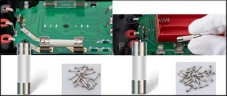
A fuse is a device that, by melting one or more of its parts having a specific design and size, opens the circuit in which it is connected, interrupting the current if it exceeds a specified value for a certain time. The fuse includes all the parts that make up the finished product.
The fuse is the weakest part of the protected electrical circuit, tripping in emergency mode, thereby breaking the circuit and preventing the subsequent destruction of more valuable elements of the electrical circuit by high temperatures caused by excessive current values.
The first fuses began to be used at the end of the 19th century. Since then, their essence has not changed, only the production technology and the quality of their work have changed, both through the selection of materials from which they are made, and by changing the design.
It should be noted that the terms fuse and fuse link have significantly different meanings in modern electrical standards.
Operating principle of a fuse
The so-called fuse is used as a protective element in the fuse. a fuse-link that is located inside a cartridge filled with an arc-extinguishing medium that intensively absorbs heat (quartz sand), for example fuses of the PN-2 or PC types, or without filling, sometimes the autogas principle is used in fuses, when the thermal action of the arc leads to the release of arc-extinguishing gases from the structural elements of the cartridge (fuses of the PR-2 type have this arc extinguishing principle: when an arc occurs, gases are released from the fiber body of the fuse).
The fuse link is made with powerful fuses into plates with cutouts that reduce the cross-sectional area of the insert, while in the nominal mode, excess heat from narrowed places due to thermal conductivity manages to spread to the wide parts and the entire insert has almost the same temperature. When overloaded, the heat does not have time to be completely redistributed throughout the entire volume of the insert and it melts in the hottest place. During a short circuit, the process is so intense that there is practically no redistribution of heat and the insert burns out in several narrowed places.
For faster operation of the fuse (in high-speed fuses), special designs are used (they give the fuse link a special shape), in which the disconnection of the circuit in the fuse at high currents occurs not by melting the insert, but by breaking it by electrodynamic forces (sometimes, to speed up the operation, the fuse link is additionally loaded force of the tensioned spring). To accelerate the melting of the insert, the phenomenon of the metallurgical effect is also used; this solution is usually used in fuses with inserts made of a number of parallel wires (for example, in PC-type fuses).
Some fuse designs use inserts with variable wire cross-sections (PKT type fuses for currents up to 7.5 A): different burnout times for individual sections lead to a reduction in overvoltages when the fuse trips.
An important characteristic of any current protection, incl. and the fuse is time - a current characteristic, usually described in the form of a graph; the current is plotted along the abscissa axis, most often in relative units (the rated current of the fuse-link is taken as a unit), and the response time is plotted along the ordinate. It should be borne in mind that the characteristic of each fuse (even from the same batch) has its own time - current characteristic, which is indicated in the catalog for each type of fuse as a “spread of characteristics zone”, which is guaranteed by the manufacturer.
In this case, it is necessary to keep in mind the difference between the rated current of the fuse and the rated current of the fuse link:
The rated current of a fuse is the current for which the fuse holder is designed.
The rated current of a fuse link is the current for which the fuse link is designed.
In a given size of fuse holder, several inserts with different rated currents can be installed, with the largest one in the rated series usually equal to the rated current of the fuse holder.
Some types of fuses (for example, PCs) have an operation indicator in the form of a spring-loaded pin; when the fuse-link burns out, the indicator pin is ejected by a spring from the fuse body, indicating that the fuse has tripped. Sometimes this pin presses on a special signal contact, sending a signal that the fuse has blown through the telemechanics circuits.
Basic requirements for fuses
The following requirements apply to fuses:
- The time-current characteristic of the fuse should be lower, but as close as possible to the time-current characteristic of the protected object.
- In the event of a short circuit, the fuses must operate selectively.
- The response time of the fuse during a short circuit should be as short as possible, especially when protecting semiconductor devices. Fuses must operate with current limitation.
- The fuse characteristics must be stable. Variations in parameters due to manufacturing deviations should not interfere with the protective properties of the fuse.
- Due to the increased power of installations, fuses must have a high breaking capacity.
- Replacing a blown fuse or fuse link should not take much time.
In industry, fuses of the PR-2 and PN-2 types are most widely used.
Fuse design
All fuse links, regardless of design features, include two main elements:
- fusible element - a conductive element made of metal, an alloy of several metals or specially selected layers of several metals;
- body - a mechanism or system for attaching a fuse element to contacts that ensures the inclusion of the fuse as a whole, as a device, in an electrical circuit.
Fuse-link bodies are usually made of high-strength varieties of special ceramics (porcelain, steatite or corundum-mullite ceramics). For fuse-link housings with low rated currents, special glass is used. The fuse body usually serves as a base part on which a fuse element with fuse contacts, an operation indicator, free contacts, devices for operating the fuse and a rating plate are mounted. At the same time, the housing performs the functions of an electric arc extinguishing chamber.
Principle of operation
Connection or disconnection of the switched electrical circuit is ensured by turning the contact knives. Depending on the design, the moving contacts can be rotated vertically or horizontally. The drive that imparts force to the rotating mechanism is a rod with a handle, with the help of which the operator controls the contact knives. The drive handles are mounted directly on the supports under the disconnector.
Manual control is used mainly on overhead lines up to 6 kV. Knives on lines of 110 kV and above are controlled by electric drives using metal cabinets located at a safe distance.
Worm drive PCH-50M
The weight of disconnectors for currents of more than 4000 A exceeds 100 kg, and it is quite difficult to operate them using a manual drive.
In this case, a worm gearbox is used to enhance the operator’s muscular strength. The most common model with such a gearbox is the PCh-50M worm drive.
The drive consists of the following main components:
- Main worm gearbox
- Lever for controlling the disconnector rod
- Actuator position indicator lever with block lock
- Handle mounted on the worm shaft
The worm drive greatly facilitates the operation of the disconnector, but its cost is comparable to the cost of the disconnector itself. Therefore, the need to use a worm drive has to be weighed.
FIND OUT PRICE
Send a request in any form by email. During the day we will prepare an offer for you with cost and delivery time.
Or just call us at +7 910-973-00-28 Send a request...
Classification
The domestic industry produces high-voltage disconnectors of various types. They can be classified according to the following criteria:
- by number of poles;
- type of contact knife (rotary, chopping, swinging);
- installation location (open space or room);
- by control method: manual (using an insulating rod or levers), electromechanical, hydraulic, pneumatic.
In addition, devices differ in rated voltage and rated current for which they are designed. Products come with grounding switches (disconnectors RVZ, Fig. 4), with figured knives (RVF) and others.
Figure 4. RVFz 1063
The type of device can be determined by its designation.
The letters indicate:
- P – type of product, in this case a disconnector;
- N – external;
- G – horizontal installation;
- L – linear;
- Z – disconnector with grounding blades. The numbers 1, 2... indicate the number of grounding conductors;
- D – with two support-insulating columns;
- The numbers 10, 35, 110, 220 mean the rated voltage in kilovolts.
For example, RV is an internal disconnector, and the abbreviation RLND means that this is a linear type of device with two support-insulating columns for outdoor use.
Short circuits
What is a short circuit?
A short circuiter is an electrical device designed to create an artificial short circuit to ground in power supply networks, in the event of internal damage to the power transformer in the circuit of which, on the high voltage side, it is installed in pairs with a separator. With such a short circuit, the action of linear protections at the supply substations de-energizes the overhead line, the damaged transformer is disconnected from the network by disconnecting the separator, and the line is put into operation by the action of automatic reclosure.
In 110-220 kV networks, short circuiters have one pole, in 35 kV networks - two. The movable knife is activated by the action of the charged closing springs of the short circuit.
Device
Structurally, the short circuit is similar to the ground electrode, but due to the powerful contact system it can be switched on for a short circuit.
Short circuiters are devices of the vertical-cutting type, consisting of a base, an insulating column, a fixed contact with a terminal for connection to a power line and a grounding blade, at the end of which a removable contact plate is attached. At the base of the short-circuit contactor there is a shaft mounted in bearings, two engaging springs with tension adjustment connected to the base and levers of the short-circuit contactor shaft, as well as a hydraulic buffer.
The normal position of the short-circuiter is open. In this case, the knife is moved away from the fixed contact to a discharge distance, and its switching springs are stretched. This position of the knife is fixed by the drive. When a signal is sent to the short circuit breaker drive, the drive releases the short circuit breaker blade, which, under the action of a spring, enters into a fixed contact, creating a short circuit to ground.
Application
Short circuiters together with separators are used in simplified substation circuits instead of more expensive power switches. Such a replacement allows you to save significant money, since the cost of power switches is quite high. The more connections there are in a substation and the higher the high side voltage, the more noticeable the benefits of using simplified circuits become. Basically, simplified circuits have become widespread at voltages of 35 and 110 kV. Short circuiters are installed: in networks with a grounded neutral - for one phase, in networks with an isolated neutral - for two. The short-circuiter is switched on automatically and switched off manually.
Currently, the use of short-circuiters is limited to those substations where they are installed; short-circuiters are no longer produced, since substation circuits where they are used are less reliable and more likely to damage expensive substation equipment (power transformer) than circuits using switches.
Requirements
The main requirement for all high-voltage disconnectors is a design that provides for such a disconnection when the circuit break is clearly visible. Devices used to disconnect lines over 1 kV are subject to the requirements of GOST R 52726-2007, providing:
- thermal and electrodynamic stability of the structure;
- high quality insulation, capable of operating in various atmospheric conditions and withstanding all kinds of overvoltages;
- reliable switching on or off under all permissible conditions, including icing of structural elements;
- simplicity of design, ensuring reliable disconnection, ease of installation and operation.
Separate requirements apply to compliance with installation features, operating rules and preventive measures to keep disconnectors up to date.