Ohm's law for an electrical circuit
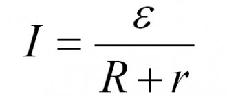
The basis for calculating the input and output voltage of a circuit is Ohm’s law, familiar from school physics courses. The basic formula for calculating the voltage on a section of a circuit looks like this:
The voltage in the AC circuit can be determined using the following formula:
U=I/Z, where
in this formula, Z stands for the resistance (ohms) that was obtained throughout the circuit.
In some cases, indicators cannot be calculated directly from these formulas.
- In cases where conductors or dielectrics are exposed to high voltage.
- In cases of rapidly changing electromagnetic fields during the passage of high frequency currents. In this case, it is also necessary to take into account the inertia of charge-carrying particles.
- Under conditions of superconductivity properties appearing if the circuits operate at extremely low temperatures.
- When a conductor is heated by current flowing through it.
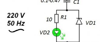
- For LEDs. The relationship between current and voltage drop in this case is nonlinear.
- For processes in semiconductor-based devices.
AC Voltage Undervoltage
An alternating voltage of 220 Volts is widely used for domestic needs; due to its physical characteristics, it is much easier to reduce it to any value or carry out any other manipulations. In most cases, electrical appliances are already designed to be powered from the electrical network, but if they were purchased abroad, then the voltage level for them may differ significantly.
For example, devices brought from the USA are powered by 110V AC, and some craftsmen undertake to rewind the step-down transformer to obtain the desired level. But it should be noted that the pulse converter, which is often included with various power tools and devices, should not be rewound, as this will lead to its incorrect operation in the future. It is much more advisable to install an autotransformer or another at the rating you need in order to lower the voltage.
Using a transformer
Changing the voltage value using electrical machines is used in power supplies and rechargers. But to reduce the source voltage in this way, you can use different types of converter transformers:
- With output from the middle point - they can produce a potential difference of both 220V and half as much - 127V or 110V. From it you can take the set nominal value for the same 110V from the middle point. These are factory products that were installed en masse in old Soviet televisions and other devices. But this converter circuit has a significant drawback - if the integrity of the winding below the middle terminal is disrupted, then the output of the transformer will receive a rating of a much higher value.
Rice. 3. Step-down using a transformer with a tap from the midpoint
- An autotransformer is a universal electrical machine that can not only lower the voltage, but also increase it to the level you need. To do this, simply move the knob to the desired position and monitor the readings obtained on the voltmeter.
Rice. 4. Using an autotransformer
- A step-down transformer that converts 220V to the rating you need or from any other voltage of variable frequency. This method can be implemented using both ready-made transformer models and homemade ones. Due to the availability of a large number of tools and devices, today anyone can assemble a transformer with the given parameters at home. You can learn more about this from the corresponding article: https://www.asutpp.ru/transformator-svoimi-rukami.html
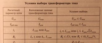
When choosing a specific model of electrical machine to reduce the voltage, pay attention to the characteristics of the specific model in relation to the devices that you want to power.
The most relevant parameters for transformers are:
- Power - the transformer must not only match the load connected to it, but also exceed it by at least 10 - 20%. Otherwise, the maximum current will lead to overheating of the transformer windings and further failure.
- Voltage rating – selected for both the primary and secondary circuits. Both parameters are equally important, since if you choose a model with an input voltage of 200 or 190V, you will get a proportionally larger value at the output when powered by 220V.
- Protection against electric shock - all windings and terminals from them must have sufficient insulation and protection from contact.
- Dust and moisture resistance class – determines the resistance of the equipment to environmental factors. In modern devices it is indicated by the IP index.
In addition, any voltage converter, even a pulse transformer, should be protected from short circuit currents and overloads in the windings. This will significantly reduce repair costs in the event of an emergency.
Using a resistor
To reduce the voltage, a voltage divider in the form of an active resistance is connected in series to the load circuit.
The main difficulty in adjusting the voltage on the connected device is the dependence on several parameters:
- voltage values;
- load resistance;
- source power.
If you step down from a household network, then it can be considered a source of infinite power and take this component as a constant. Then the resistor calculation will be performed using this method:
R = Uc/I - Rн,
Where
- R – resistor resistance;
- RН – resistance of the load device;
- I – current that must be provided in the nominal mode of the device;
- UC – network voltage.
After calculating the resistor value, you can select the appropriate model from the available range. It is worth noting that it is much more convenient to change the potential using a variable resistor connected to the circuit. By connecting it in series with the load, you can select the position in such a way as to reduce the voltage to the required value. However, this method cannot be called effective, since in addition to working in the device, electrical energy will simply be dissipated by a resistor, so this option is a temporary or one-time solution.
Determining the current strength across a resistor for different types of connection
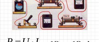
The easiest way to determine the current in a resistor is to use a multimeter. The measurement is carried out in the open circuit after the resistor. The maximum range of values is set on the tester, and the probes of the device are connected to the place where the conductor is disconnected. The multimeter display will show the results of measuring the current in the resistor. I = U/R, where we have I – current, U – voltage, R – resistance.
In the SI system, these quantities are measured in amperes (A), volts (V), ohms (Ohm), respectively.
By substituting the required values into the formula, you can determine the resistance, voltage and current on a resistor or any section or element of an electrical circuit.
How to lower the voltage from 12 to 5 volts using a microcircuit
Nothing fundamentally changes in this case either. If we compare this reduction option through a microcircuit with the option using a resistor. In fact, everything is the same here, except that useful “intelligent” features are added for adjusting the internal resistance of the microcircuit based on the current consumption. That is, as we understood from the paragraph above, depending on the consumption current, the calculated resistance should “float”. This is exactly what happens in a microcircuit when the resistance is adjusted to the load in such a way that the output of the microcircuit is always the same supply voltage! Well, plus there are such “useful buns” as protection against overheating and short circuit. As for microcircuits, so-called 5-volt voltage stabilizers, these could be: LM7805, KREN142EN5A. The connection is also very simple.
Of course, for the microcircuit to operate efficiently, we place it on a radiator. The stabilization current is limited to 1.5 -2 A. These are the principles of reducing the voltage from 12 to 5 volts. Now, once you understand them, you can easily calculate what resistance should be installed or how to select a microcircuit to obtain any other lower voltage. It remains to say a few words about PWM.
Wide pulse modulation is a very promising and, most importantly, highly efficient method of powering the load, but again with its pitfalls. The whole essence of PWM comes down to delivering in pulses a supply voltage that, together with moments of no voltage, will provide power and average voltage sufficient to operate the load. And here there can be problems if you connect the power source from one device to another. Well, the simplest problems are the lack of those characteristics that are stated. Possible interference and unstable operation. In the worst case, a PWM power supply can completely burn out a device for which it was not originally intended!
How to lower the voltage from 12 to 5 volts using a resistor
The simplest thing is to take and use an unstabilized circuit. That is, when we simply lower the voltage due to resistance and that’s it. There is nothing special to talk about this principle, we just calculate according to the formula above and that’s it. Let me give you an example. Let's say we reduce it from 12 volts to 5.
R=U/I. The tension is understandable, but look, we don’t have enough data! Nothing is known about the “consumption”, about the current consumption. That is, if you decide to calculate the resistance to reduce the voltage, then you definitely need to know how much our load “wants to eat”.
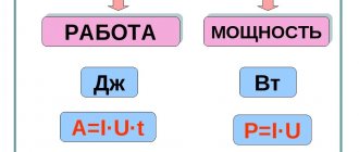
You will need to look at this value on the device that you are going to power or in the instructions for it. Let's assume that the current consumption is 50 mA = 0.05 A. It also remains to note that using this formula we will select a resistance that will completely suppress the voltage, but we need to leave 5 volts, then we substitute 12-5 = 7 volts into the formula. R= 7/0.05=140 Ohm you need resistance to get 5 from 12 volts, with a load current of 50 mA. It remains to mention something equally important! The fact that any energy suppression, and in this case voltage, is associated with power dissipation, that is, our resistor will have to “withstand” the heat that it will dissipate. The resistor power is calculated using the formula. P=U*I. We get it. P=7*0.05=0.35 W should be the power of the resistor. No less. Now the calculation course for a resistor can be considered complete.
Application
The use of such circuitry in practice is demonstrated by the following examples. To calculate electrical parameters without taking into account load resistance, the manual and automated methods discussed above are suitable.
READ MORE: Do-it-yourself concrete floor in the garage
Potentiometers
If the resistor is equipped with a slider and a corresponding drive, the resistance can be changed smoothly. This solution allows you to more accurately change the output voltage compared to discrete circuits. The main disadvantage is the complexity of the design, which, in addition to increasing the cost, reduces reliability. It is necessary to ensure the tightness of the working area to prevent contamination and prevent corrosion processes.
Potentiometer circuit diagram
Voltage divider circuit using resistors
The voltage divider circuit includes an input voltage source and two resistors. Below you can see several schematic versions of the divider, but they all have the same functionality.
Recommended reading: Stepper motor control
Let's denote the resistor that is closer to the plus of the input voltage (Uin) as R1, and the resistor that is closer to the minus as R2. The voltage drop (Uout) across resistor R2 is the reduced voltage resulting from the use of a resistor voltage divider.
Serial connection
This is the name for combining two or more resistors into one section of a circuit, in which their connection to each other occurs only at one point. Impedance when connected in series is defined as the sum of the resistances of each individual element: Rtotal = R1+R2+…+Rn.
Consequently, the current flowing through such a chain will become less and less after passing through a series-connected resistor. The more elements there are in the chain, the more difficult it will be for him to pass them all. Thus, its overall value is determined as Itotal = U / (R1+R2+…+Rn).
Therefore, it can be argued that in a series connection there is only one path for current to flow. The greater the number of resistors in the line, the less current will be in this section.
The drop in potential difference with this type of connection on each element will have its own meaning. It is determined by the formula URn = IRn*Rn, and the greater the impedance of the element, the more energy it will begin to release.