Resistor values are represented by so-called resistor rows (for example, row E24
). Resistor series are the result of standardization of resistor ratings. For constant resistors there are six so-called rows: E6, E12, E24, E48, E96 and E192, and for variable resistors there is one row - E6. In addition, there is an additional series E3. The number after the letter E indicates the number of nominal resistor values in each decimal interval.
The resistor values correspond to the numbers in the tables below or to the numbers obtained by multiplying or dividing these numbers by 10n (where n is a positive or negative integer). For example, according to the E6 series, the resistor values in each decade must correspond to the numbers 1; 1.5; 2.2; 3.3; 4.7; 6,8 or numbers obtained by multiplying or dividing these numbers by 10n, where n is a positive or negative integer. For example 10, 100, 15, 150 or 0.1, 0.01, 0.15, 0.015, etc. The principle of constructing the series E48, E96 and E192 is similar to that given with the only difference being that the number of intermediate values of denominations increases.
What is a series of denominations?
This concept establishes a certain pattern of alternating values for any radio components, including resistors. The existing standard was first approved back in 1948 and was designated by the Latin letter E, meaning EIA in the Electronic Industries Alliance. Following the letter E is a number indicating a specific line of values; it also shows the number of denominations available in this series. For example, E6 breaks down the nominal power, capacitance or resistance in the range from 0 to 10 into six units; if compared with E96, it will already have 96 of these units.
From a mathematical point of view, nominal values are a logarithmic function, so the step of change in nominal resistances can be determined by the formula:
where n is the serial number of a particular member, and N is the number of the series.
To select the desired model from the proposed data lines, the set value, for example, for E12 is 1... 1.2... 1.5... etc. and multiplied by a decimal factor - 10, 100, 1000, etc. until the desired value is reached. There are seven standard denominations in total, although the first of them is no longer produced today, but you can still find it in old devices. Next, we will consider the features of each of a number of part ratings.
How is it formed
Resistor power
The formation of rows of resistors is carried out strictly in accordance with the rules determined by the manufacturing technology of these radio components. Since any manufactured resistive component has some degree of error in its main parameter (resistance), and the values of these deviations can vary, simply using continuous series becomes irrelevant.
For example, for a part with a resistance of 100 Ohms specified by the manufacturer and a deviation of 10%, the real value may be 104 Ohms, then it becomes pointless to manufacture a separate component with this rating. The next element in such a line can be used with a 120 Ohm resistor; at the lower limit of the permissible interval there will be an indicator of 108 Ohms, and at the upper limit - 132. The next element can be a resistor of approximately 150 Ohms. There is a need for a system that takes into account both the denomination and the range of its possible changes.
Using a similar principle, a list of radio components with a selected error can be generated. If it is 10%, the list is supposed to consist of 12 units. If the goal is to achieve a more accurate categorization (for example, an error of 5%), the elements will be more tightly packed, without a large gap in values between neighboring ones, and their number will be twice as large. From these values, tabular summaries can be generated. Tables for different series will differ in the number of symbols involved and the spacing of nominal values.
Resistor series E12
Series E3
The nominal series E3 includes only three resistance values: 1; 2.2; 4.7. In addition, the electrical resistance of the resistors may deviate from the declared parameter. The same can be repeated by the capacitance of the capacitor and other characteristics of parts of electronic circuits that comply with E3 standards. Normal fluctuations in the main characteristics are considered to be no more than 50%, which means that if you want to purchase a 10-ohm non-wire resistor, the factory can produce it in the range from 5.1 to 14.9 ohms, without going beyond the boundaries set by the standard.
SMD resistors
Due to their small size, SMD resistors are individually marked. These can be either numbers or numbers with letters. Designations are found in three variations:
- Three digits - the first two digits will show the resistance value, and the last one will show the multiplier.
- Four digits - the initial three of them indicate the resistance of the resistor, and the fourth will tell you about the multiplier.
- Two numbers and a symbol - the resistance indicator is hidden in the first two numbers, but to decipher them you will need to use a table. The symbol denotes the multiplier.
It is also necessary to take into account the letter that indicates the multiplier: S=10¯²; R=10¯¹; B=10; C=10²; D=10³; E=10⁴.
As for amateurs and beginners, it is much easier for them to determine the value of parts using tables that can be printed and always kept at hand, or online calculators that help accurately determine the parameters of the part.
Row E6
Here, to indicate denominations, there are six possible values: 1; 1.5; 2.2; 3.3; 4.7; 6.8. When indicating the nominal capacitances, resistances and other characteristics of radio components, E6 has the following differences:
- the error tolerance is no more than 20%, which gives a considerable deviation, which must be taken into account when operating precision instruments;
- when using color markings for ceramic or carbon resistors, the parts will have a black stripe, characterizing their possible error;
Determination of permissible deviation by color marking
- They are most widespread in power equipment, where the main role of the resistor is to dampen the current load, and the existing error will not have a significant effect.
Design and properties
The conductive material is applied to a dielectric frame with terminals for connecting to the circuit. Based on the use of materials in manufacturing, the basic types of resistors are divided into:
- Wired, using metal wires with carefully selected conductivity;
- Non-wire, which are divided into thin-film, using metal oxides and metal dielectrics, carbon and boron-carbon compounds; thick film, with resist based on conductive plastics and lacquer films, cermit compounds; volumetric, with organic or inorganic dielectric.
- Metal foil.
Structurally, products for surface-mounted and printed circuit mounting differ from miniature integrated parts of modules and microcircuits. Extreme operating conditions and use of electronic equipment require vacuum, non-insulated, insulated or sealed elements of process modules and instruments. Some types of equipment require the use of high-frequency, high-voltage or precision components.
Series E12
In comparison with the previous one, it will no longer have six, but twelve options for ratings for electronic components from 1 to 8.2. The value of the nominal data increases proportionally.
According to their characteristics, the E12 series differ in the following data:
- the permissible error of inductors or resistors is no more than 10%;
- if the resistor has a color marking, then the strip indicating a possible deviation from the declared resistance should be gray or silver;
- Their scope of application covers the field of trimmers and variable resistors, and is also used for some household appliances.
Marking
Alphanumeric code
Elements with wire leads are identified by writing on the surface of the housing. The numbers indicate the denomination, and the letters indicate the measurement range. The letters "E" and "R" are for ohms, "K" is for kilohms, and "M" is for megohms.
The letter in the marking acts as a decimal point. For example, the designation 5R8 corresponds to a resistance of 5.8 Ohms, 7K8 means 7.8 kOhms, and M59 equals 590 kOhms.
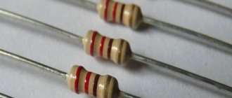
Color coding
For small components whose labels cannot be read, color marking of resistors using colored stripes has been developed.
A number of colored stripes are shifted to the edge of the case, and the countdown begins from the stripe closest to the edge.
If the marking contains five bars, then the first three will show the resistance value in ohms, the next one determines the multiplier, and the last one indicates the tolerance.
Coding of SMD elements
The photo of surface-mount resistors shows that small sizes require the use of other designation methods. Manufacturers have introduced three basic methods of coding, combining products into groups by size.
Products with a tolerance of 2, 5 and 10%. There is a digital mark on the case, for example 330, 683, 474. The first two numbers indicate the mantissa, and the third acts as an indicator of the power of the number 10. Accordingly, the inscription 330 shows 33*1=33 Ohm, 683 means 68*1000=68 kOhm, 473 respectively 47* 10000=470 kOhm. Some models use the letter "R" as a decimal point.
Models of size 0805 and others with a one-percent tolerance are designated according to a principle similar to the first group: the first three digits are the mantissa, the fourth, the multiplier is a power of the base 10, it is also allowed to use the letter “R”. Set 7430 corresponds to a value of 743 ohms
SMD size 0603 are marked with a combination of two numbers and a letter, which determines the degree of the multiplier: A - zero degree, B - first, C - second, D - third, E - fourth, F - fifth, R - minus the first, S - minus the second , Z – minus the third power. The number indicates the code by which the mantissa is found in the EIA-96 table.
For example, code 75C. 75 in the table corresponds to 590. The letter “C” indicates a multiplier of 100. Accordingly, 590*100=59 kOhm.
Series E24
This type of marking has twice the number of denominations compared to the previous one.
Distinctive features of the E24 series are:
- Deviation from the value set by the manufacturer is allowed no more than 5%; a larger value is unacceptable due to overlap of the adjacent value
- the colored stripes for such nominal rows are golden in color;
- most common among radio amateurs, since the wire leads are easy to solder and use for assembling electrical circuits, and the percentage of error does not greatly affect the electrical parameters.
Resistor.
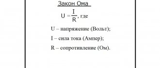
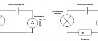
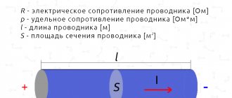
So let's start with the basic definition of a resistor. A resistor is, first of all, a passive element of an electrical circuit that has a certain resistance value (it can be constant or variable). This element is designed to linearly convert current into voltage and vice versa. After all, as we remember from Ohm’s law, voltage and current are related to each other precisely through the amount of resistance:
I = \frac{U}{R}
Resistors are among the most widely used components. It is rare to find a circuit in which there is not a single resistor. The main parameter of a resistor, as is already clear from the definition, is its electrical resistance, measured in Ohms (Ohms).
Series E48
The number of options for resistance to electric current is still twice as large as E24; starting from it, the values are separated not only by tenths, but also by hundredths. A distinctive feature of this and subsequent series is their high accuracy, namely, E48 can deviate from the declared data by only 2%.
To indicate the E48 series of colored stripes, red is applied; in the operation of household appliances, such a deviation is completely invisible, since ordinary voltage fluctuations in the electrical circuit have a much more significant effect. Therefore, their use in modeling is highly specific and belongs to precise elements.
Fixed resistance resistors (fixed resistors).
unchanged during operation.
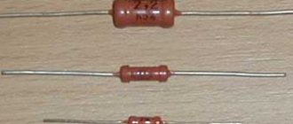
. Structurally, such a resistor is a ceramic tube, on the surface of which a conductive layer is applied, which has a certain ohmic resistance. Metal caps are pressed along the edges of the tube, to which resistor leads made of tinned copper wire are welded. The top of the resistor housing is covered with moisture-resistant colored enamel.
The ceramic tube is called a resistive element
and depending on the type of conductive layer applied to the surface, resistors are divided into
non-wire
and
wire
.
2.1. Non-wire resistors.
Non-wire resistors are used to operate in electrical circuits of direct and alternating current, in which relatively small load currents flow. The resistive element of the resistor is made in the form of a thin semiconducting film
, applied to a ceramic base.
The semiconducting film is called resistive layer
and is made from a film of a homogeneous substance with a thickness of 0.1 - 10 microns (micrometer) or from
microcompositions
. Microcompositions can be made of carbon, metals and their alloys, oxides and compounds of metals, and also in the form of a thicker film (50 microns) consisting of a crushed mixture of a conductive substance.
Depending on the composition of the resistive layer, resistors are divided into carbon, metal-film (metallized), metal-dielectric, metal-oxide and semiconductor. The most widely used are metal film and carbon composite fixed resistors. Domestic resistors include MLT, OMLT (metalized, enamel-lacquered, heat-resistant), BC (carbon) and KIM, TVO (composite).
Non-wire resistors are characterized by their small size and weight, low cost, and the ability to be used at high frequencies up to 10 GHz. However, they are not stable enough, since their resistance depends on temperature, humidity, applied load, operating time, etc. But still, the positive properties of non-wire resistors are so significant that they are the ones that are most widely used.
2.2. Wirewound resistors.
Wirewound resistors are used in DC electrical circuits. When making a resistor, a thin wire made of nickel, nichrome, constantan or other alloys with high electrical resistivity is wound onto its body in one or two layers. The high resistivity of the wire allows the resistor to be made with minimal consumption of materials and small dimensions. The diameter of the wires used is determined by the current density passing through the resistor, technological parameters, reliability and cost, and starts from 0.03 - 0.05 mm.
To protect against mechanical or climatic influences and to secure the turns, the resistor is coated with varnishes and enamels or sealed. The type of insulation affects the heat resistance, dielectric strength and outer diameter of the wire: the larger the diameter of the wire, the thicker the insulation layer and the higher the dielectric strength.
The most widely used wires are enamel insulation PE (enamel), PEV (high-strength enamel), PETV (heat-resistant enamel), PETK (heat-resistant enamel), the advantage of which is its small thickness with a fairly high electrical strength. Common high-power resistors are enameled wire resistors such as PEV, PEVT, S5-35, etc.
Compared to non-wire resistors, wire resistors are more stable. They can operate at higher temperatures and withstand significant overloads. However, they are more difficult to manufacture, more expensive and unsuitable for use at frequencies above 1-2 MHz, since they have high intrinsic capacitance and inductance, which manifest themselves already at frequencies of several kilohertz.
Therefore, they are mainly used in DC or low-frequency circuits, where high accuracy and stability of operation are required, as well as the ability to withstand significant overload currents that cause significant overheating of the resistor.
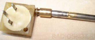
With the advent of microcontrollers, modern technology has become more functional and at the same time much smaller. The use of microcontrollers has made it possible to simplify electronic circuits and thereby reduce the current consumption of devices, which has made it possible to miniaturize the element base. The figure below shows SMD resistors that are soldered to the board from the printed circuit board side.
Series E96
It has a twice wider range of denominations than E48. Compared to others, the E96 series has the following distinctive features:
- the error of an element manufactured according to the standard of this rating may differ by no more than 1% from the nameplate value, for example, a 100 Ohm resistor will not go beyond 99 or 101 Ohms;
- the color indication of accuracy on the body of the radio component will have a brown stripe;
- in practice it is used in the assembly of printed circuit boards, installed in control circuits, relay protection, telemechanics, etc.
A significant disadvantage is the relatively higher cost compared to less precise resistors.
Series E192
Is the largest number of denominations, the series includes 192 units of possible options and provides the widest range for selection. Differs in the following data:
- the resistance error cannot exceed 0.5%, 0.25 and even 0.1%, which puts them in the category of ultra-precise equipment; SMD resistors are often developed on their basis;
- from the point of view of the color designation of the row, a green, blue or purple stripe is depicted on the body of the device;
- used in ultra-precise measuring systems and electronic computers.
A significant disadvantage is the highest cost in comparison with others. To make it easier to understand the difference between the nominal series of the last three orders, below is a table with resistor resistance values.
Table: ratings of rows E48, E96, E192
Table: ratings of rows E48, E96, E192
Resistor markings
A simple calculator for calculating resistor values by color. By clicking on the colors in the table, we color the resistor with stripes.
- As a result, we get the value and tolerance of the resistor we need.
- The first stripe from which the count is taken is usually wider or located closer to the resistor terminal.
First of all, you should pay attention to the relatively new and not everyone is familiar with the EIA-96 marking standard, which consists of three characters - two numbers and a letter. The compactness of writing is compensated by the inconvenience of deciphering the code using a table
Three-character marking EIA96
EIA-96 planar element coding (SMD)
provides for determining the value of three marking symbols for precision (high-precision) resistors with a tolerance of 1%.
The first two digits are the denomination code from 01
before96
corresponds to a denomination number from
100
to
976
according to the table. The third character - a letter - is the multiplier code.
Each of the letters X
,Y
,
Z
,
A
,
B
,
C
,
D
,
E
,
F
,
H
,
R
,
S
corresponds to the multiplier according to the table. The resistor value is determined by the product of the number and the multiplier.
The principle of decoding SMD resistor codes of E24
and E48
much simpler, does not require tables and is described separately below.
EIA-96 resistors
,E24
,
E48
.
Resistance 0 ohm ±1%, EIA-96
as a result of calculation means incorrect input.
| CodeNumberCodeNumberCodeNumberNumberNumber 01 | 100 | 25 | 178 | 49 | 316 | 73 | 562 |
| 02 | 102 | 26 | 182 | 50 | 324 | 74 | 576 |
| 03 | 105 | 27 | 187 | 51 | 332 | 75 | 590 |
| 04 | 107 | 28 | 191 | 52 | 340 | 76 | 604 |
| 05 | 110 | 29 | 196 | 53 | 348 | 77 | 619 |
| 06 | 113 | 30 | 200 | 54 | 357 | 78 | 634 |
| 07 | 115 | 31 | 205 | 55 | 365 | 79 | 649 |
| 08 | 118 | 32 | 210 | 56 | 374 | 80 | 665 |
| 09 | 121 | 33 | 215 | 57 | 383 | 81 | 681 |
| 10 | 124 | 34 | 221 | 58 | 392 | 82 | 698 |
| 11 | 127 | 35 | 226 | 59 | 402 | 83 | 715 |
| 12 | 130 | 36 | 232 | 60 | 412 | 84 | 732 |
| 13 | 133 | 37 | 237 | 61 | 422 | 85 | 750 |
| 14 | 137 | 38 | 243 | 62 | 432 | 86 | 768 |
| 15 | 140 | 39 | 249 | 63 | 442 | 87 | 787 |
| 16 | 143 | 40 | 255 | 64 | 453 | 88 | 806 |
| 17 | 147 | 41 | 261 | 65 | 464 | 89 | 825 |
| 18 | 150 | 42 | 267 | 66 | 475 | 90 | 845 |
| 19 | 154 | 43 | 274 | 67 | 487 | 91 | 866 |
| 20 | 158 | 44 | 280 | 68 | 499 | 92 | 887 |
| 21 | 162 | 45 | 287 | 69 | 511 | 93 | 909 |
| 22 | 165 | 46 | 294 | 70 | 523 | 94 | 931 |
| 23 | 169 | 47 | 301 | 71 | 536 | 95 | 953 |
| 24 | 174 | 48 | 309 | 72 | 549 | 96 | 976 |
CodeZ Multiplier
| 0.001 | |
| Y or R | 0.01 |
| X or S | 0.1 |
| A | 1 |
| B or H | 10 |
| C | 100 |
| D | 1000 |
| E | 10000 |
| F | 100000 |
Three-digit marking. The first two digits are the denomination number. The third digit is the decimal logarithm of the multiplier. 0=lg1, multiplier 1.1=lg10, multiplier 10.2=lg100, multiplier 100.3=lg1000, multiplier 1000. Etc., according to the number of zeros of the multiplier. The product of the number and the multiplier will determine the resistor value. For this article, use the calculator window above as for EIA-96.