Any lover of homemade products and electronics use diodes as indicators, or as lighting effects and lighting. In order for the LED device to glow, you need to connect it correctly. You already know that a diode only conducts current in one direction. Therefore, before soldering, you need to determine where the anode and cathode of the LED are.
You may see two LED designations on a circuit diagram.
The triangular half of the designation is the anode, and the vertical line is the cathode. The two arrows indicate that the diode is emitting light. So, the diagram indicates the anode and cathode of the diode, how to find it on a real element?
Pinout of 5mm diodes
To connect the diodes as in the diagram, you need to determine where the plus and minus of the LED are. First, let's look at the example of common low-power 5 mm diodes.
The figure above shows: A - anode, K - cathode and schematic symbol.
Pay attention to the flask. You can see two parts in it - this is a small metal anode, and a wide part that looks like a bowl is the cathode. The plus is connected to the anode, and the minus to the cathode.
If you are using new LED elements, it is even easier for you to determine their pinout. The length of the legs will help determine the polarity of the LED. Manufacturers make short and long legs. The plus is always longer than the minus!
If you are not soldering a new diode, then its plus and minus are the same length. In this case, a tester or a simple multimeter will help to determine the plus and minus.
Features of operation
Diodes, when voltage is applied to them, tend to conduct current in only one direction. When it is turned back on, no direct current will flow.
In order not to make a mistake, when soldering a two-terminal circuit into a circuit, you need to find out where the diode is plus and where the minus is. This is easy to do if there are appropriate markings on the device. Often there are no obvious signs of pole markings on the housing. In such cases, the determination of the cathode and anode is carried out in other ways.
How to determine the anode and cathode of diodes 1W or more
In flashlights and spotlights, 5mm samples are used less and less; they have been replaced by powerful elements with a power of 1 watt or more or SMD. To understand where the plus and minus are on a powerful LED, you need to carefully look at the element from all sides.
The most common models in such a case have a power of 0.5 watts. The polarity mark is circled in red in the figure. In this case, the anode of the 1W LED is marked with a plus sign.
Polar and non-polar capacitors - what is the difference
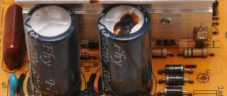
All kinds of capacitors, used today almost everywhere in electronics and electrical engineering, contain various substances as dielectrics
However, with regard specifically to electrolytic capacitors, in particular also tantalum and polymer ones, when they are included in the circuit, it is important to strictly observe polarity. If such a capacitor is connected incorrectly to the circuit, it will not be able to work normally.
These capacitors are therefore called polar capacitors. What is the fundamental difference between a polar capacitor and a non-polar one? Why is it that some capacitors do not care how they are included in the circuit, while for others it is fundamentally important to maintain polarity?
It will be interesting Formula for calculating capacitor resistance
Let's try to figure this out now. The point here is that the manufacturing process for electrolytic capacitors is very different from, say, ceramic or polypropylene. If for the latter two both the plates and the dielectric are homogeneous in relation to each other, that is, there is no difference in the structure at the plate-dielectric interface on both sides of the dielectric, then electrolytic capacitors (cylindrical aluminum, tantalum, polymer) have a difference in the structure of the dielectric transition -plating on both sides of the dielectric: the anode and cathode differ in chemical composition and physical properties.
When an electrolytic aluminum capacitor is made, they do not simply roll up two identical foil plates lined with electrolyte-impregnated paper. On the side of the anode plate (to which + is applied) there is a layer of aluminum oxide applied to the etched surface of the foil in a special way. The anode is designed to give electrons through an external circuit to the cathode during the charging of the capacitor. The negative plate (cathode) is simply aluminum foil; during the charging process, electrons come to it through an external circuit. The electrolyte here serves as a conductor of ions.
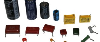
Polar and non-polar capacitors.
The same is the case with tantalum capacitors, where tantalum powder serves as the anode, on which a film of tantalum pentoxide is formed (the anode is connected to the oxide!), which functions as a dielectric, then there is a layer of semiconductor - manganese dioxide as an electrolyte, then a silver cathode, from which electrons will leave during the discharge process.
Polymer electrolytic capacitors use a lightweight conductive polymer as the cathode, but otherwise the processes are similar. The essence is oxidation and reduction reactions, like in a battery. The anode is oxidized during the electrochemical discharge reaction, and the cathode is reduced.
When an electrolytic capacitor is charged, there is an excess of electrons at its cathode, on the negative plate, imparting a negative charge to this terminal, and at the anode, a lack of electrons, giving a positive charge, thus obtaining a potential difference. If a charged electrolytic capacitor is connected to an external circuit, then excess electrons will run from the negatively charged cathode to the positively charged anode, and the charge will be neutralized. In the electrolyte, positive ions move at this moment from the cathode to the anode.
If such a polar capacitor is connected incorrectly to the circuit, then the described reactions will not be able to proceed normally, and the capacitor will not work normally. Non-polar capacitors can operate in any connection, since they have neither an anode, nor a cathode, nor an electrolyte, and their plates interact with the dielectric in the same way as with the source.
Capacitor polarity.
But what if you only have polar electrolytic capacitors at hand, but you need to connect the capacitor to a current circuit with changing polarity? There is one trick for this. You need to take two identical polar electrolytic capacitors and connect them together in series with terminals of the same name. You will get one non-polar capacitor from two polar ones, the capacitance of which will be 2 times less than each of its two components.
It will be interesting How much do ceramic capacitors cost?
On this basis, by the way, non-polar electrolytic capacitors are made, in which an oxide layer is present on both plates. For this reason, non-polar electrolytic capacitors are significantly larger than polar capacitors of similar capacity. Based on this principle, electrolytic starting non-polar capacitors are also manufactured, designed to operate in alternating current circuits with a frequency of 50-60 Hz.
Polar and non-polar capacitor
How to find out the polarity of SMD?
SMDs are actively used in practically any technology:
- Light bulbs;
- LED strips;
- flashlights;
- indication of something.
You won’t be able to see their insides, so you need to either use testing devices or rely on the LED housing.
For example, on the SMD 5050 case there is a mark on the corner in the form of a cut. All pins located on the tag side are cathodes. Its body contains three crystals, this is necessary to achieve high brightness.
A similar designation for SMD 3528 also indicates the cathode, take a look at this photo of the LED strip.
The marking of the SMD 5630 pins is similar - the cut indicates the cathode. It can also be recognized by the fact that the heat sink on the bottom of the case is shifted towards the anode.
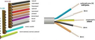
Speaker cable parameters
An audio wire has three basic properties: capacitance, inductance and resistance. Due to the conditions in which speaker wire operates, its most important quality is resistance. This is the main parameter that distinguishes an acoustic cable from a regular one. This is due to the rather low frequencies and absolute impedance of the system. Most audio installations have an impedance of 4 to 15 ohms.
Speaker cable structure
Increasing the resistance can affect the efficiency of the system because the speaker reduces the drive current. The next problem is that the back EMF generated by the speaker must have a low impedance source. As the source impedance increases, the back EMF is absorbed to a lesser extent. This affects the performance of the speaker, especially in the area of low harmonics, then they will not be as pronounced and will sound less natural.
You may be interested in this Features of cable lugs
Basically, the negative effects of speaker wire become noticeable when the cable resistance reaches about 5% of the total speaker resistance. Since it is proportional to its length, the resistance of the AC can be adjusted by modifying the following parameter:
The length should be as short as possible, then the resistance will decrease.
Another prescriptive rule that must be followed when assembling an audio system is that the size of the line to both speakers must be kept the same, and therefore they will have equal impedance. The system will be effectively balanced.
Note! The thicker the wire, the lower the resistance; this is the difference between high-quality and low-quality products. It is the relationship between speaker impedance, length and length that affect the impedance
It should ensure that the speaker cable impedance is less than 5% of the speaker's rated impedance under different loads.
Determine polarity with a multimeter
When replacing diodes with new ones, you can determine the plus and minus of your device's power supply from the board.
LEDs in spotlights and lamps are usually soldered onto an aluminum plate, on top of which a dielectric and current-carrying tracks are applied. It usually has a white coating on top; it often contains information about the characteristics of the power source, and sometimes the pinout.
But how can you find out the polarity of an LED in a light bulb or matrix if there is no information on the board?
For example, on this board the poles of each LED are indicated and their name is 5630.
To check for serviceability and determine the plus and minus of the LED, use a multimeter. We connect the black probe to minus, com or a socket with a grounding sign. The designation may differ depending on the multimeter model.
Next, select the Ohmmeter mode or the diode test mode. Then we connect the multimeter probes one by one to the diode terminals, first in one order, and then vice versa. When at least some values appear on the screen, or the diode lights up, it means the polarity is correct. In diode testing mode, the values are 500-1200 mV.
In measurement mode, the values will be similar to those in the figure. A unit in the leftmost digit indicates exceeding the limit, or infinity.
Using technical documentation
Other ways to determine pins can be found in the technical documentation for the elements - in reference books or online sources. To do this, at a minimum, you need to know the type of LED or its manufacturer. The documentation may contain information about the dimensions and pinout of the device.
But even if this information is not found in the specification, the efforts will not be in vain. Technical documentation can become a source of information about the limiting parameters of an electronic device. This knowledge will help you choose the right operating mode, as well as prevent the LED from failing when checking the pin locations.
Other ways to determine polarity
The easiest option for determining where the LED is plus is batteries from the motherboard, size CR2032.
Its voltage is about 3 volts, which is quite enough to light the diode. Connect the LED, depending on its glow you will determine the location of its pins. This way you can test any diode. However, this is not very convenient.
You can assemble a simple probe for LEDs, and not only determine their polarity, but also the operating voltage.
Homemade probe circuit
When the LED is connected correctly, a current of about 5-6 milliamps will flow through it, which is safe for any LED. The voltmeter will show the voltage drop across the LED at this current. If the polarity of the LED and the probe match, it will light up and you will determine the pinout.
You need to know the operating voltage, since it differs depending on the type of LED and its color (red takes less than 2 volts).
And the last method is shown in the photo below.
Turn on the Hfe mode on the tester, insert the LED into the connector for testing transistors, into the area marked as PNP, into holes E and C, with the long leg in E. This way you can check the functionality of the LED and its pinout.
If the LED is made in a different form, for example, smd 5050, you can use this method simply - insert regular sewing needles into E and C, and touch them with the LED contacts.
Any lover of electronics, and even homemade products in general, needs to know how to determine the polarity of an LED and how to check them.
Be careful when choosing the elements of your circuit. At best, they will simply fail faster, and at worst, they will instantly burst into blue flame.
Please rate the article. We tried our best:)
Did you like the article? Tell us about her! You will help us a lot :)
Using a battery
If there is no power source, you can try to determine the location of the leads from the galvanic cell, but you should keep in mind the features of such a test:
- The battery may produce a voltage that is insufficient to open the pn junction.
- household galvanic cells have low power, and the output load current is small - it depends on the initial power of the battery and on the residual charge.
The table shows the parameters of some domestic LEDs. Obviously, common one-and-a-half-volt chemical current sources will not be able to ignite any device on the list.
| Device type | Forward voltage drop, V | Operating current, mA |
| AL102A | 2,8 | 5 |
| AL307A | 2 | 10 |
| AL307V | 2,8 | 20 |
To increase the voltage, you can connect the batteries in series. To increase power - in parallel (only for elements of the same voltage!). The result may be a cumbersome design that does not guarantee the final result. Therefore, it is better to use this method in cases where there are no other ways.
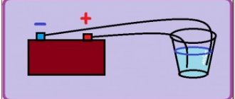
The process of electrolysis or battery charging
These processes are similar and inverse to a galvanic cell, since here the energy is not supplied through a chemical reaction, but on the contrary, the chemical reaction occurs due to an external source of electricity.
In this case, the plus of the power source is still called the cathode, and the minus the anode. But the contacts of the charged galvanic cell or the electrodes of the electrolyzer will already have opposite names, let's figure out why!
Important! When a galvanic cell is discharged, the anode is minus, the cathode is plus, and when charging it is the other way around. Since the current from the positive terminal of the power source flows to the positive terminal of the battery, the latter can no longer be the cathode
Referring to the above, we can conclude that in this case, the battery electrodes conditionally change places when charging
Since the current from the positive terminal of the power source flows to the positive terminal of the battery, the latter can no longer be the cathode. Referring to the above, we can conclude that in this case, the battery electrodes conditionally change places when charging.
Then, through the electrode of the charged galvanic cell, into which electric current flows, it is called the anode. It turns out that when charging the battery, the plus becomes the anode, and the minus becomes the cathode.
LED device.
An LED diode consists of a semiconductor crystal, which is mounted on a substrate, a housing with contacts, and an optical system.
The devices of indicator (DIP), flat (SMD) and SOV elements differ externally.
DIP design device.
Sectional view of a DIP LED.
Contacts are mounted at the base of the device. A crystal (one or more) is fixed to the cathode. A wire is attached to the crystal. It connects the semiconductors to the anode. This is necessary for grouping two conductors with different types of conductivity. The LED element is hermetically covered with a lens on top. The device body is made in the form of an epoxy resin cylinder, the edge of which is cut off from the cathode side. The LED element is mounted by soldering long leads.
SMD design device.
Sectional view of an SMD LED.
The body is made of a parallelepiped. Its basis is a heat sink from the crystal. A semiconductor element is mounted on it. A contact wire connects it to the anode. The contacts are made flat. The element is hermetically covered with a lens on top.
Structural device of SOV.
COB technology is the latest direction in production.
Such light-emitting diodes have a thermally conductive substrate (usually aluminum) at the base. Semiconductor crystals, which are connected in a series-parallel circuit, are attached to it with non-conductive glue. Everything is covered with phosphor on top.
This type of LED is easy to install, produces a good luminous flux and does not distort colors. They are in demand in the production of small, bright spotlights and decorative lighting. Unlike DIP and SMD, they are capable of operating at elevated temperatures. But due to their design, they have a shorter service life in comparison.
If many crystals are mounted on one substrate, then such an LED element is called an LED matrix.
PCB Star design device.
It consists of one large crystal, which is mounted on an aluminum substrate in the shape of a star. Due to the increased crystal area, the LED power increases. Makes it easier to focus. Therefore, PCB Star is in demand in the production of bright light sources: from flashlights to floodlights.
We connect LED lamps with our own hands
Another important factor is that the use of such lamps preserves the environment due to the reduction of combustion products released into the air by power plants. Users of LED lamps agree that such lamps are characterized by compact sizes, economical use of electricity, the absence of difficulties in self-installation, and neither humans nor nature receive harmful radiation from them. It is likely that they will soon replace not only conventional incandescent lamps, but also energy-saving ones.
With all the many advantages, LED lamps have a noticeable disadvantage - a fairly high cost - about 20 - 50 USD. You can, of course, take the Chinese version, but it will work much less, and it will shine about the same as fluorescent lamps.
What is inside?
If we take a closer look at the lamp, from the inside, so to speak, we will see that the body contains a reflector and a set of small LEDs. Due to the high heating of LEDs, each has a special cooling radiator. And where they touch, thermal paste is applied for better contact and heat removal.
Depending on how many LEDs are in the lamp and what their power is, you can determine the total power of the entire lamp. There can be a different number of LEDs - either one or several dozen. All of them are components of the same electrical network and are controlled by a power supply according to a special connection diagram.
Using a power source
A more efficient way to determine polarity is to connect the LED to a power source.
Attention! You need to choose a source whose voltage does not exceed the permissible voltage of the LED. You can build a homemade tester using a regular battery and resistor. This requirement is due to the fact that if the connection is reversed, the LED may burn out or degrade its light characteristics.
Some say that they connected the LED this way and that, and it did not deteriorate. But the whole point is in the limiting value of the reverse voltage. In addition, the light bulb may not go out immediately, but its operating life will be reduced, and then your LED will not work for 30-50 thousand hours, as indicated in its characteristics, but several times less.
If the power of the battery for the LED is not enough, and the device does not light up no matter how you connect it, then you can connect several elements into a battery. We remind you that one hundred elements are connected in series plus to minus, and minus to plus.
Connecting flashing and multi-color LEDs
Externally, flashing LEDs are no different from conventional analogues and can flash in one, two or three colors according to the algorithm specified by the manufacturer. The internal difference is the presence of another substrate under the housing, on which the integrated pulse generator is located. The rated operating current, as a rule, does not exceed 20 mA, and the voltage drop can vary from 3 to 14 V. Therefore, before connecting a flashing LED, you need to familiarize yourself with its characteristics. If they are not there, then you can find out the parameters experimentally by connecting to an adjustable power supply at 5–15 V through a resistor with a resistance of 51–100 Ohms.
The multicolor RGB LED housing contains 3 independent crystals of green, red and blue. Therefore, when calculating resistor values, you need to remember that each glow color has its own voltage drop.