The marking contains information about the LED, and each manufacturer includes its own data in it. On LEDs, as a rule, there is not enough space to place markings, so you should look for them on packaging containers: boxes, bags. Some manufacturers place LEDs on a strip and wind them onto a reel. In this form they go on sale. The markings should be found on this reel. Do not hesitate to ask the seller for packaging containers in the store in order to find out the LED labeling.
LED labeling does not have a global standard; it varies from manufacturer to manufacturer. Everyone creates their own, in which they encrypt, in their opinion, the necessary data. To sort out the meanings of the markings of all manufacturers, you will need to write a whole reference book, so we will analyze only the markings of the most famous manufacturers (brands).
Philips marking
Let’s look at the marking of this company using the example of the well-known LED – Luxeon Rebel. Its marking: LXML-ABCD-EFGH
- LXML – series;
- A – type of light distribution (P for Lambertian distribution);
- B – emitted color (W – white, from the word White);
- C – white color (C – cold, N – neutral, W – warm);
- D – rated current (I for current 350 mA);
- E – digit reserved for future versions of LED;
- FGH – luminous flux measured in lumens.
For example, a white LED with a rated current of 350 mA will be labeled: LXML-PWxI-0xxx.
LED Luxeon of similar series have similar markings. In general terms, we can say that the marking of this diode is very informative in comparison with other manufacturers.
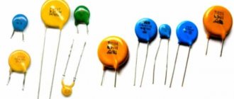
SMD diodes
In the SMD version, the diode body is sometimes so small that there are no markings at all. The characteristics of the devices depend little on the dimensions. The latter greatly influence the dissipated power. A larger current flows through the circuit; a diode must be larger in size to remove the resulting heat (Joule-Lenz law). As written, the marking of an SMD diode can be:
- Full.
- Abbreviated.
- Lack of markings.
SMD elements in the total volume of electronics occupy approximately 80% of the volume. Surface mounting. The invented method of electrical connection is as convenient as possible for automated assembly lines. The SMD diode marking may not match the contents of the case. With a large volume of production, manufacturers begin to cheat, putting inside something that is not at all what is marked with the symbol. A large number of inconsistent standards causes confusion in the use of microcircuit pins (for diodes - microassemblies).
Frame
The marking may include 4 digits indicating the housing size. They do not directly correspond to the dimensions, take a closer look at the question in GOST R1-12-0.062, GOST R1-12-0.125. For hobbyists who cannot afford to obtain regulations, it is easier to use reference tables. Let's keep in mind the fact: SMD cases can differ in small things from company to company, because each manufacturer tailors the element base to its own products. Samsung has one distance from the motherboard of the washing machine, LG has another. The dimensions of SMD housings will require different conditions, heat dissipation conditions, and other requirements will be met.
Cree markings
]Cree[/anchor] specializes in the production of high-power LEDs and is marked: SSSCCC-BD-0000-NNNNN
- the first three characters (SSS) are the series, for example XPG for the XP-G series;
- the second three characters (CCC) are the color, encoded using the abbreviations of the corresponding colors in English: WHT - white;
- ROY – royal (bright) blue;
- RED – red;
- AMB – orange;
- GRN – green;
- BLU – blue;
- HEW – high efficiency white;
- BWT – second generation white (we are talking about the second generation of white LEDs, for example, if the XP-G series was designated XPGWHT..., then the XP-G2 series will be designated XPGBWT...);
- 01 – white for outdoor lighting;
For example, let's take the Cree XP-E2 series light-emitting diode labeled XPEBWT-H1-0000-00AE7. Using the description, we can say that the marking reads as follows: led XP-E2 has a color rendering index of 80, color temperature of 4300K, luminous flux = 87.4 lm at a current of 350 mA.
To consolidate the material, we recommend watching a thematic video in which the author talks about the marking of light-emitting diodes CREE XM-L T6, XM-L2 U2 or XP-E Q5
Type of bulb and base
The LED lamps offered to customers differ in the shape and size of the bulb. These parameters are determined by specific values on the box.
Figure 2. Types of flasks
The most popular flask markings and their interpretation:
- A – traditional shape, reminiscent of a pear (similar to incandescent lamps);
- C – candle shape;
- R – resembles a mushroom;
- G – spherical flask;
- T – tubular design;
- P – spherical shape.
A socket is used to connect the device to the lighting system. The most popular are traditional sockets marked “E”. They provide a connection to the cartridge using a thread.
Figure 3. Lighting sockets
Next to the letter there is a number that determines the diameter of the thread. Many devices have a base abbreviated E27. They are suitable for replacing traditional incandescent lamps. Slightly less common are models with the abbreviation E14, which implies a reduced thread diameter.
In street lamps you can often find devices with a socket of increased diameter E40. In this case, the flask itself also increases significantly.
The markings “G” and “U” can be deciphered as a pin connection to the cartridge. The number following the letter indicates the distance between the two pins. Such models are most often found in ceiling lamps.
Often rooms are equipped with LED lamps as additional lighting. In this case, surface-mounted devices with a base of the “GX53” type are used.
Samsung markings
At the peak of light-emitting diode production, this company was the leader in production and held a leading position in the market. Today Samsung has lost ground, but still remains on the market, because... has established itself as a company producing quality products. The marking consists of 18 characters:
- 1, 2 – letters SP, meaning “Samsung Package” - this value is constant and does not change;
- 3 – LED power has two popular values: H (high) – high, M (middle) – medium, in rare cases another symbol may appear in this place: B – for backlight LEDs, F – for camera flashes and others;
- 4, 5 – color of emitted light: WH (white) – white;
- 6 – product version (coded by letter);
- 7.8 – product designation;
- 9 – lens type D (dome) – domed;
- 10 – power in watts, in our case – 3 W;
- 11 – bit reserved;
- 12 – color rendering index CRI: 1 – min 68, 3 – min 70, 4 – min 75, 5 – min 80, 7 – min 90;
- 13, 14 – forward voltage drop, coded by letter and number in accordance with the table shown in the photo;
- 15, 16 – correlated light temperature CCT, values are encoded in accordance with the table shown in the photo;
- 17.18 – nominal luminous flux, color coding correspondence, see photo below;
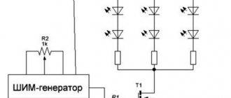
Connecting RGB LED strip
Let's move on to circuit solutions with a low-voltage multicolor RGB tape, which are identical to the circuits of a monochrome tape with a dimmer. The only difference is three negative contacts, unlike one for a single-color tape.
The connection is made through an RGB controller. The length of the ribbon cable is selected taking into account the matching power of the load and the device itself. It is advisable to make a reserve of approximately 15%. The controller has four outputs: the first is a common plus, the other three are minuses, which are connected to the corresponding contacts (R/G/B) on the tape. Below you can see the simplest diagram with a 5 meter RGB strip.
2.1. Connecting an RGB controller
2.2. Connecting the controller and amplifier
If the power of the RGB controller is insufficient, then an additional RGB controller or amplifier is installed. The preferred option is an amplifier, since two single-zone controllers are controlled by two remotes. If we install an RGB amplifier to duplicate signals from the controller, then we can get by with one remote control.
2.3. Connecting multi-zone RGB strip control
This is how multi-zone control of RGB strips is implemented. Connection diagram for LED strip with remote control:
LED pinout
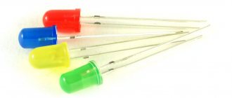
By pinout we usually understand the appearance (body design) of the LED. Each manufacturer produces LEDs in its own housing, depending on the structure and purpose. There is no single standard, as in LED lamps; let me remind you that the most common lamp bases are: e27, e14.
There is no single standard for LED pinout. Each manufacturer does as they see fit. As a result, on store shelves we get a lot of LEDs that differ in shape, appearance, and design.
From the whole set, it is still possible to single out a couple of small groups. For example, the most common simple LEDs are made in a transparent or colored housing made of durable plastic or glass, and have the shape of a cylinder, the edge of which is most often rounded.
More expensive LEDs consist of several parts: a base and a lens. There are conductive tracks on the base, and the lens is made of high-quality material, which serves as a light diffuser. The base is made in the form of a circle or square. Polarity on a square is indicated by a beveled corner. For example, CREE LEDs look like this:
A non-standard pinout may occur when repairing electronic units and cause certain difficulties in determining polarity.
The pinout of the LED determines its polarity, knowledge of which is required for repair or correct installation of the LED in the circuit. It is not always possible to determine the polarity in the usual ways, due to the non-standard pinout of the LED: the special structure of the housing, the thickening of one of the LEDs and other reasons. Therefore, in such cases, whatever one may say, you will have to resort to electrical measurement.
Ways to connect LED strip for home
We would like to add a few more connection methods and their implementation based on our experience. In all options, it is optimal to use a connection diagram for an LED strip with a switch.
- The power supply is mounted in a special hatch or panel. Wires are pulled to it from each reel of tape. The main application is when creating long loops up to 50 meters (10 coils).
- An electrical cable is laid from the power supply. Conductors are mounted from it to the tape fragments. This method is suitable for a project with a large number of short sections.
- Independent power supplies are installed for each section of the flexible printed circuit board. 220 volts are supplied to them in parallel. The method is applicable when there is no space for the power supply, and they are taken directly to the installation site.
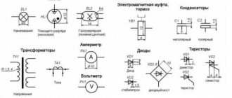
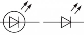
Designation of LEDs on the diagram
The LED in the diagram is indicated as a regular diode with two arrows pointing to the side, indicating the emission of light. The diode itself can be depicted either in a circle or without it. On the side of the nose of the triangle there is a cathode, and on the side of the back of the triangle there is an anode. Sometimes on the diagram you can see the designations of the anode and cathode in the form of the letters A and K or + and -, which respectively mean anode and cathode or plus and minus.
The semiconductor element is signed on domestic circuits with the letters HL (HL1, HL2, etc.) - this is according to GOST. In foreign standards, the LED designation on the diagram is similar to the Russian one. It is signed with a different word - LED (LED1, LED2, LED3, etc.), which translated from English stands for light - emitting diode - light-emitting diode.
Do not confuse the designation of an LED on the diagram with a photodiode. At first glance it may seem that they are the same, however, upon closer examination, a significant difference is visible: the arrows of the photoresistor are directed towards the diode (a triangle with a stick at the sharp end).
The second difference is the letter designation of the photoresistor - VD or VB, which means photocell.
In conclusion, I would like to say that labeling is very important. Knowing its decoding allows you to determine the main parameters of the LED without opening the datasheet. It is unrealistic to remember the markings of all manufacturers, and there is no need; it is enough to know the decoding of the main brands.
Introduction
But let's start a little from afar... Every young specialist who comes to design begins either by folding drawings, or by reading regulatory documentation, or by drawing “this” according to this example. In general, normative literature is studied in the course of work and design.
It is impossible to read all the normative literature related to your specialty or even a narrower specialization. Moreover, GOST, SNiP and other standards are periodically updated. And each designer has to monitor changes and new requirements of regulatory documents, changes in the lines of electrical equipment manufacturers, and constantly maintain their qualifications at the proper level.
Remember Lewis Carroll in Alice in Wonderland?
This is not my way of whining about “how hard the life of a designer is” or boasting “look, what an interesting job we have.” That's not what we're talking about now. Given such circumstances, designers adopt practical experience from more experienced colleagues; they simply know how to do many things correctly, but do not know why. They work according to the principle “That’s the way it is here.”
Sometimes these are quite basic things. You know how to do it right, but if they ask “Why is this?”, you won’t be able to answer right away, referring at least to the name of the regulatory document.
In this article, I decided to structure the information regarding symbols, sort everything out, and collect everything in one place.
Main conclusions
LED is a device that is actively used in any electronic technology. It allows current to flow in only one direction. Therefore, it is important to observe the polarity of the connection. There are several ways to find out which electrode is the anode and which is the cathode - visually, using special instruments, according to technical documentation and by applying voltage. Each of the above methods has its positive sides. The best method for finding polarity depends on the type of LED, the situation, and the availability of a special tool.
How to solder wires to an LED strip?
It is advisable to make solder connections if you know how to solder correctly. The advantage of the resulting joints is greater reliability and resistance to external influences.
If you do not have soldering skills, then it is better to use connectors, which are very easy to use. Their only drawback is the oxidation of contacts at high humidity.
Before soldering, you need to clean and tin the contacts on the board, as well as the ends of the wires using a soldering iron with a power of up to 25 watts and natural rosin. Acid fluxes must not be used. Soldering of conductors is done with one touch of the soldering iron tip, so as not to overheat the soldering area.