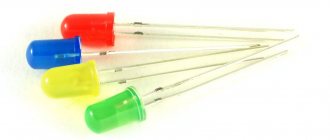
When designing radio equipment, the question of power indication often arises. The age of incandescent lamps for indication has long passed; the modern and reliable radio indication element at the moment is the LED. This article will propose a diagram for connecting an LED to 220 volts, that is, we will consider the possibility of powering the LED from a household AC network - an outlet that is found in any comfortable apartment. If you need to power several LEDs at the same time, we will also mention this in our article. In fact, such circuits are used for LED garlands or lamps, this is a little different. In fact, here it is necessary to implement a so-called driver for LEDs. So, let's not lump everything together. Let's try to figure it out in order.
The principle of reducing the supply voltage for an LED
Two power paths can be selected to supply low voltage loads. The first is, so to speak, the classic version, when the power is reduced by a resistor. The second option, which is often used for chargers, is a quenching capacitor. In this case, the voltage and current flow as if in pulses, and these same pulses must be precisely selected so that the LED and the load do not burn out. This requires a more detailed calculation than with a resistor. The third option is a combined power supply, when both methods of reducing voltage are used. Well, now about all these options in order.
You need to know this
The main thing is to remember safety precautions. The presented circuits are powered by 220 V AC, and therefore require special attention during assembly.
Connecting the LED to the network must be carried out in strict accordance with the circuit diagram. Deviation from the diagram or negligence can lead to a short circuit or failure of individual parts.
When you turn it on for the first time, it is recommended to let the assembly work for a while to make sure it is stable and does not overheat the elements.
To increase the reliability of the device, it is recommended to use previously tested parts with a margin of maximum permissible voltage and power values.
You should carefully assemble transformerless power supplies and remember that they do not have galvanic isolation from the network. The finished circuit must be reliably isolated from adjacent metal parts and protected from accidental contact. It can only be dismantled with the power supply switched off.
Connection diagram for LED to 220 volts (quenching capacitor)
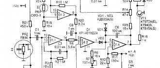
The diagram for connecting an LED to 220 volts does not look complicated, the principle of its operation is simple. The algorithm is as follows. When voltage is applied, capacitor C1 begins to charge, while in fact, on one side it is charged directly, and on the other through a zener diode. The zener diode must match the LED voltage. Thus, the capacitor is ultimately fully charged. Next comes the second half-wave, when the capacitor begins to discharge. In this case, the voltage also goes through the zener diode, which now operates in its normal mode and through the LED. As a result, a voltage equal to the stabilization voltage of the zener diode is supplied to the LED at this time. Here it is important to choose a zener diode with the same rating as the LED.
Everything here seems to be simple and theoretically implemented normally. However, exact calculations are not so simple. After all, in fact, it is necessary to calculate the capacitance of the capacitor, which in this case will act as a damping one. This is done according to the formula.
Let's estimate: 3200*0.02/√(220*220-3*3)=0.29 mF. This is what the capacitor should be like if the LED voltage is 3 volts and the current is 0.02 A. You can substitute your values and calculate your option.
Radio components for connecting an LED to 220 volts
The resistor power can be minimal, 0.25 W is quite suitable (the rating in the diagram is in ohms). It is better to select a capacitor (capacity indicated in microfarads) with a reserve, that is, with an operating voltage of 300 volts. The LED can be anything, for example, with a glow voltage from 2 volts AL307 BM or AL 307B and up to 5.5 volts - this is KL101A or KL101B. The zener diode, as we have already mentioned, must correspond to the supply voltage of the LED, so for 2 volts it is KS130D1 or KS133A (stabilization voltage 3 and 3.3 volts, respectively), and for 5.5 volts KS156A or KS156G
This method has its drawbacks, since with a slight voltage surge or deviation in the operation of the capacitor, we can get voltages much higher than 3 volts. The LED will burn out instantly. The advantage is that the circuit is economical, since it is pulsed. Let's just say, not high reliability, but economical. Now about the combined option.
Connection security
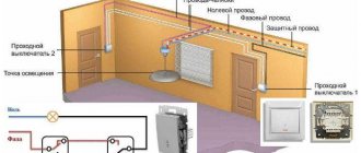
When connecting to 220V, it should be taken into account that the light switch usually opens the phase wire. Zero in this case is carried out common throughout the room. In addition, the electrical network often does not have a protective ground, so even on the neutral wire there is some voltage relative to the ground. You should also keep in mind that in some cases the ground wire is connected to radiators or water pipes. Therefore, when a person comes into simultaneous contact with the phase and the battery, especially during installation work in the bathroom, there is a risk of being exposed to voltage between the phase and the ground.
In this regard, when connecting to the network, it is better to disconnect both the zero and the phase using a batch machine in order to avoid electric shock when touching live wires of the network.
Diagram for connecting an LED to a voltage of 220 volts (quenching capacitor + resistor)
Everything is the same here, except that a resistor was added to the chain. In general, the influence of a resistor can make the entire circuit more predictable and more reliable. There will be less high voltage pulse currents here. This is good!
(...as in the diagram above, a quenching capacitor + resistor is used)
All the pros and cons are similar to the option with a quenching capacitor, but there is no reliability here either. Moreover, the use of a diode rather than a zener diode will affect the protection of the LED when the capacitor is discharged. That is, all the current will flow through the LED, and not, as in the previous case, through the LED and Zener diode. This option is so-so. And here is the last case, using a resistor.
220V flashing LED circuit
And this circuit allows the LED not just to glow, but to blink, which is much more informative and beautiful. Moreover, we put the most common LED indicator here – non-blinking. To do this you need only 5 radio components.
Here, the mains voltage of 220 volts through a diode and a 200-300 kOhm resistor charges an electrolytic capacitor of 20 uF 100 V, and from it a constant voltage periodically opens the dynistor DB3 , causing the LED to flash. The flash frequency will be determined by the capacitance, and the brightness by the resistance of the resistor.
LED Power Questions
- LED STROBOSCOPE ON MICROCONTROLLER
- SMART LED FLASHLIGHT
- HOMEMADE LIGHT FOR SHOOTING
- LED DRIVER FOR HV9910
Connection diagram for LED to 220 volts (resistor)
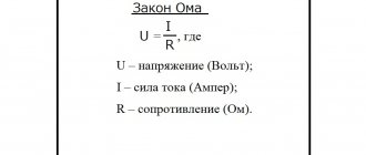
These are the diagrams we recommend for your assembly. Everything here follows classical principles, Ohm’s law and the formula for calculating power. First, let's calculate the resistance. When calculating resistance, the internal resistance of the LED and the voltage drop across it will be neglected. In this case, we will get a small margin, since the actual voltage drop across it will allow it to operate in a slightly more gentle mode than prescribed by the characteristics. So, let's say our LED current is 0.01 A and 3 volts.
R=U/I=220/0.01=22000 Ohm=22 kOhm. In the circuit there is 15 kOhm, that is, the current taken is 0.014666 A, which is quite acceptable. This is how resistors are calculated for these cases. The only thing here will all depend on how many resistors you use. If there are two as in the first diagram, then we divide the resulting result in half.
If there is only one, then of course all the voltage will drop only on it.
Well, as expected, let’s talk about the pros and cons. Plus one and very large, the circuit is very reliable. There is also one minus, that all the voltage will drop across 1-2 resistors, which means it will dissipate more power. Let's figure it out. P=U*I=220*0.02=4.4 Watts. That is, there should be a resistor as much as 4 Watts if the current is 0.02 A. In this case, you should be scrupulous in choosing a resistor; it should be at least 3-4 Watts. Well, you yourself understand that there is no question of efficiency in this case, when 4 Watts are dissipated on the resistor, and the LED can be neglected. In fact, it's almost like a small LED lamp, and only 1 LED lights up.
Important information about capacitors
Storage capacitors are used in a 220 V network:
- as a power supply (if the device is low-power);
- to coordinate loads;
- to smooth out tension;
- to smooth out the current.
Any of them consists of 2 conductive plates and a separating dielectric. The charge accumulates on the plates, but does not move between them. The shape can be cylindrical, flat, spherical. The dielectric is oiled paper, film, glass, mica, tantalum and aluminum oxides, and electrolytes.
Capacitors with protection class X2 are designed to operate at temperatures of -40-+110°C with a voltage of 250-310 V. Capacitance 0.001-2.2 µF, the main advantage is the ability to withstand increased loads caused by switching processes or lightning.
Connecting several LEDs to 220 volts
When you need to connect several LEDs at once, it's a slightly different story. In fact, such variations of the circuit, or rather, stabilizer circuits for LEDs, are called drivers. Apparently from the word drive (English) in motion. That is, it’s kind of like a circuit that starts a group of LEDs into operation. We will not talk about the correct use of this word and about new words that we constantly borrow from other languages. Let’s just say that this is a slightly different option, which means we will analyze it in our other article, “Driver for LEDs (LED lamp).”
Ripple
Ripple is observed in LEDs equipped with a low-quality driver. Most often, the capacity of the built-in capacitor is not enough for normal operation.
How to reduce pulsation
To reduce ripple, it is theoretically possible to power the diode from a powerful storage capacitor (capacitance from 100 μF). But it is expensive and relatively large in size. When replacing it with a resistor, the level of illumination and efficiency decrease simultaneously with pulsation. Plus – extending the life of the LED.
Calculation of the capacitance of the smoothing capacitor
The charge storage device for smoothing out pulsations is most often electrolytic, with a large capacity.
Attention! To connect it correctly to the rectifier, it is important to observe the polarity. If there is no rectifier, you need to connect the working zero to the lamp, the 220 V phase to the storage device. The grounding wire is also connected to the lamp.
To calculate the capacity, the formula is used: C=4.45*I/U-UD, where:
- I – current passing through the diode (in milliamps);
- U=310 V (amplitude mains voltage);
- UD – voltage reduction in the LED lamp.
Video about connecting an LED to a 220 volt network
And now the same thing, but on video, for those who were apparently too lazy to read;)
So, if you want to connect the LED reliably, but with slightly higher energy costs, then the last two options from the article are recommended for your assembly. For all adventure seekers, the first option is just right!
And finally, a calculator for those who are unable to calculate the formulas themselves or are too lazy;)
| Online calculator for calculating the rating and power of a current-limiting resistor | |
| Power supply voltage U, V: | |
| Drop voltage on one LED, V: | |
| Number of LEDs connected in series, pcs: | |
| Maximum permissible current through LED, mA: | |
Example of including an LED in a light switch
One of the common examples of the practical use of an LED in a 220 V circuit is to indicate the off state of a household switch and make it easier to find its location in the dark. The LED here operates at a current of about 1 mA - the glow will be dim, but noticeable in the dark.
Circuit breaker status indication.
Here the lamp serves as an additional current limiter when the switch is in the open position, and will take on a small portion of the reverse voltage. But most of the reverse voltage is applied to the resistor, so the LED is relatively protected here.
Video: WHY YOU SHOULD NOT INSTALL A SWITCH WITH A BACKLIGHT
Nuances in the operation of the voltage indicator
A self-assembled LED indicator, just like industrial devices of this type, can be used to check the presence of voltage. It is not a measuring device, but only indicates the presence or absence of voltage. Having gained some experience with the pointer, you can determine the voltage between two conductors by the brightness of the light-emitting diode. However, for accurate measurements you need to use pointer or digital voltmeters.
Unlike indicators with gas-discharge lamps, the LED indicator cannot be used to find the “phase” by touching one of the probes with your finger. The device has low internal resistance, and this method of searching for a phase conductor can result in electric shock.
What is an indicator screwdriver?
This is a tool designed to detect voltage in the electrical network, including hidden ones. Externally, the model may look like a regular flat-head screwdriver with a transparent handle or have a different appearance. However, a probe in the form of a flat bit is required - this is what is used to check the contacts.
Insulation of the handle is also required - the metal part of the device should not come into contact with unprotected human skin, and any metal parts on the handle should not have direct contact with the probe.
Read also: Abandoned car in the yard
From theory to practice
Current transformer SCT-013
Current transformers are widely used for measurements in a 220V network. You can buy a ready-made transformer and connect it to a microcontroller through a simple analog circuit, but you don’t always have the opportunity and desire to wait for an order, so we will make a homemade one from scrap materials - in the hope that it will turn out faster, cheaper, and more interesting. It is important to say that I did not have the task of greatly optimizing the design - I needed to do it quickly, simply and clearly, so that it would work and not break.
To obtain a sufficient margin of induced emf, but at the same time maintain small dimensions, I used a ferrite ring R36x23x15 PC40 as a magnetic core (this can be bought in a number of radio parts stores for less than 100 rubles). I made the primary winding with a regular power wire, simply passing it through the ring several times. And I wound the signal winding with a thin mounting wire with a cross-section of 30AWG - this makes it easier to make the required number of turns. The density and accuracy of the winding in this case were not important, because It was enough just to detect the switching on of the load, and not to measure the current consumed.
To estimate the margin of induced emf, I calculated the expected voltage on the open signal winding with the load running. To do this, I first calculated the inductance of one turn of wire on the magnetic circuit:
Here is the magnetic permeability of the material (2300 for PC40 ferrite), is the outer radius of the ferrite ring, is the inner radius, is the height. The result was a value of about 3 μH.
Next, I took the rated power of the submersible pump, the activation of which needed to be detected (320 W), and calculated the voltage amplitude on the open winding depending on the number of turns in the primary and secondary windings:
Homemade current transformer connected to a circuit with a test load
After playing with the number of turns, I decided to make 6 turns of the primary winding and 130 turns of the secondary. This resulted in an EMF reserve of about 1.5 V and a current amplitude in the short-circuited signal winding of slightly less than 100 mA, which, when using a 5 Ohm resistor, corresponds to a voltage drop of about 0.5 V. More turns of the power cable would be more difficult to push into the lumen of the ring, and the current in the signal I didn’t want to make the winding too big (since it is made of a rather thin wire). With a smaller number of turns in the primary winding, to obtain a good EMF margin, it would be necessary to greatly increase the number of turns in the secondary winding - which means much more fiddling with the winding and obtaining several times less current for detection.
What it is
An electrical tester is a device that is used to measure and determine the voltage in an electrical circuit. The main difference from a multimeter is the simplicity of the design and use of this unit; it operates quickly and can be used in any conditions.
Photo - resistance tester
There are also more compact probe testers that can be used to measure the voltage level in an outlet or any other electrical device, for example, generators in a car. They differ from standard indicators in their small size, and they also have simpler operating instructions.
Previously, a pointer tester, such as ASKOM, was mainly used. It has a reliable operating circuit, is powered by batteries and provides fairly reliable and accurate operation.