In stock
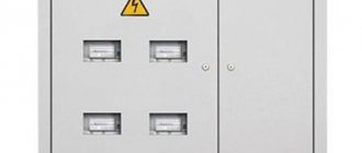
The ASU panel (Input distribution device) is a ready-made equipment consisting of a metal cabinet (dimensions vary depending on the model and installation requirements) and components (electronic components from various manufacturers of electrical products).
The composition of the ASU shield is varied. Depending on the installation requirements of the switchboard itself, the capabilities of the connected equipment or the customer’s budget, the filling of the ASU cabinet can be varied. Therefore, the price for the same model of input distribution device from DEKADA LLC may vary.
Our company provides the opportunity to convert to alternative brands to optimize the customer’s project, taking into account the budget and other features.
The task of the ASU electrical panel is to account for and redistribute incoming electricity into the premises to consumers and other equipment. In addition, like many other electrical panels from the company’s catalog, the ASU panel provides protection against short circuits in the circuit, thereby increasing the safety and security of the equipment.
The protective function against overvoltage is provided by relays and circuit breakers that measure voltage and turn the power supply on and off.
Input distribution board. Main types
There are many differences in the input distribution board. Differences in the degree of protection, in the type of housing, in the installation method, in the maintenance option, as well as in the installation location, the input switchboard can be divided into: ASU1, ASU2 and ASU3.
- The complete set of ARU1 switchboard is installed in basements and on staircase landings;
- Place of installation of ASU2 in switchboard rooms. As a rule, such a cabinet is filled with a professional set of components.
- The VRUZ switchboard consists of a minimum set of electrical appliances and is an integral part of the main switchboard.
Login to the site
The metering of the switchboard is determined by installing an electric meter in it.
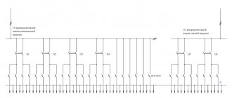
The distribution board diagram can be made using the symbols adopted by the rules of the PUE.
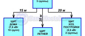
Separate groups are allocated for the extension and bathhouse. In Fig. A characteristic feature of building an ASU circuit at home is the separate power supply of apartment loads and working lighting of common building premises from one input and power consumers from another. Scheme 3 Schematic electrical diagram of the metering and distribution panel, ShchUR. According to established practice, measuring instruments are not installed in the ASU of residential buildings. In accordance with the above, the grouping of outgoing lines by inputs is usually carried out as follows. Drawings included in delivery. The copper bus N is intended for connecting the zero working conductors of the home network. In the input distribution device ASU, the PE and N buses are connected to each other, but according to certain rules.
Types of devices installed in products of the VRU1 series
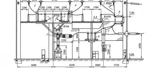
The input circuit depends on the circuit of external supply lines, the number of floors of the building and reliability requirements, the presence of elevators and other power electrical receivers, the presence of built-in enterprises and institutions, and the magnitude of electrical loads. However, their installation is advisable, since the protective device at the input insures protection on the lines extending from the ASU, the failure of which leads to a shutdown at the substation and, consequently, to a call to the emergency service of the power system, and current-limiting fuses at the inputs make it possible to use lightweight equipment on the outgoing lines. Three circuit breakers are planned in the shield, in three groups. Measuring instruments: three ammeters with current transformers and one voltmeter with a switch must be installed at each input. There are more than a dozen schemes.
For buildings above 16 floors, the diagram in Fig. Conventional graphic symbols in electrical diagrams are not defined by any single document. You may also be interested in the following repair articles:.
Read about demand factor in detail. Typical input diagrams. Measurements and accounting Accounting for active electricity consumed by common household consumers is carried out with three-phase direct-connection meters up to 50 A or through current transformers, which are installed on branches to the corresponding sections of the ASU buses. Wire from the voltage limiter arrester. Single-line diagram of house power supply.
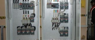
Assembly of the ASU. Production of input distribution devices
900m2 production area houses a COMPLETE production line for input and distribution devices.
The full range of work includes:
— Laser cutting of metal for assembling the ASU cabinet body;
— Welding work and technical control of the product;
— Painting of finished buildings and storage for equipment;
— Calculations and optimization of the project by a full engineering team;
— Quick purchase of all components from leading partner suppliers;
— Assembly of the ASU by experienced and qualified personnel using professional equipment;
— Technical control and delivery of ASU electrical panels to the site is a suitable option.
The company has all types of modern equipment at its disposal to optimize and speed up the process of assembling input and distribution devices.
To get detailed expert advice or order equipment, contact our manager by phone
Input switchgear 0.4 kV
The input switchgear, in most cases, works with three-phase networks.
The voltage in such networks for a 0.4 kV ASU is 220 - 380 V. The abbreviation 0.4 kV means 400 V, despite the fact that the operating value shows 380 volts.
To buy a 0.4 kV input switchgear from Dekada, send the manager an existing project or specification by email to the company.
Using changeover switches
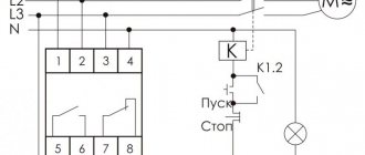
In most cases, for manual control, types of non-automatic switches are used, such as manual starters, switches, controllers and changeover switches with a long service life.
Changeover switches include non-automatic switches equipped with a manual drive for two switching positions - on and off. They have wedge contact and open live parts. When turned on, the knives rotate in the hinges and enter the contact posts.
Features of designing a single-line diagram of a 0.4 kV ASU
The use of a single-line power supply diagram for an ASU is dictated by the simplicity and convenience of its design, as well as the frequency and prevalence of its use. It is this scheme that is one of those important fundamental points on the basis of which electrical installation work is carried out and a power supply system is created.
Determining the number of ASUs and their installation locations and, accordingly, placement on a single-line diagram depends on the load calculations performed and the distribution of electricity consumers into groups. Such a distribution provides a very important advantage in the sense that if any problems or malfunctions occur in the electrical system, for example, a short circuit, there will be no need to de-energize the entire network; it is enough to disconnect only the problem area from the power supply. Another compelling argument in favor of such a division of consumers is the steady increase in the number and power of modern household appliances; bringing them all into one group is fraught with the threat of overloads and accidents.
The most common and optimal option for distributing consumers is to group them into three groups with connections to electrical networks - power electrical equipment, sockets and switches, lighting fixtures. The first group includes the most powerful consumers, which are usually resource-intensive washing machines, electric stoves, heating devices, and so on. In private homes, it is also advisable to include in this group devices responsible for organizing an autonomous power supply in cases where power outages occur.
Therefore, when working on the design of a single-line 0.4 kV circuit, it is necessary to immediately clearly determine the installation location of all input and distribution devices, indicating the power consumption, and indicate all this on the diagram.
Below you can use the online calculator to calculate the cost of designing power supply networks:
Option 3
As I wrote above, all groups of sockets must have protection against current leakage, that is, they must be protected using an RCD. The third version of the circuit presents an introductory RCD, which is installed after the meter. An RCD cannot be installed before the metering device, since it will need to be sealed, which inspectors do not want to do. That's why they only allow it to be placed after the counter.
To protect people, you need to use an RCD with leakage currents of 10-30mA. This is a safe current for a person, in which he is able to withdraw his hand and not receive any injury. The option using one 30mA RCD at the input has one drawback. When it is triggered, the entire apartment, house, etc. is switched off. Also, if the network is highly branched, then the RCD may trigger falsely due to natural leakage currents that are present in every household appliance.
In this embodiment, phase and zero are supplied to the input contacts of the RCD. Next, from the output contacts, the phase is supplied to the circuit breakers, and the zero is supplied to its zero bus. Remember that the zero before the RCD and the zero after it cannot be combined with each other, that is, connected to one bus. Otherwise, you simply will not arm the residual current device, as it will immediately turn off.
What elements does an electrical panel consist of?
It is necessary to purchase the components of the electrical panel immediately, so as not to subsequently waste time and not travel to the electrical store several times a day. The power of the shield is determined, it is 15 kW, which means that the maximum power consumption will not exceed 15 kW/h.
Electrical panel of a private house, list of elements:
- Electric energy meter. The meter is the first element that must be installed in the panel. The best solution would be to purchase an electronic device designed to connect three phases. Such measuring instruments have high accuracy and a long service life. All information is displayed on a digital screen. Electronic meters can be programmed to operate in several tariffs.
- Electrical shield. Now in stores there are a large number of electrical panels of various sizes and designed for a certain number of elements. The price of the product varies depending on the presence of a DIN rail, a built-in lock, as well as an inspection window (especially for taking readings from the meter). You should pay attention to protection from dust and moisture, its level should be at least IP 54. Dimensions - 445 × 400 × 150, and a wall thickness of 1 mm.
- Input circuit breaker. You should purchase a three-pole machine, because the voltage supplied to the house will be 380 V, which means the presence of three phases.
- Residual current device (RCD). It is required to be installed, since it is a protective element when a dangerous potential appears on the body of an electrical device.
- Circuit breakers. The amperage should be selected based on the consumer load, which will be discussed below.
- Voltage relay. Protects household electrical appliances from power surges. Many users install a relay, but it is not a required element. Also now widely used is the surge protection device (SPD). For example, when lightning strikes an overhead power line, the voltage in the house will reach high limits, which will be destructive for all equipment. The SPD will turn off the network in time, but, like the voltage relay, it is not installed often.
- Measuring instruments. They are also an optional element of the electrical panel. Measuring instruments include ammeters and voltmeters, often combined into one product.
Distribution panel assembly diagram
In order for the electrical wiring to be safe and able to withstand the load, you need to study the installation diagram of the electrical panel. The entire hierarchy must be indicated on the project. The distribution panel assembly diagram is quite simple.
In addition, all automatic equipment must display the full rating and protection class. Now is the time to study visual diagrams of the switchboard of a private house, apartment or cottage. If you are interested, then you can read about the connection diagram for a 380 Volt outlet.
Sequence of correct installation of an electrical panel
To ensure that the electrical panel in your home is installed correctly, you should use only high-quality electrical products, as well as consumables. Only after installation is completed, operating voltage is supplied to the panel.
The correct assembly of a three-phase electrical panel has the following sequence:
- Installation of an introductory machine. The device rating must cover the maximum power consumption. Since 3 phases will be brought into the house, the voltage between them will be 380 V, it is necessary to install a three-pole circuit breaker. To save money, it is not recommended to install 3 single-pole circuit breakers and connect them with a special strip. The input machine is installed in the upper left corner of the shield and is marked accordingly.
- After the introductory machine, it is necessary to install an RCD. The rating of the device must correspond to the rating of the input switch. You should also pay attention to the cut-off current - the lower this indicator, the faster the RCD will turn off the network. There are differential circuit breakers that include protective functions against short circuits and shutdown the network when a leakage current occurs (RCD and standard switch). It is easier to use such a product, but its cost is quite high.
- To the right of the RCD, at a short distance, a zero bus is mounted. Modern busbars provide a plastic dielectric between the copper strip and the shield body. This is done so that if the zero burns out and a phase gets on it, the electrical panel does not end up under life-threatening voltage.
- Measuring instruments and voltage relays can also be placed on the strip with the input circuit breaker, RCD and zero bus. If you install a voltmeter and an ammeter in a three-phase network, then you must select products that display both linear and phase loads. And also capable of showing data on each phase separately.
- The lower DIN rail contains automatic switches for power and lighting lines. In order not to get confused and not constantly look at the rating of the machines, lighting line products should be located at a short distance from the power switches.
After assembling the shield, you can mount it to the wall and connect the wires from consumers to the machines. An example of an electrical panel diagram, the number of machines can vary depending on the wishes of the owner.
If the electricity metering panel with a voltage of 380 V is not located on the street, then it is first installed in front of the input machine. But installing a device to monitor electricity consumption in the house is inconvenient, so inspectors (to save time and the absence of owners) must take readings on the street.
Option 4
In this version of the circuit, there is a 100-300 mA fire protection RCD at the input, and then some groups are protected by individual 10-30 mA RCDs. To prevent simultaneous operation of the input and group devices, it is recommended to install a selective RCD at the input. It has a time delay for operation and is designated on the case by the Latin letter “S”.
Notes
- The color identification of conductors in this ASU is made in accordance with the requirements of GOST R 50462–92, which was in force from January 1, 1994 to December 31, 2010. Currently, the requirements of GOST 33542–2015 should be followed.
- Type A UDT operates with sinusoidal and pulsating direct currents.
- This ASU takes into account “Changes 1”, which were adopted in March 2017 by the International Electrotechnical Commission to the IEC 60364-4-41:2005 standard (on the basis of which the currently valid national standard GOST R 50571.3-2009 was created). Let me remind you that these “Changes 1” require mandatory additional protection by means of UDTs with a rated differential current not exceeding 30 mA for all final electrical lighting circuits, the lamps of which are located in domestic premises. This requirement is logical, since in residential premises lamps are often installed within the reach of a hand. Moreover, the lamps are used by ordinary people.
Option 1
This is the simplest circuit of an input panel with an electricity meter. It shows the TN-S grounding system, that is, when separate independent neutral working and neutral protective conductors come from the power source. In this single-phase switchboard circuit, there is a two-pole circuit breaker at the input.
Here and in subsequent diagrams, the ratings and characteristics of protective devices are chosen arbitrarily. Yours may differ, but the very essence of the connections between circuit breakers and other protective devices remains the same.
After the opening machine there is a counter. To register it, the input switching device and the electricity meter itself must be sealed. Next come single-pole group circuit breakers. The phase is always supplied to the circuit breakers, and the zero to the zero bus. It turns out that all neutral working conductors of different groups are combined with each other, and phase conductors are switched using automatic machines.
This version of the scheme is the simplest and is very often found at various sites.