Classification
There are several classifications of reactor plants based on various features. Depending on the operating conditions, there are switchgears (to enlarge the diagram, click on it):
- open type (OPU) – equipment located outside buildings or other shelters. Such devices are easy to check for serviceability, easy to locate and make changes, but they take up a lot of space and require increased protection from the adverse effects of atmospheric and climatic factors;
outdoor switchgear - closed type (CLU) – are located in protected facilities and take up much less space. The disadvantage is that it is difficult to maintain due to its more compact location. Typical for the conditions of an industrial enterprise or city.
ZRU
Video about outdoor switchgear:
The specified RUs may differ according to the following criteria:
- division method - in the form of separate sections or with bus systems. Bus systems can switch consumers from one section to another. If separate sections are performed, the consumer is connected personally;
- device connection diagram - ring and radial method. With a ring circuit, one object is connected to several switches. If a radial circuit is arranged, consumers are powered through busbar disconnectors using one switch. The radial method is simpler, and the circular method is more reliable and practical for ensuring the operation of electrical equipment;
- the presence of bypass elements - this system allows you to repair equipment without disconnecting subscribers.
In addition to the listed varieties, SF6 equipment is used, which involves placing the installations inside a space filled with a special composition with high safety properties.
Design – switchgear
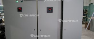
Also used are complete switchgears (SGD), consisting of standard modules placed in cabinets. Such elements contain the necessary safety blocks, switches and other components and are supplied ready-made, which does not require packaging. If the device involves outdoor installation, it is called KRUN. Such a module provides appropriate protection.
KRUN
Video about KRU:
Depending on the voltage class, network parameters, number of subscribers, the following distribution devices are provided:
- prefabricated chambers;
- complete distribution devices;
- points for maintaining commercial records;
- complete transformer substations;
- points for automatic voltage regulation;
- distribution board panels;
- low-voltage distribution panels;
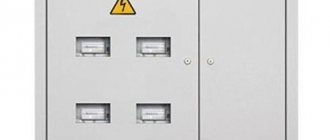
- outdoor electrical energy metering cabinets for private homes;
- devices for monitoring parameters.
More details about the features of the switchgear according to voltage characteristics.
You can find more information about RU in this book (about RU from page 392): Open book
RU up to 1 kV
These elements are completed and placed in special cabinets or panels. Their purpose may include transmitting energy to consumers or powering their own equipment.
In addition to the main systems, such modules can be equipped with additional devices:
- current transformers and electrical energy metering devices;
- indicating circuits and position indicators of switching switches;
- measuring units to determine the technical characteristics of circuits;
- signaling and protective devices against ground faults;
- devices for automatically switching on backup circuits;
- remote control systems.
Low-voltage switchgear may include DC modules that distribute voltage from power sources to equipment and consumers.
Purpose and classification of electrical substations. Decoding of KTP,TP.
The following types of electrical substations are distinguished:
TP - transformer substation. Used to convert electricity of one voltage into electricity of another voltage. The main equipment of such a substation is 2- and 3-winding transformers.
PP – converter substation. Used to convert AC electricity into DC electricity. For this purpose, special units are used - converters, for example, rectifier units.
GPP is the main step-down substation. This is the main substation of the enterprise, which receives electricity with a voltage of 35 to 220 kV from the regional energy system and distributes it to consumer substations or powerful electrical receivers with a voltage of 6 to 35 kV.
PGV - deep input substation. This is a substation that receives electricity with voltages from 35 to 220 kV from the regional power system. Its distinctive feature is its proximity to the powerful energy consumers of the enterprise.
PP - consumer substation. This is a transformer substation that receives electricity with a voltage of 6 to 20 kV and distributes it to consumers with a voltage of 0.4 to 1 kV. If we talk about industrial enterprises, then workshop substations belong to this type.
RU - switchgear. It is an open or closed electrical installation that receives and distributes electricity.
RP - distribution point. This is a distribution device that receives electricity from the main step-down substation or district substation with a voltage of 6 to 20 kV and distributes it to powerful receivers and consumer substations.
TsRP - central distribution point. This is a distribution point that receives electricity from the district substation and distributes it to workshop substations.
The above electrical substations serve as power sources in the enterprise’s energy system. To ensure their uninterrupted operation, and therefore to prevent accidents and stoppages of the production process, it is necessary to regularly test transformers and other power equipment.
Content
hide
1 Decoding of KTP
2 Operating conditions for complete transformer substations
3 Symbols of KTP
4 Types of substations
5 Design of KTP
6 Equipment
Decoding of KTP
The definition of KTP in electrical engineering means a complete transformer substation. The concept of completeness in TP is dictated by the design feature of manufacturing - the production of a full-fledged substation for outdoor installation with a set of working units that are assembled in the form of kits into a single power supply system.
KTP
Often, a structure consisting of a housing, electrical components for removing and converting energy, and metering panels is delivered to the installation site in a fully or partially assembled form, which reduces time costs and facilitates the installation process and its commissioning.
Modern PTS allow solving several problems at once:
- Reception of electricity from three-phase alternating current power lines with a nominal voltage of 6 (10) kV and an industrial current frequency of 50-60 Hz.
- Stepwise transformation of the received energy into alternating current with a voltage of 380 V (0.4 kV) and a frequency of 50-60 Hz; one phase out of three is allocated for household consumers.
- Distribution of converted electricity to end users connected via a ring (continuous distribution line in the form of a closed loop) or radial connection scheme.
The capacities of power electrical installations are designed to supply energy to medium and large consumer facilities, including:
- construction sites;
- industrial enterprises;
- residential areas, microdistricts, villages;
- communal and municipal services;
- agricultural and farming facilities.
A wide variety of designs, configurations and structures that fit most correctly into the climatic and technical operating conditions of the complete device allow you to choose an option suitable for a specific facility.
Operating conditions for complete transformer substations
Full uninterrupted operation of the installation with minimal losses during the transmission of electricity is possible subject to the rules of installation, commissioning and conditions corresponding to the climatic design in accordance with GOST 15150 U (moderate) or UHL (moderately cold):
- operating temperature range from -45°С to +45°С (for current converters with oil insulation);
- operating temperature range from -1°С to +40°С (for current converters with dry insulation);
- atmospheric pressure – 86-106 kPa;
- relative air humidity – up to 80% (at air temperature up to +20°C);
- wind gusts up to 36 m/s.
KTPs are designed to be located at an altitude of up to 1 km relative to the sea line. In practice, there are isolated cases of exceeding this parameter, but manufacturers are not responsible and do not provide warranties for such situations.
It is strictly forbidden to operate the installation:
- during seismic activity;
- in explosive environments;
- when there is dust in the air that transmits current discharges;
- under conditions of a high content of chemically active volatile compounds and vapors, which have a destructive effect on the metal and insulating materials of the product.
Installation work consists of placing a pre-assembled and factory-assembled station, equipped with dedicated transport and lifting devices, on a flat surface made of brick or concrete. Before commissioning, a final audit of all power plant complexes is carried out. The service life of the unit is at least 25 years.
Symbols of KTP
Explanation of symbols includes the following parameters:
- type of execution;
- connection type;
- transformer power;
- letter designation of the product;
- classification of input from the HV side;
- classification of output from the LV side;
- number of transformers used;
- HV voltage ratings;
- LV voltage ratings;
- climatic implementation according to GOST 15150 and placement category.
Manufacturers reserve the right to change (add or delete) some product data.
Types of substations
Transformer substations are classified according to several parameters:
By type of electrical connection to high-voltage power lines:
Dead-end - Characterized by the ability to connect to only one highway.
Pass-through - The power source is two highways.
At the installation location:
In-shop (KTP-VC)
For use indoors in close proximity to the equipment being used.
Pole (KTPS) - For installation on power line supports.
Kiosk (KTPK) - For outdoor use, they look like a compact metal cabinet.
Mast-mounted (KTPM) - With an open system, for fastening at a height of up to 7 meters from ground level. Insulated with sandwich panels.
A type of kiosk substations for operation at low temperatures and in conditions of increased windiness.
By type of inputs and outputs:
- cable;
- air.
By the number of current converters used:
- single-transformer;
- two-transformer.
The power of a substation is selected individually for a specific facility, based on the parameters of the total power consumption. In the segment of high-voltage power plants, there are options with power transformer power from 25 to 4000 kVA.
KTP design
KTPN design
Traditionally, a KTP is a set of component units distributed in localized modules, which are combined into a common housing. Based on their structural components and location, stations are divided into ground-based, mast-based and integrated. The first ones are equipped in cases made of metal, reinforced concrete or insulated sandwich panels. Mast ones are placed on vertical poles and can have a lightweight metal structure with partially open elements. To make technical work accessible, a special staircase and platform are provided.
To service the station there are doors or swing gates with a central lock and a locking system. The body is equipped with technical openings and hidden blinds to organize natural thermoregulation and ventilation of the system.
Equipment
The equipment of a transformer substation depends on the characteristics of a particular power supply facility, its power, conditions of use and the functions assigned to it.
The classic (standard) delivery set includes a design with built-in modules:
- RUVN – 6 (10) kV switchgear – a set of units for receiving high-voltage voltage and protecting equipment from overvoltage and high currents;
- RUNN - 0.4 kV switchgear - a set of elements for switching, protecting and measuring network parameters on the low-voltage side;
- power transformer - for converting high-voltage current - oil type TMZ, TMG, dry type - TSZN, TSZGL;
- busbar - a set of conductors, bus connections and flexible connections.
Each cell performs its functions:
- accounting;
- protective;
- measuring;
- blocking;
- switching;
- distribution;
- voltage transmission.
The following are used as additional and auxiliary components:
- lighting system - internal, external, emergency - for safety of maintenance and timely indication of an emergency situation;
- ventilation system - forced or forced - to prevent the risks of overheating and reduce humidity levels;
- heating system - convector, manual or automated - to maintain the temperature conditions of the devices;
- blocking systems against accidental or intentional penetration of high-voltage components;
- an automated complex to warn the operator in case of fire or burglary.
To cable connect a package transformer substation to the nearest power line, it is equipped with air entry equipment - insulators (support, pin and bushing) and voltage limiters. To ensure the safety of operating personnel, a mandatory grounding loop is provided.
Share link:
You might be interested in:
- Surge suppressor - its types and capabilities
- What is an ASU - decoding and packaging
- Electricity meters. Catalog and description
- Energy-saving household appliances and light sources
Installation of substations of industrial enterprises - Installation of switchgear up to 1000 V
Page 17 of 17
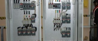
6. INSTALLATION OF SWITCH DEVICES WITH VOLTAGE UP TO 1000 V
The main type of switchgear with voltages up to 1000 V are switchboards. With their help, they supply power to external loads and the substations’ own needs. Distribution boards vary in layout and in the devices and devices installed in them. Panels are assembled from panels or cabinets interconnected in quantities and combinations corresponding to the design scheme and the construction part of the panel room. The panel (or cabinet) is a completely finished element of the switchboard, and the switchboard as a whole is a complete electrical device. The panel is a metal structure (frame with a front panel) on which devices and devices for switching, measuring and protection are installed. The panels of the switchboard are connected by busbars and secondary circuit wiring, to which the equipment mounted on the panels is connected. They are divided into inlet, linear and sectional depending on the purpose of the devices installed on them, as well as end ones, the purpose of which is the protective and decorative covering of the sides of the outer panels of the shield. Panels of all series are based on a single frame made of bent steel sheets 2-3 mm thick with parts made of bent steel profiles for mounting devices and the same design: two front posts, an upper front sheet for measuring instruments, doors for servicing devices installed on the frame inside, two rear pillars, transverse and longitudinal connections. The handles of the machine drives and switches are brought out onto the panel façade through rectangular holes. Installation of panels begins with marking the installation location of the foundation frame, which must be installed at the first stage of installation work. The passages between the wall and the shield, the symmetrical arrangement of the longitudinal and transverse axes of the shield to the switchboard room, the interface with cable ducts and openings, taking into account the level of the finished floor, are checked. The panels are installed after completion of construction and finishing work on the foundation frame, aligned in horizontal and vertical planes and temporarily secured. After installation, connecting the blocks or panels together and alignment, the shield is finally secured with bolts or welding. They install busbars and install devices that arrive in separate packaging.
REFERENCES Rules for electrical installations. Sec. IV. Switchgears and substations. — — 5th ed. - M.: Atomizdat, 1977. -99 p. SNiP Sh-33-76. Electrical devices. Instructions for installation of complete switchgears for voltages up to 10 kV. — Moscow: Energy, 1979. Instructions for transportation, storage, installation and commissioning of transformers for voltages up to 35 kV without revision of their active parts. - Moscow: Informenergo, 1971. Smirnov V.N., Sokolov B.D., Sokolova N.B. Installation of electrical installations. - M.: Energy, 1976. - 472 p. Elkin Yu. S. Installation of electrical machines and transformers / Ed. B. A. Delibasha, A. D. Smirnova, B. A. Sokolova. - M.: Energy, 1979, - 200 p.
- Back
After this, the installed chambers and cabinets are connected by busbars, for which the previously prepared busbars are secured to insulators; Branch busbars are connected to prefabricated busbars. Then, instruments and apparatus that are dismantled for the duration of transportation are installed and connected in accordance with the diagrams.
The finally installed cabinets, chambers or units are cleaned of dust and dirt and the equipment inspection begins. At the same time, they check all bolted connections, the presence of lubricant in the rubbing parts, the adjustment of switches, disconnectors, drives, contacts of KSA and other devices, as well as the operation of withdrawable carts, disconnecting contacts, etc. Then the cables are connected, all metal structures, grounding, and reinforcement are painted equipment and tires and apply inscriptions to cabinets and cameras.
Installation of the 0.4 kV switchgear is also carried out in two stages. The boards from which the 0.4 kV switchgear are assembled are delivered to the installation site, as a rule, in blocks (usually up to 4 m long) or in separate panels (cabinets), so the installation of the 0.4 kV switchgear is in many ways similar to the installation of the 6-10 kV switchgear . Minor differences in installation are mainly due to the requirements for the construction part and equipment adjustment. Thus, in the panel room, before installation begins, not only basic construction, but also finishing and plumbing work must be completed, including whitewashing, painting, ventilation, heating and electric lighting, and locks must be installed on the doors. When inspecting and adjusting the equipment of the switchboards, the mechanical strength of the switches is checked (by turning them on and off 30 times) and ensuring a tight fit of the knife switches and the caps of the tubular fuses to the contact jaws. In addition, check the insulation resistance of all connected secondary circuits.
Installation of PTS. Complete substations arrive at the installation site fully assembled or in blocks with installed and tested equipment and adjusted equipment. Typically, the PTS is installed on a gravel-filled site or on a concrete foundation, which is prepared in advance.
Installation of indoor PTS, as a rule, begins with the installation of inspected and tested power transformers. Then, high-voltage input cells and a low-voltage panel with input cells from the transformer, outgoing lines and sectioning are installed. Cells and transformers are interconnected by secondary circuits and buses and connected to a ground loop. After this, the ends of high-voltage and low-voltage cables are inserted into the cells, cut and connected.
Installation of outdoor PTS (KTPN) is somewhat different from installation of PTS. Since the KTPN is usually a single structure, after unpacking and inspection it is installed on the foundation as a whole, and only then the power transformer is rolled into place. If necessary, a disconnector is installed on the overhead line support. The substation is connected to the ground loop and the necessary tests and measurements are performed. After this, connect the cables or wires of the overhead line and prepare the KTPN to receive voltage. KTPN of other designs, consisting of individual cells, are mounted in the same way as KTP.