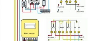
Electrical machines convert mechanical energy into electrical current and vice versa. The vast majority of electrical devices operate according to a simple scheme: under the influence of mechanical energy, electricity is generated, which in turn causes the movement of machines, machines, mechanisms, and rolling stock. In the transport industry, a traction motor is well known for driving the wheel pairs of cars. Using them in generator mode makes it possible to slow down the train. The braking process occurs due to the load generated in the process of converting the mechanical energy of a train in motion into electric current.
The emergence and development of traction devices
At the very beginning, when electric transport first began to be used, commutator traction motors were installed on all types of rolling stock. At the same time, energy transfer was carried out according to the simplest scheme, so the units could be easily controlled in any operating mode. Technical and mechanical characteristics fully met all transport specific requirements.
However, during operation, the DC traction motor revealed a number of shortcomings. First of all, this is the collector itself, equipped with movable contacts - brushes, which requires regular maintenance. The measures taken to reduce sparking and increase switching reliability have largely complicated the design of the engine. As a result, its dimensions have increased noticeably, but the maximum rotation speed has remained at the same level.
The direction of power technology based on high-speed semiconductors gradually developed. This made it possible to replace the rheostat system used in collector units with a pulse system, which is characterized by increased reliability and efficiency. Subsequently, an asynchronous traction motor began to be installed in carriage pairs as a drive mechanism.
The main problems encountered when operating asynchronous motors are considered to be complex adjustments. Certain difficulties arise when using electric braking, when motors based on a squirrel-cage rotor are used for these purposes. At this time, the development of more modern traction drives based on synchronous units in which a rotor is installed on permanent magnets is underway.
Since collector units are still widely used in railway transport, their general structure and operating procedure should be examined in more detail.
Electric locomotive equipment
Electric locomotives of both systems usually have a unified body in which all equipment is located. Passenger electric locomotives have their own specific body design.
Pantograph
On the roofs of electric locomotives there are pantographs - this is a tubular structure, at the very top of which a pantograph skid is fixed through a carriage; carbon or carbon-ceramic inserts are installed in the skid, which slide along the contact wire, transmitting current to the pantograph and then to the power circuits.
Other materials can be used instead of carbon inserts. On the pantographs of DC electric locomotives, as a rule, two skids are installed to improve current collection. The pantograph rises when air is supplied from the control circuits to the pneumatic cylinder, overcoming the force of the return springs. When the pantograph is lowered, the air from the cylinder escapes into the atmosphere and the return springs lower the pantograph onto the roof. A faulty pantograph can be disconnected from the power circuit using a manual disconnect switch.
Auxiliary machines
It should be noted that air for any electric locomotive is a very important element in its operation. Without air, you cannot lift the pantograph, connect power contacts, etc. All electric locomotives have auxiliary compressors that can pump up the pressure in the control circuits to the value necessary to raise the pantograph.
Electric locomotives of both current systems have electric motor-fans for cooling the electric motor and other devices, motor-compressors for pumping air into the main reservoirs of the locomotive, and from there into all systems of the electric locomotive and automatic train brakes.
Electric locomotive engine room
All electric locomotives are controlled through controllers (of different designs) from the driver's cabin and are equipped with all the necessary equipment for driving the train (spotlights, driver's cranes - condition No. 395 and condition No. 254, HF and VHF radio stations, buffer lights, bathrooms, etc. ). On the roofs of electric locomotives, in addition to the pantographs mentioned above, there are fan shutters, antennas, insulators, shunts, busbars and other equipment. Passenger electric locomotives are equipped with heating systems for passenger cars (3000 V).
Purpose and structure of the bed
Each traction motor is equipped with a frame, used primarily as a magnetic circuit through which the magnetic fluxes of the main and additional poles pass. It also serves as a location and fastening place for poles and bearing protection.
When heavy loads are present, the frame is usually cast from steel or welded from thick electrical steel sheets. Thanks to this design, the required mechanical stability and high magnetic permeability are created. The walls usually have a thickness that provides a specified level of magnetic induction, and its dimensions are oriented towards the cross section of the main poles and are not less than 50% of this size.
The presented figure shows the location of the frame (1) relative to other parts and components - the pole core (2), the field winding coil (3) and the pole shoe (4). There is an air gap (5) between all elements and the anchor. The diameter dimensions from the inside of the frame are calculated so that this space can accommodate the armature, the main and additional poles and their windings.
The locomotive's traction motor may have a cast steel frame with reduced weight and a reduced cross-section oriented toward the axes of the main poles. This makes it possible to evenly distribute the magnetic flux coming to the frame from the main pole.
Design features of TED
Powerful stationary electric motors are structurally much simpler than their traction counterparts, which is generally understandable. They do not have to work in such difficult conditions, the installation of such motors does not require complex solutions, and there are no strict requirements for dimensions. For the TED, it was necessary to develop special frames and other mounting equipment; the designers had to take into account the limitations of the engines in terms of length and diameter. It is also necessary to take into account that traction electric motors of railway and passenger urban transport, as well as cars, are forced to “work” in extremely unfavorable conditions. These include weather factors (the influence of humidity, dust, temperature fluctuations), and road factors, when the power of the motor changes quickly and in different directions, with frequent engine starts. Thus, in the starting mode, currents can exceed the rated ones by two or more times.
Traction electric motors are forced to work in conditions of shaking and constant shocks, in conditions of increased mechanical, electrical and thermal load. Therefore, when developing motors, much attention is paid to increasing the mechanical strength of parts and their connections and the reliability of electrical components, improving the insulation of current-carrying elements (from the point of view of heat and moisture protection), and ensuring reliable switching of all parts of the engine.
There are also certain industry specifics. Thus, for traction electric motors installed on mine electric locomotives, it is necessary to ensure compliance with the requirements for protection against the possibility of fire or explosion.
Due to the above, TEDs are classified as electric motors of maximum use.
Main poles
A traction motor operating on direct current includes in its design an excitation winding, where a magnetomotive force appears, which in turn creates a magnetic field. The winding consists of coils placed on the cores of the main poles. On the side of the core directed towards the armature, a pole piece, also known as a shoe, is installed. With its help, the magnetic flux is evenly distributed over the entire surface of the armature. The listed parts are marked in the previous figure along with the frame.
In practice, a circuit that includes a pole core and a pole shoe is quite rarely used. As a rule, they combine into a single whole and form the main pole. Due to this, in the core of the pole there is a decrease in vortex flows caused by the action of pulsations of magnetic induction in the tips due to the serrated surface of the armature.
To assemble the pole, lacquered steel sheets are used, which are then put under a high pressure press. Bolts or special rivets are passed through the core to tighten the entire structure. Their uniform distribution makes it possible to successfully withstand the elasticity of compressed strips. The poles are fastened to the frame using bolts or studs.
Operating modes
Operating modes
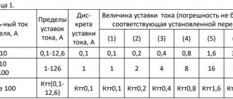
TED - long-term and short-term. Continuous mode - operation for an unlimited time at rated voltage with the highest current strength, at which the temperature of the windings reaches the maximum permissible. For traction motors used for electric braking, rated continuous modes are set at the lowest and highest permissible voltages, at rated power and rotation speed. Nominal short-term modes are set for operating periods of 15, 30, 40, 60 and 90 minutes.
The greatest distribution is on EPS. Russia and foreign countries received collector TEDs of direct and pulsating current; the first - on electrified lines with constant voltage, the second - on lines with alternating voltage of industrial frequency. Single-phase collector alternating current motors are used less frequently (in the USSR such motors were not used for traction); they are connected directly to the secondary winding of the transformer. In a number of Western European countries, on old sections of electrified railways. d. traction motors are powered by alternating current with reduced voltage in the contact network with a frequency of 162/3 Hz. In the 1950s On electric locomotives (France), single-phase collector electric motors were installed, operating at an industrial frequency of 50 Hz. These motors did not become widespread due to poor commutation, the complexity of the design of the multi-brush current collection unit and strong pulsation of low torque, as well as due to their large weight and inability to operate in braking mode. Single-phase collector TEDs became especially unpromising with the advent of EPS, which used semiconductor rectifiers. Thanks to the creation of semiconductor converters that are acceptable in terms of weight, size and energy parameters, starting in the 1970s. began to use asynchronous and synchronous brushless electric motors of three-phase current.
Purpose and arrangement of additional poles
Each traction motor with a power of more than 1 kW is equipped with additional poles in order to reduce the number of sparks appearing on the brushes. Their device is very simple, including a core (1) and a coil (2), where a copper conductor is used in insulation. Its cross section is calculated based on the operating current of the motor, since this coil and the armature winding are connected in series to each other.
The steel core is made in the form of a monolithic structure, due to the absence of eddy currents in it, since the magnetic induction is very small. The location of installation of additional poles is determined by the gap between the main poles, and fastening to the frame is carried out with special bolts. The size of the air gap under them significantly exceeds the gap under the main poles. Its adjustment is carried out using special plates made of magnetic or non-magnetic materials, and the final value is determined when the DC traction motor is set to switch when the minimum number of sparks is reached.
What types of electric locomotives are there?
Freight electric locomotives usually operate in a two-section or three-section design; two two-section electric locomotives can also be connected. All intersection connections are made by cables (joxes), electric locomotives are controlled from one remote control, this is called a system of many units.
Currently, electric locomotives are being built in three-section and four-section versions, with the ability to enter all sections when moving; the intermediate sections no longer have control cabins and are called booster. These are the general similarities between electric locomotives of the two current systems. We will look at the differences in the following articles: electric locomotives of direct current, alternating current, dual power.
Anchor and manifold
The armature consists of a shaft, core, windings and commutator. The core configuration is made in the shape of a cylinder, and it itself is made of thin stamped sheets of electrical steel. To insulate the sheets, varnish or paper is used. In a compressed form after assembly, the core is fixed with pressure washers. Thanks to the design of the core, it is possible to compensate for the influence of eddy currents and reduce the leakage of electricity in it. Cooling of the TED is carried out due to special ventilation channels arranged in the core.
For armature windings, a copper conductor of round or rectangular cross-section is used. It is placed in the recesses of the core and is qualitatively insulated from it. The entire winding is divided into sections, the ends of each of them are connected to the collector by soldering.
The design of each collector includes an active component and a fastening system. The copper collector plates (7) are insulated using special gaskets. The armature winding wires are soldered to the protrusion at the end of the element (5). The edge of the plates located at the bottom (6) after assembly is clamped using two pressure rings (3). These rings are also insulated, and the insulation itself is recessed 1.5 mm inside the sliding surface of the collector.
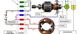
Synchronous (valve) motor
Synchronous (valve)
The operating principle of a TED is similar to a direct current machine, in which the mechanical collector is replaced by a system of power controlled valves of the converter installation. There is a multiphase winding on the stator, and a DC excitation winding on the rotor, to which electricity is supplied through special rings and brushes. The valves are switched at low speeds based on signals from rotor position control sensors installed inside the electric motor, or by back emf at a higher speed. Continuous rotation of the rotor is ensured by alternately switching the leads of the stator winding according to the converter valve control program. The valve TED is regulated by voltage, frequency and excitation current (three independent control channels). Microprocessors can be used in the control system for valve-type electric motors.