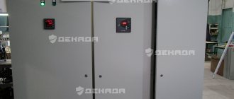
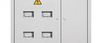
Input distribution devices VRU 1, VRU 1M, and VRU 3 are designed for distribution and metering of electricity in networks of 380/220 V three-phase alternating current with a frequency of 50 Hz with a solidly grounded neutral, as well as for line protection during overloads and short circuits. Input and distribution devices are equipped with single-sided service panels and can be single-panel or multi-panel. The devices are supplied complete with equipment and all internal inter-panel connections.
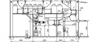
The ASU busbar can withstand a short-circuit shock current of 10 kA without damage.
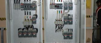
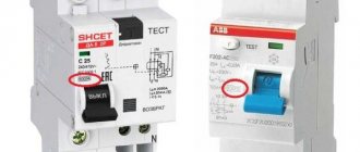
ASU 1M and ARU 3 are designed to replace ASU 1 panels and are distinguished by the use of automatic circuit breakers and switches with differential protection (RCD) instead of fuses. Due to this, the layout, dimensions and weight of the panels have been reduced.
Input panel on the pole
So what do we have initially?
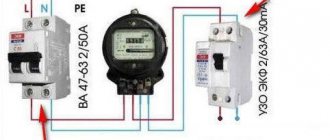
Local electricians installed a plastic box on a pole, which is better called a single-phase input switchgear (IDU) or metering panel, in which they mounted an AMS b1b-sa2sc meter and two machines - C63 before the meter, and C50 after it. Input cable – two-core, stranded aluminum with a cross-section of 16 mm2:
VRU. Aluminum cable entry on pole
An isolated overhead line (IOL) comes from a transformer, which is located more than a kilometer away. There is an assumption that the short-circuit current in the section will be relatively low. I wrote on my blog what this means and what conclusions can be drawn.
Closer photo of the internal structure of the shield:
Shield on a pole with input machines and a counter
Judging by the rating of the input machine, the allocated power is more than 13 kW, which is very good for rural areas. Next, the connection is made with rigid aluminum conductors with a cross-section of 10 mm2, and a 2x1.5 SHVVP wire with a length of more than 15 m is temporarily screwed in, which goes to the house under construction.
With such machines at the input, taking into account the fact that all electrical wiring will be done “from scratch,” it must be done with high quality, on a budget and safely. It is important that the scheme must take into account all the nuances that may emerge in the future, so as not to be remade later.
Structural electrical diagram of the site
First you need to decide what and where it will be:
In the ASU, electricity is distributed to three consumers -
- per home (main consumption), maximum power consumption - 7.5 kW, distance to the home distribution board (distribution board) - 15 m,
- to the summer kitchen (later there will be living quarters for guests) - 2.5 kW, distance to the control panel of the summer kitchen - 20 m,
- for outbuildings (workshop, shower, toilet), max. power – 2.5 kW, distance to the summer kitchen control panel – 20 m.
Block diagram of electrical equipment
All capacities are given taking into account a utilization factor of 0.7. This means that, theoretically, consumers can have the following maximum power:
- house – 10.7 kW,
- summer kitchen – 3.5 kW,
- outbuilding - 3.5 kW.
That is, up to 70% of all electrical appliances of each ASU consumer can operate for a long time at the same time. If the percentage (utilization rate) is higher - for example, relatives and guests have arrived, and a large feast is planned - then the time of simultaneous use of each of the consumers is limited to several minutes. After this, the corresponding AB can be “knocked out”.
Scheme of the ASU (input electrical panel)
Obviously, the ASU will have one input circuit breaker (AB), which is already installed, and three AVs, through which power is supplied to 3 consumers.
We select the cable cross-section and AB rating for
the house .
Now the AB is installed at 50 A, it will have to be removed. This relates to safety and costs - for 50A you need to install a thicker cable, this does not make sense. For a power consumption of 7.5 kW, the current is 7500/220 = 34 A. The cross-section of the copper core of the cable going to the house is chosen to be 6 mm2 . We select a machine with a rated current of 32 A (its time-current characteristic is such that at a current of 36 A it will turn off no earlier than after 1 hour)
For a summer kitchen and outbuildings (power 2.5 kW) you need cables with a core cross-section of 2.5 mm2 , protected by 16 A .
Next we solve the issue with grounding. It turned out to be not so simple. Two grounding systems suggest themselves:
TT – with a circuit (grounding electrode) not electrically connected to the PEN conductor or neutral coming from the street. The advantage of the system is that it is independent of the state of the street electrical network. There is no need to redo anything or connect anything additional. But the minus lies there too - if a voltage appears at the incoming neutral that is very different from the ground potential, it can do a lot of business. In addition, I recommend installing an SPD, because the Black Sea coast of the Caucasus, according to the map given in the PUE, is the most dangerous in terms of thunderstorm activity. And with a TT system, lightning protection will be cumbersome or ineffective.
TN-CS – grounding system with re-grounding and separation of the PEN conductor into the neutral wire (bus) N and protective PE. It takes a long time to explain, but such a system involves re-grounding, installing a main grounding bus (main grounding bus) and separating the PEN conductor BEFORE THE COUNTER. Otherwise, if the grounding is connected after the meter, it will be incorrect and unsafe. This is aggravated by the fact that the input is not a two-pole, but a single-pole AB.
You can read in detail, for example here – https://we.cs-cs.net/blog/506.html and https://cs-cs.net/vru-vvod-zazeml and https://zen.yandex.ru /media/yury_kharechko/kak-pravilno-vypolnit-zascitnye-provodniki-v-sistemah-tns-tncs-i-tt-5f9346b7a81c50318e18ec3e
Therefore, it was decided to install a protective grounding bus PE (GZSh) to the meter distribution block on a DIN rail RBDp-35 with a width of 43 mm. It has a central conductor, which passes through it through stripping the insulation, and can have a cross-section of up to 25 mm2, and 4 smaller wires - up to 6 mm2.
This block will play the role of a main shield, it will receive a PEN conductor from the street and a protective conductor from the grounding device (circuit) with a cross-section of 10 mm2. The protective conductor PE and the neutral conductor N (through the meter) will go from the GZSh (PE bus) to consumers.
I hope that the RBD-p with the PE bus will not be sealed (like the introductory AB). After all, the contacts need to be stretched, and it may be necessary to replace or add a cable. But if, nevertheless, the sealing of the RBDp-35 pass-through block is required by the energy supervision authorities, you will have to make a separate PE bus, which does not need sealing. And connect the protective wires of consumers to it. I just don’t know where to mount it in this cramped ASU. Perhaps on the bottom or side wall.
The RBD 80A distribution block with a width of 29 mm is used as bus N. You can connect 3 wires with a cross-section from 1 to 16 mm2 and 4 wires with a cross-section from 1 to 10 mm2. The neutral wire N comes to it from the meter output, and wires 6 and 2.5 mm2 go to consumers.
It is possible to form an N bus before the meter, and power the meter with one wire, but this connection often raises unnecessary questions from the relevant authorities. Moreover, the instructions for this AMS b1b-sa2sc meter do not contain such a diagram. Moreover, the meter is already connected, and there is no point in redoing its connection diagram.
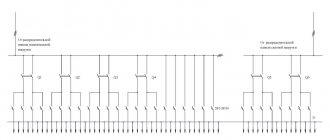
As a result, the diagram (more precisely, the location and connection of elements) of the ASU will be like this:
Electrical diagram of the incoming electrical panel
The PEN wire split will look like this (shown to explain the design of the RBDp 35):
Separation using pass-through block RBDp 35
The difference from what is in the photo is that after RBDp 35 we will actually have wire N, which goes through the meter to bus N.
Let me remind you that the layout and arrangement of the ASU elements is dictated not only by technical requirements, but also by the existing connection and arrangement of the elements, as well as by the dimensions of the panel.
A couple more questions regarding the ASU.
SPD , as I said, it is advisable to install it. But where to do this? Since there is no space in the panel, and it is dangerous to install the SPD in such a tight space, it is necessary (if such a decision is made) to install a separate box for the SPD. For connection: if it is possible to resolve the issues with sealing (i.e., either sealing is not needed at all, or they will be sealed without problems), take the phase after the incoming 63 A AB, put it in a box, and then connect it through a 50 A circuit breaker to the phase terminal of the SPD . Connect the ground terminal of the SPD to the PE bus. To connect, you will need 2 wires with a cross-section of 6 mm2 and a length of no more than 0.5 m, an SPD of class 1 is needed (another designation is B-class). Install class 2 surge protection devices in the control panel of the house, kitchen and outbuildings. Thus, the negative consequences of lightning strikes (and they happen very often in these places) will be significantly reduced.
Ground electrode. Here is what Nikita writes: “Tell me about grounding, will one metal corner driven into the ground or a round pin be enough? I watched them do this, they measure it with instruments, everything is fine. Some people simply make an outline from several pins and corners. And how deep should I drive it? The depth is motivated by the level of soil freezing, for us it is at “0” meters! Well, it’s not far from the waters here, they always stand a meter away. Let's say I drove 2 corners into the ground, welded a plate to them and secured it to a power pole, welded a bolt and nut onto it, take a single-core wire, screw it to the welded bolt with a nut. And about the depth of driving, if I have the South and the soil does not freeze, the water depth is always no more than one meter, then what depth should I dig a trench, also 0.5 meters? And to what depth should they be driven from the trench depth level? Can the welding areas be coated with bitumen mastic?”
Everything is correct. Place the ground electrode near the pole, weld it from 2 corners, remove the plate or corner with a bolt. The trench can be not so deep, 0.2 m is enough. The length of the corners is 2 m, if the ground is not rocky and it is possible to hammer in this length. If less than 2 m, 3 corners are better, at a distance of at least 1.5 m from each other. Treat welding areas to prevent oxidation.
Check the grounding for quality (it is better to do this regularly). If there are no devices, the normal home test option is to connect a 60...100 W light bulb to phase and ground (instead of zero). It should burn no worse than from phase and zero. That is, if the voltage on the light bulb does not differ much from the normal operating mode (the difference is a few volts), then the grounding is of good quality.
CS-CS.Net: Laboratory of the Electroshaman
ASU (panel on a pole) for a country house or cottage
In general, everyone knows HOW I HATE COLLECTING LIES (it’s already happened here). For those who don't know, here's a video:
Why do I hate them so much? That's why:
- You are faced with a terribly stupid bureaucratic machine of electrical networks that doesn’t give a damn about all modern standards, doesn’t give a damn about modern competent modules, beautiful machines, power buses, distribution blocks, or the IP protection level of street panels. They only care about one thing: that they don’t steal. Because of this, they force you to do such CRAP that you want to bang your head against the wall and cry. Or go and beat them all with wood.
- They begin to extract money from you and put a spoke in your wheels to get it out. For example, for some networks, assembling a panel in an IEC housing from two ABB SH200L circuit breakers and a meter and connecting it costs 80 thousand for the work (!!). You get shit for this. If you make a shield more competently, but your own, then they start to find fault with every little thing.
- They force you to install two machines: one before the meter, the other after the meter. This is motivated by the fact that in the event of a short circuit, the current will first reach the machine, which is after the meter, it will turn off and save the meter. They don’t even want to listen to the fact that in a series circuit (TP - highway - Automata - Meter) the current is always the same.
- It's idiotic to install SIP in these same ASUs. Nobody gives a damn about the IP protection level. SIP (which is resistant to solar radiation, but flammable), is put into gray plastic pipes (which are not resistant to sunlight) and, using a piece of gray corrugation (which is also not resistant to sunlight), is inserted into our shield. Sometimes without cable glands at all. The gray corrugation wears out over time. But the clause of the PUE “cables running at a height lower than 1.5 meters must have mechanical protection”, which most likely does not apply to overhead lines (which include self-supporting insulated wires), is observed.
- Electrical work is not enough. Sometimes it's just six wires. But mechanics are terrible. And we drank, and drilled, and worked with hydraulic presses. But you can’t get a lot of money for it: after all, outwardly the ASU for the user is just an iron box with machines and a counter, right?
- A LOT OF PAPER! If you don’t know, my papers are divided into “necessary” and “unnecessary”. And the ones that I don’t need, I HATE and they make me naturally sick, throw me into a panic and I start yelling, like in the video. For me, papers are very strongly connected with people, and it is in papers that I very much see people’s indifference... In short, I don’t know how to explain this, but I can look at a form/form/letter/standards and FEEL that in one case people thought about others when they did it, but otherwise they didn’t give a damn, and it’s a piece of paper for the sake of a piece of paper. And in the latter case, I feel righteous anger and I don’t want to see such papers. Unfortunately, VRUs are most often dull carbon papers. The same TUs that are sometimes sent to me are written in such a way that they can be interpreted as one pleases. For example, they write about a “power limiting device,” and there are three options: a meter with a power limit, a separate power limiter, or even an input machine for the desired rating. As a result, a simple ASU like “box, counter, machine” turns into papers and correspondence about nothing. At the same time, it is impossible to find someone who is responsible for this and find out everything for sure. Nobody is responsible for anything.
So here's my story. I once made a switchboard diagram for a customer last year. Then he appeared and asked me to make him an ASU (panel with a meter) for a pole, because he had been allocated as many as 80 amperes (quite officially). I skeptically sent him to the post about the previous Verkhovna Rada, and also bombarded him with questions. Something like this:
- The exact diameter of each wire-cable that will enter and exit our panel. This is necessary in order to calculate and install PG seals there and maintain the tightness of the shield. You need to take into account everything, everything, even how the SIP will be inserted there: each core separately (and then you need 4 small seals) or in this idiotic corrugation entirely (then you need to know the corrugation).
- What kind of meter should I install? It turned out that you can plug in a direct connection meter for 10-100A, the most common Mercury.
- What denomination of the introductory machine should be set and whether it can be set ONCE (there will be an explanation about two machines after the list). Which of them need to be filled, and which ones don’t.
- Which line is it and is it possible to make a TN-CS system there and separate the PEN. Know whether this node will need to be sealed and whether local power networks will separate PEN normally - before the meter, and not after (this will be discussed at the end of the post).
Only after this can you start counting something. Therefore, those who write to me: “Make a lie” and send this idiotic piece of paper with the name “TU”, in which NOTHING is written, go through the forest... uh... read this post. I will link to it and ask: “Are you ready for this? Are you sure you're ready?"
About two machine guns . Here (post about trays in the country) I have already encountered this insanity. For some reason, the electrical networks are forced to install two input machines. One is before the meter (and usually it is sealed), and the second is after the meter. Initially, this insanity was explained by the fact that during a short circuit the current would not have time to reach the meter and the meter would be saved. But this is complete nonsense and insanity! That’s why, in order for it all to be accepted and sealed, I need to show humility and nod in agreement while listening to outright bullshit?
What's wrong with two machine guns and why am I yelling and getting angry about it? And the fact that the machines are not always ordinary, which cost 2-3 thousand. In some cases, we need to supply circuit breakers with a higher breaking capacity (for example, the S800 - I mentioned it in the post about the ABB module) or even special selective S 750 DR . So what should I do? Buy two machines for 18 thousand each? Has anyone checked whether two S750 DRs will work in series with each other? And what’s worst is that the second machine after the meter is not required to be sealed. That is, later I can throw it away - there are no fillings. And why should I install it right away?
Peter_Witt from the community is trying to reason with me and says that all these two machines are needed so that the meter, if it has a PLC modem, does not fall out of the network, because it works as a repeater. That is, when people leave, they will turn off one of the machines, and the meter will be visible in the ASKUE. But this, IMHO, is also nonsense. When shorted, it will knock out two machines in a chain. This time. Many people, out of fear, will turn off both machines when leaving - just to be sure to turn them off. Therefore, this explanation did not satisfy me and did not add understanding.
How could it be done? Place a switch before the meter, as has always been the case in all large ASUs: input goes to the switch, then to the metering unit, and then to the machines. This option is best for us: we don’t touch anything before the meter, but we have something that turns off the power completely, but does not turn off during a short circuit after the meter. If you believe the nonsense about PLC modem repeaters, then this would be the ideal option for them! The switch will not turn off during a short circuit, and the meter will not fall out of the network! And after the counter - once an introductory machine under the seal. And if we need to change the machine or increase the allocated power, then we turn off the switch and do what is necessary.
Another option is to place one input machine of the required type and rating (“Good!” ©) before the meter under a seal. After the meter, pull out the power supply to the terminals on the DIN rail, so that you can not touch the seals on the meter, but also connect after it (via these terminals) what you want: a temporary shed, a cable to the house, or something else.
About approvals. It’s even worse with them, because there is NO ONE person with whom you will work and with whom you can talk and discuss your ideas! There is a bureaucracy and a bunch of different people who don’t know anything (“Are there any complaints about buttons?”©). And there are those TUs that are very vague. It simply states that it is necessary to ensure power metering and limitation. How? How exactly? Not indicated. And it turns out that the “switch - meter - automatic” circuit fits the specifications, and the “automatic - meter - automatic” circuit also fits. The specifications (and the single line on paper) are accepted by the company itself, and the fillings are performed by local teams who do everything in their own way.
That's how many questions, twists and turns and crap are put into these iron boxes. Therefore, I work with them in a stupid mood and feel that I am doing crap, like from a book about partisans (“Unforgettable Days,” it seems): “Put in a bunch of crap, but make everything shine! The Germans love order! Therefore, if you want to order an ASU from me, then kick the power grid and find out everything down to EVERY THING. TO EVERY SCREW - and with that to me. And with TU - nah!
In our community, user Syo wrote a large post with a bunch of standards - TN-CS, PEN separation, standards , which can help defend the TN-CS system and force electric network installers NOT to put PEN into the meter and not even seal N/PE buses. Honor and praise be to him!
And that’s why I turned away for a long time from the customer’s request to make him this ASU. And then he and I sat down with me and I warned him about what he might encounter when he installed this ASU. I remember very well how the installers wanted money on the last cabinet. There had to be a TT system because the input is air. Well, we installed a four-pole input circuit breaker. The locals arrived and said: “Nope, but the zero needs to go through the meter.” The customer told them: “So, pass it through the meter, and use three poles from the machine,” and they go ahead: “Nope, in that case the machine should only be three-pole.” A crazy cuckoo with a tuft on its ear! Why is this happening?!
A piece of the customer at a consultation before developing an ASU
In short, the end result was great insanity. We do TN-CS. It was easily agreed upon. The 80A automatic was easily agreed upon (I don’t care at all). But if there was only one machine gun, no, they don’t care. Let me remind you: this machine is NOT sealable. So I can twist it later. And what is the point in it?! THE FUCK?! Oh, how much hellish hatred I have for them!
Let's start collecting! I easily screwed everything onto the cabinet mounting panel from DKC (the same ST ) in half an hour. I marked with a metal scribe along a ruler - this time I wanted the markings to leave a beautiful grid of lines and stripes along which I made the holes.
We begin to assemble our ASU - we secured everything on the mounting panel
Oh yes. I completely forgot! They already wrote to me in a video on YouTube that in the regions they seal everything with stickers. It's awesome because you can seal anything with them. Even the screws on some terminals can be sealed. And the terminals may be suitable if we also install an SPD here: SPDs must be installed before the meter in order to protect it. By the way, this point also needs to be clarified with the senile energy sales people. Otherwise, it turns out later that lightning may burn the meter, as long as they don’t steal it.
We connected the meter and the input machine
We still use stupid boxes for filling. I'm not against them, but they are unpleasant because they are flimsy. The same S800 is already wobbly there and sometimes it seemed to me that the plastic DIN rail in the box would crack. But the S750 DR will not fit into this box at all, because it protrudes more from the center of the DIN rail than the S800. But, still, compared to the fact that you need to install a second machine, the boxes are a trifle!
Go ahead. I switched the counter to PuGV for 16 squares. The counter needs zero ONLY for its operation. Therefore, it can be connected with a wire of at least 0.75 square meters. For massiveness and beauty, I took a wire of 6 squares. All tips are crimped twice in length so that they fit deeply into the meter.
Phase wires to the meter and zero wire
Mercury's clamps are evil! The fact is that everywhere the clamp, when you unscrew it, goes down, and therefore all that remains is to thread the wire there and tighten it. In Mercury, everything is through the ASS: the screws are simply loosened, and nothing happens. I fucking can’t help but speak in rude and vulgar language. It's like sex. If it’s in the front (from normal manufacturers), then everything works out there on its own. But if it’s through the ASS, then, damn, of course, it needs to be developed in advance! In the case of mercury, slip in some thin screwdriver, push these contacts apart and slip in the wire. Some kind of fucked up guy!
Well, its lid is such that you can’t cut it out normally. You can cut through the edges and then you have to break them out. And breaking them off leaves nasty hangnails. Why the hell do you do that?
Terrible meter cover
In the end, except for the counter and the machines, the rest didn’t bother me and went together quickly and easily. It turned out like this. We connect PEN to the N/PE separation unit on two BRU125 blocks. Next to the same blocks there are three more in order to connect the cable to the panel of the house at this point. It will be 25 squares of aluminum, so the BRU blocks are turned upside down so that the large hole on them is just on the side of the cable into the house. To the left of all these blocks there are machines for street lights, gates and a couple of sockets.
The entire installation of the ASU has been completed. Hooray!
Since we turned the BRU blocks upside down and since they only have one large hole, I supplied power to them after the machine with two 10 square wires. It turned out quite technical and interesting.
Connecting BRU125 units to the S800 machine with the reverse side
The rest of the shield was made with the help of combs and two-pole machines, so as not to fool around with the zero busbars!
Part of the supply of conventional lines
And then there were two days of swearing. Let me explain again. I love making things when people NEED them. Therefore, I turn down those who (figuratively) throw all sorts of bullshit single-rulers in my face with the look: “Well, calculate it, tell me how much it will cost,” or when I understand that it could have been done differently, simpler and more convenient. In this case, I force myself and hate what I do.
So I flew with PG42 under the 32nd corrugation. Which is not resistant to ultraviolet radiation, but in which it is necessary (blah) to install a SIP in the shield! Who even came up with this idea? And it turns out that there, from the pole, all the water will flow into the plastic pipe through the seams of the connections, then flow into this corrugation, and then into my shield. And in five years this corrugation will fall apart from the action of the sun. Holy shit!
And because of this crap, I hated the hole I had to make! It so happened that I didn’t have the right crown, the right drill, nothing. There was no time to run out and buy it, but it had to be done by the next weekend. So I was doing, uh... fisting, for fuck's sake! Moreover, I know myself: if I understood that this was really NECESSARY, then I wouldn’t worry and the work would go smoothly.
Cable gland PG42 and HOLE!
Let's break it all down...
Way to cut an awfully big hole!
And we take our favorite weapon. Round file. AND JERK OFF!! Until I'm blue in the face.
The file is our everything!
As a result, immediately after this shield (I added my own money from it) I ordered myself a hydraulic press KVT PGPO-60A! It has already arrived and as soon as I buy a simple metal shield for the dough, I will tell you about it in posts.
PG cable glands are in place
After this hell, all that was left was to screw the mounting kit onto the pole. for now I take them from IEK. They are good and comfortable. I came up with the idea in the future to try to take two such sets for a larger box in order to attach it in pairs for reliability.
We attach the pole mounting kit from the IEC to the panel body
For the kit, I drilled new holes, and I closed the holes that were not needed (but were from the factory) with rubber gaskets (I got them from Leroy): I laid them on both sides and secured them with M6 screws and washers.
Insert rubber gaskets into old holes
That's all! Then we throw all sorts of fasteners and other accessories into the shield and everything is ready!
The ASU is completely ready and packed
I also liked the beautiful PE wiring and this corner of the shield. And I decided to share a beautiful photo!
Beautiful ground wire for the panel door
After the customer took it all, something worried me. I didn’t sleep at night and was worried about how this ASU would be connected and hung there. And so the customer sent photos!
The ASU was hung on a pole
All the peppers were installed from energy sales. The customer was not at the site at that moment, and the people were only doing installation. Here you can clearly see this BASTARD insanity with non-light-resistant gray pipes and corrugation! what the fuck are the IP protection levels? And how will a plastic pipe provide mechanical protection to a SIP? You can break it once or twice!
Idiot connection of SIP to ASU in corrugation
And then I saw how my ASU was connected and FUCKED. Both Alexiy and Peter_Witt proved to me that the “Shops weren’t stolen” feature is a hundred times more important than a normal PEN connection to the GZSH in order to separate it. I radically disagree with them. First, we split the PEN at the input, and then we do with it what we want and how we want. It has always been this way, and this is how I was taught.
What did these nits do here? Without hesitation, they dragged the PEN into the counter. From there it goes with a frail 6-square wire to the PEN separation unit. How can I unsee this?! Do you know how they explain this? And so that they don’t steal! They say, you can turn off the zero and take it from the PE and work around the counter. But damn! So we have zero and PE connected together at the GZSh! And so along the entire line there is repeated grounding, and there, at least tear off zero, at least don’t tear off - it doesn’t matter! This was true for old single-phase networks, yes. But now it turns out that for the sake of an idiotic whim, the PEN division has been completely violated, which can be dangerous!
Right now there will be another question: “So it was necessary to simply make it possible to seal the N/PE node.” Damn! They specifically asked, showing them a wiring diagram on a piece of paper: “No, nothing needs to be sealed.”
The idiots connected the ASU and ruined it
I'm terrified of the electrical grid. For example, it is often easier for them (“so as not to steal”) to force us to use the TT grounding system, which is more dangerous than TN-CS - in the TT system, the zero hangs by itself, and anything can fly along it, up to the phase. In the TN-CS system, this same “zero” is always re-grounded, so even if some voltage appears on it, the short circuit protection will work.
Now the customer’s shield is connected, but not yet sealed - there is a chance to fix everything. And he and I argue with the networks and come up with a solution: either plant a nut on the SIP, from which we drag a thick wire to the N/PE buses, or force them to screw the SIP zero into the N bus, where it should be. It would be better to screw it into place, because then this fat SIP will not spoil the appearance of the ASU inside, passing over the wires near the cross-phase blocks.
These are the pies. It turns out that I am not a performer, a master - and I cannot work like a robot. I think through all decisions and always choose the more reliable option. And I don't do bullshit. Therefore, I can do VRU - but it will not cost 5-10 thousand (because a lot of nerves are put into it), and I will do them ONLY on the condition that all, all, all issues are resolved in advance. Including about two machines, and about sealing the PEN separation unit.
Home electrical panel
According to Nikita, the control panel in the house will contain the following consumers and groups:
1) refrigerator up to 500 W / 2.27 A / 1.5 mm cable / automatic C6 2) Electric stove 2.5 kW + hood 0.5 kW + electrical appliance 1 kW = 4 kW / 18.18 A / 2.5 mm / C16 3) washing machine 2.5kW/11.36A/2.5mm/C10 4) water heater 50-80 l 2kW/9.09A/2.5mm/C10 5) Bedroom: heater 1.5kW+0.5 gadgets=2kW/9.09A /2.5mm/C10 6) children's room: heater 1.5kW+0.5 gadgets=2kW/9.09A/2.5mm/C10 7) bathroom: hairdryer 1.5kW+heater 1kW=2.5kW/11.36A /2.5mm/C10 living room: gadgets 1kW+electrical appliance up to 1.5kW=2.5kW/11.36A/2.5mm/C10 9) light around the house up to 5 amperes/1.5mm/C6 10) Reserve oven until I’m not betting, but we’re counting on it right away. 3kW/13.63A
The total load is obtained if everything is turned on at once: 22.5 kW and 100 Amperes.
My answer, some aspects of electrical panel building:
There are no powerful pumps or sawmills in the house. In addition, I am sure that in rural areas the short-circuit current is small. Therefore, I insist on installing circuit breakers with a tripping characteristic of type B. Read why in private homes it is better to install circuit breakers with a characteristic B rather than a C. In short, circuit breakers with a time-current characteristic “B” work much more reliably where there is a large distance to the transformer substations and worn-out electrical networks. As a result, an electrical installation with “B” will be safer than with “C”.
The maximum current will not reach 100 A, since it will be limited to AB 32 A. As I said, this is quite enough for an ordinary house, since everything will never turn on at once. Therefore, all cables with a cross-section of 2.5 mm2 can be protected by AB at 16 A - such a machine will perfectly protect the cable during overload and short circuit, and there is no need to limit power by group.
Installing an RCD is more preferable than a difavtomat, since it allows you to create more flexible systems. For example, it is very difficult to find a differential automatic machine with a time-current characteristic “B”. And it is much more difficult to determine the reason for the operation of the differential circuit breaker than in the case of using the RCD + AB combination.
If possible, it is better to buy electromechanical RCDs (more reliable than electronic ones) and with the “A” type of differential current (if there are a lot of electronics in the house, “A” provides greater safety than the cheaper “AC” type).
There is no need to install an RCD for lighting. On the refrigerator too - it will have to be hung on a separate differential circuit breaker or RCD, because if there are other problems on this RCD, the refrigerator will be left without power. Therefore, if the new refrigerator is powered through a separate AV, and there are no open grounded objects nearby, it is better not to install an RCD.
At the entrance to the home distribution board, you need to install an introductory 2p automatic machine, despite the fact that there is an automatic machine for the house in the main switchboard. This is necessary for convenience - it is convenient to run the wires, and it is convenient, if necessary, to instantly turn off the power to the entire house. After all, you need to run to the pole, and the main switchboard may be locked (this is the stupid requirement of local electricians).
A voltage relay is another component to protect household consumers. If the voltage goes outside the limits (for example, 175...245 V), the house will lose power. I recommend installing voltage relays in several articles on the blog. Plus voltage relays - almost all of them show the current voltage value, and some (this is especially convenient) - current consumption and power.
The rated operating current of the RCD and voltage relay in this case must be no less than the rated current of the input circuit breaker - 32 A. Better - more.
As a result, the scheme will be like this:
Home electrical panel diagram with voltage relay and RCD
Loads:
- L1 – Electric stove, kitchen sockets,
- L2 – Washing machine,
- L3 – Water heater,
- L4 – Bedroom,
- L5 – Children’s room,
- L6 – Bathroom,
- L7 – Living room,
- L8 – Oven,
- L9 – Refrigerator,
- L10 – Home lighting.
Description of the shield device.
The PE, L and N wires come from the ASU via a three-core cable. The PE protective grounding wire comes to the PE bus, to which the protective conductors of all consumers are connected. All new shields usually already have this tire. If the shield is metal, it is also grounded.
The phase and neutral L and N pass through a two-pole switch on the voltage relay (I wrote about this above). After the voltage relay, the phase and neutral are supplied to the cross-module X0, which is needed exclusively for convenient, understandable and high-quality installation. The cross-module contains 2 buses, each of which must contain at least 5 screw terminals. In order not to clutter the diagram with wires, the connection is indicated by one wire; in fact, the connection will be separate wires from X0 to QF1, QF2, QF3, QF12+QF13.
You can do without a cross-module using jumpers. The main thing is that a maximum of 2 wires should be pulled into one terminal, and always of the same cross-section.
RCD QF1 “works” in two groups – L1 and L2. Three groups are connected to the RCDs QF2 and QF3. For ease of installation, I suggest using local neutral buses, shown in the upper right corner of the diagram.
Main technical parameters of the ASU:
| Parameter name | Parameter value | ||
| AC | DC | ||
| Rated voltage of the main circuit, V: | 24; 220; 380; 660 | 24; 48; 110; 220; 440 | |
| Rated voltage of the auxiliary circuit, V: | 24; 42; 60; 110; 220; 380 | 5; 12; 15; 24; 48; 60; 110; 220; 440 | |
| Rated currents of busbars, A | open shield | no more than 4000 | |
| protected shield, cabinet | no more than 4000 | ||
| multi-box shield | no more than 1000 | ||
| Rated short circuit shock current, kA: | for open panels | 16; 25; 40; 50; 70; 100 | |
| for protected panels | 6,3; 10; 16; 25; 50; 70; 100 | ||
| Limit values of permissible short-circuit shock current, kA | for open panels | 100 | |
| for protected panels | 100 | ||