High-quality implementation of certain technological processes in the modern world is ensured by high-precision and expensive equipment. The operation of which directly depends on the quality of the supplied electricity and the condition of the power supply lines. Unfortunately, not all domestic networks are able to provide a safe operating mode for them, which creates a threat of breakdown. To prevent this, special protective devices are used - phase control relays (PKF).
They allow you to disconnect the load in case of any malfunction in the power supply network. Anything that may pose a threat to the equipment and affects the performance of its operation or the technological process is perceived as a signal to immediately de-energize and the control relay moves the switching elements to the off position.
What is it for?
A phase and voltage control relay is a device that is necessary when connecting equipment to a system with three phases, as well as in situations where it is important to maintain correct alternation.
In practice, the product is used when equipment is frequently transferred, when changing the phasing may cause damage or incorrect operation.
A striking example is a screw-type compressor, the incorrect connection of which and switching on for more than five seconds leads to breakdown of an expensive product.
The phase and voltage monitoring relay allows you to identify the following problems:
- Break of any phase;
- Increase or decrease in voltage above (below) a given level;
- Phasing violation (phase connection order);
- Break of “zero”;
- Asymmetry of I and U (here we are talking about phase imbalance, when the angle between the vectors is significantly more or less than 120 degrees).
The schematic diagram of the device is shown below.
Some relays provide the ability to change the settings for the upper and lower limits U, as well as T (time) of operation.
As a rule, the output contact group of the relay is “dry”. In this case, there are two options available - normally closed and open. Some models have elements that operate on the induction principle.
Bottom line
At any industrial enterprise there are hundreds and thousands of three-phase asynchronous motors. No matter how modern and reliable the motor is, if during operation one of the phases feeding it disappears, it will burn out. The cost of the largest and most powerful engines is comparable to the price of a good car. A control relay costs much less than a motor. But it will definitely save him in the event of a phase failure. This explains the economic feasibility of installing RKF for engine protection.
Voltage quality is important not only for asynchronous machines. When there is a short circuit in the line, the voltage in one of the phases drops to almost zero. This mode of operation is unacceptable. RKF will notice a critical voltage imbalance and turn off the line. Thus, all consumers will be protected from abnormal operating conditions and subsequent losses.
With this in mind, the RKF is far from the least important protective device. It has not lost any relevance since Soviet times. On the contrary, with the development and complexity of equipment, the relay is only becoming more in demand, because it allows you to protect expensive electrical machines from breakdown.
Design and principle of operation
Despite the variety of voltage phase control relays, the design features are almost unchanged. The device is based on microprocessors with an embedded program and the ability to customize. This design ensures reliable operation and low maintenance.
The design of the product also includes a circuit that calculates the order of the arrangement (sequence) of phases, and also monitors the compliance of the current situation with the program that is embedded in the relay.
On the simplest models, three phases and a neutral conductor are connected to the input, and a relay with a changing contact is provided at the output terminals.
Voltage to the internal circuit is usually supplied from the first phase (L1). For clarity, a pair or more indicators are installed (much depends on the product model) and the manufacturer.
More expensive relays have a regulator that allows you to change the setting over time (see photo above). Thanks to this option, you can increase or decrease the relay response time when executing a specific program.
In addition, many devices have a circuit that responds to a decrease or increase in voltage.
The operation of the U phase control relay is based on the separation of negative sequence harmonics (from 2 and above). In this case, only harmonics that are multiples of “two” are used, that is, “fourth”, “sixth”, “eighth” and other harmonic components. They appear in the event of a break in any of the supply phases.
To isolate such U, special filters (also negative sequence) are used, the role of which is played by analog-type filters. They include active and reactive units (resistors and capacitors, respectively).
General information about the device
The functionality of electrical devices of this type is much broader than just protection against overheating and short circuit.
In practice, the effective properties of overloaded phase selection relays have been noted, which ultimately provide comprehensive protection.
One of the many options for design solutions in the production of phase relays. However, despite the variety of cases and circuit configurations, the functionality of the devices is the same
Thanks to phase tracking devices, the following benefits are achieved:
- increasing engine service life;
- reduction of costly repairs or engine replacement;
- reduction of downtime due to engine defects;
- reducing the risk of electric shock.
In addition, the device provides reliable protection against fire and short-circuit of the motor windings.
Types
The most popular types of relays designed for phase control include EL models of the following series - 11, 12, 13, 11MT and 12MT.
It is important to take into account that the scope of application of the product depends on their types of voltage phase control relays (EL):
- 11 and 11 MT - protection of power supplies, participation in the automatic transfer system, power supply of converters and generator sets.
- 12 and 12MT - to protect cranes with a power not exceeding 100 kW.
- 13 - used when connecting electric motors of a reversible type with a power of up to 75 kW.
The devices are fixed on a special DIN rail or only with screws (depending on the situation).
Characteristics
Modern phase control relays are selected taking into account the following characteristics:
- VOLTAGE. Operating U directly depends on the equipment specification. For example, EL Series 11 can operate at voltages from 100 to 415 V (including 110 V, 220 V, 380 V and 400 V). As for EL 13, they operate on voltages of 220 and 380 V.
- OPERATION LIMIT. This parameter also depends on the type of relay and the current situation. Thus, with a symmetrical decrease in voltage, EL series 11, 12 and 13 devices have a minimum limit of 0.7; 0.5 and 0.5 Ufn respectively. In the event of a break in one or more phases, all relays will operate. If the alternation is disrupted, then models EL11 and 12 recognize the problem and close the contact group, but EL13 does not.
- DELAY TIME. This indicator reflects how much the response of the voltage phase control relay is delayed when the required setting is reached (the specified threshold value). For models EL11 and 12 this figure is from 0.1 to 10 seconds (depending on the adjustment), and for EL13 - up to 0.15 seconds.
- WORKING TEMPERATURE. As in the cases discussed above, the situation here depends on the type of relay. EL types 11 and 12 operate from 40 degrees below zero to 40 degrees above zero. As for EL13, these relays have a smaller range - from -10 to +45 degrees Celsius.
- Storage temperature - from -60 to +50 degrees Celsius.
- Product weight - 300 grams (EL 11 and 13) and 250 grams (EL 12).
Types of RKF
Different RKF models have different technical characteristics. Therefore, each of these devices belongs to one type or another.
According to the settings options, relays are divided into 2 categories:
- Adjustable. It is possible to set the required response setting for voltage and time (EL-11, EL-12, EL-13, EL-15).
- Unregulated. Only factory settings are supported. An example of such a device is E-511.
Relay EL-13E
Subtleties of choice
When choosing a voltage phase control relay, you need to focus on the technical parameters of the device that is connected to the circuit.
For example, consider a situation when you need to select a model for connecting an ATS.
The algorithm of actions is as follows:
- WE DETERMINE THE CONNECTION METHOD - with or without “zero”.
- WE DETERMINE THE PARAMETERS. For an ATS circuit, it is important that the device monitors the fact of phase failure and the phase sequence. In this case, the delay time should be in the range between 10 and 15 seconds. Control of oscillations U greater or less than the set point is required. To switch a relay with the 0th wire, visual inspection is required for each phase.
After analyzing the requirements considered, preference can be given to EL11E.
In addition, when choosing, you need to take into account the modification of the relay. For example, domestically produced devices are designated as EL.
As for foreign products, their markings are somewhat different. For example, RANA B380 A A 3 C. Here “RANA” is the name of the series, B380 is the voltage 380V. The next two letters A are regulation using a potentiometer and the type of installation (for DIN rail). The number “3” indicates the case size of 3.5 cm, and C is the last digit of the marking.
What is alternating current
Standard three-phase input:
In order to understand the need for 3 phases of power supply and corresponding protection on the lines, we will first analyze what specific current we are talking about. Unlike direct current, the movement of electrons in each alternating current line occurs in accordance with the sinusoidal field voltage. At the moment when it reaches its peak, the movement of particles is maximum in the channel towards the neutral or phase wire with the current zero index. The latter becomes like this during the period when the field power in it is equal to “0”. Then the force that moves the electrons of its sign changes polarity and continues to move particles with the opposite charge in the channel.
This periodic movement of electrons is the essence of the concept of alternating current. Its advantages compared to permanent:
- The line load is not constant, which means the energy transmission channels can be made physically thinner relative to those used during continuous movement of electrons.
- The possibility of economically transmitting current over long distances by raising its voltage with simple transformers at the beginning of the path and then reducing it to operating characteristics using the same devices located on the receiving side.
- The creation of a circular magnetic field is simplified, which makes it possible to simplify the design of electric motors.
- Obtaining two operating voltages in three-phase devices.
- With symmetrical characteristics on all three lines, the end consumer using them for their power supply does not need a separate neutral. The incoming alternating current is enough for him. Of course, with appropriate connection of lines and load.
Example of a 3-phase system without neutral - star connection:
Another way to connect three-phase equipment without a neutral (if in its design the load is connected in a delta connection). True, for the mentioned case, installation with the correct alternation of input phases is required.
Triangle connection of consumers and generating capacities:
One of the phases, together with the neutral, can be used to power a relatively weak consumer, which is what is done in residential premises. Usually, only one line out of three is installed for the entire apartment with a common zero.
Phase control relay EL-11E (380 V, 50 Hz), RKF, IEK
These phase control relay models are produced by, which has been on the market since 1992. The company is located in St. Petersburg.
The company's activities are based on the development and manufacture of industrial automation devices. During its existence, the company has managed to take a leading position in the manufacture of electronic devices on the Russian market. The number of goods produced exceeds 500 units.
The company's clients include such giants as Gazprom, Russian Railways, Aurora Concern, Lenenergo and others. The company's products are in high demand due to their quality and wide range of models.
Customers have at their disposal electronic time relays, voltage monitoring devices, maximum current relays, lighting control devices and much more.
Description and technical characteristics of relay EL-11E (380 Volt, 50 Hz)
The EL-11E relay has one normally closed, normally open and changeover contact.
The device is designed to control phases in a 3-phase network, operating at an alternating voltage of 380 Volts. In practice, it is used to control the presence of U and correct symmetry.
Phase control relay Schneider
The Schneider company is considered one of the best manufacturers of devices in the electrical power industry. The products of this company are actively used both at civilian sites and in large industrial organizations.
The advantages of the company's products include a flexible pricing policy, high quality and special conditions for customers.
The company produces circuit breakers, fuses, load switches and switchboard equipment.
In addition, the Schneider plant produces relays, switches, sockets, contactors and many other devices.
Popular models include relays:
- Control of 1-phase voltage (from 65 to 260 V and time delay from 0.1 to 10 s - RM17UBE
- 3-phase voltage control (208 to 480 V) - RM17TE
- 1-phase voltage control (160 to 280 V, 30 second delay) - EZ9C
- 3-phase voltage control (from 208 to 480 V) - RM17TT00 and others.
ABB phase monitoring relay
ABB has been operating since 1883, which is further confirmation of the reliability and relevance of the Swiss brand’s products.
Initially, the manufacturer produced generators and lighting devices, but in 1891 the production of electrical machines began.
At the present stage, the manufacturer’s offices operate in numerous countries around the world, and their number has exceeded 100.
The company produces and markets products for automation of production, generation and transmission of electricity, protection and automation of various facilities in the energy sector.
The most popular models include the following voltage control relays - CM-PVE, CM-MPS.21S, CM-MPS.41S, CM-PFS and others.
They all differ in voltage level, type of fastening, holding time and other parameters.
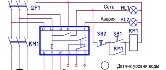
How to connect the device? Scheme
Let us immediately note that if a frequency converter is used in the equipment connection circuit, the installation of a voltage control relay is not required.
When connecting the product, it is important to follow the instructions supplied by the manufacturer. In most cases, the diagram is indicated directly on the product body, which simplifies installation and connection.
Connection to the product contacts at the input and output is carried out using wires, and they are secured using special clamps.
Wires of 2.5 “squares” or double wires of 1.5 “squares” are used as a conductor. When connecting, it is important to observe the correct rotation of the three phases.
The connection diagram can be different, both with and without a “zero” wire. The first option is usually found in private houses and apartments. In this case, the load is evenly connected to each phase. If there is a deviation from the norm, the relay is activated.
Diagram and video of connection EL-11M-15
Circuit design
Within reasonable limits, the RKF connection diagram depends on the developer’s imagination. The standard device has 3 inputs for connecting phases. They are usually located at the top of the device. At the bottom there is a terminal block with 4 pins - NO and NC relay contacts. Some actuator is connected to them. For example, a more powerful relay, contactor or magnetic starter. It is possible to connect the load directly, but you need to take into account the current it consumes.
Relay design elements
Old Soviet relays for monitoring open-circuit and phase rotation were fixed to the mounting location using 2 screws. Modern devices are equipped with DIN rail mounting. This approach simplifies the repair and development of electrical cabinets.
The second design feature of the phase control relay is screw terminal blocks for connecting wires. The vast majority of protection devices are equipped with such contacts.
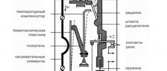
Adjustable controls
Regulators for setting the relay operating parameters are located on the front panel. This allows you to make changes without removing the device itself from the electrical panel. The regulators are made on the basis of trimming resistors. They do not stick out from the surface of the device. To rotate them, you must use any suitable screwdriver.
Some models of network imbalance protection relays are equipped with buttons and a display. In such devices, nothing needs to be rotated. However, it is somewhat more difficult to understand what is regulated and how. Especially without a user manual.
Electronic control device
Pin assignment markings
In terms of marking and designation of terminals, everything is the same as on any modern devices. The letters on the device body have the following designations:
- L1, L2, L3 - terminals for connecting 3 phases of the controlled network;
- NO/NC — output relay contacts;
- Umax is the maximum voltage threshold at which RKF will turn off the protected equipment;
- Umin - respectively, the minimum shutdown threshold;
- delay - the time after which the relay will operate.
Note! NC/NO (normal closed / normal open) - normally closed/open relay contacts. This marking is used on all modern equipment. The NC contacts are in a closed state and are short-circuited with a multimeter if voltage is not applied to the relay coil. As if it was just lying on the table. NO - opposite contacts. Without voltage they are in an open state.