How to solve the problem of high starting currents in asynchronous three-phase motors. How the star-delta circuit is implemented in practice. Restrictions on the use of different circuits for connecting windings of asynchronous motors.
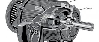
According to available statistics, about 95% of industrial equipment is driven by asynchronous electric motors, and their power is much greater than that of motors used in household appliances. A special feature of the operation of such motors is the increased starting current, which exceeds the rated current several times.
This is a necessary measure, since the motor shaft, being at rest, requires great effort in order to start rotating. And when it reaches operating speed, the force of inertia begins to work, and maintaining rotation at the same speed requires less energy, in our case electrical energy.
On the other hand, increased values of the starting current are not good, and from different points of view. Firstly, when such an electric motor is turned on, a jump occurs in the network: due to increased starting currents, a voltage drop occurs, which can cause damage to other electricity consumers. The most telling example is the blinking of a light bulb during operation of even a relatively low-power welding machine. We all know the consequences of power surges, and industrial equipment in this regard is just as vulnerable as household appliances.
But for the electric motor itself, increased starting currents cause faster engine wear. In addition, this leads to short-term overheating of the windings, which over time can result in insulator breakdown and short circuit. In other words, the engine will burn out sooner or later if nothing is done.
Many ways have been invented to solve this problem, but one of the easiest to implement is considered to be the use of a combined star-delta circuit, which allows you to use the operation of an electric motor with reduced starting currents during spin-up and another circuit design when the motor shaft speed reaches its nominal value.
What is the difference between star and delta winding connection diagrams?
In electrical engineering, both circuits are used very actively, and not only for connecting the windings of electric motors - if there is a load, it is often connected with a star or triangle. Take, for example, heating elements for industrial and household electric boilers. But since we are considering them in the context of the operation of a three-phase asynchronous motor, then in the future we will talk about these circuits exclusively in terms of connecting the stator windings, which is the source of the electromotive force, causing the rotor to rotate.
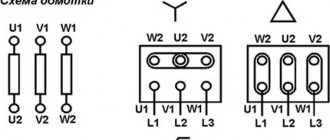
This figure shows how the three phases of an industrial network are connected to the stator windings, but it is not entirely clear from it why one circuit implementation is called a star and the other is called a delta.
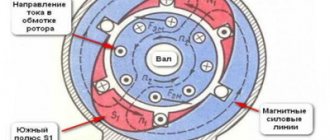
But here everything becomes more or less clear - this is the same drawing, but made from a different angle. As we can see, in a “star” the load (or winding, as in our case) of each of the three phases converges at a single point, which is called neutral. Neutral because the zero (neutral) wire is usually connected to it. In the top picture it is blue, but for simplicity it is not shown below.
As for the “triangle”, here both terminals of each winding are connected to different phases, but not anyhow, but in a certain order: phase A is connected to the beginning of the first winding, phase B is connected to the end, phase B is connected to the beginning of the second winding, to the end - C, and so on. If you mix up the ends of the windings in one of the windings, the engine will not work.
But what is the practical difference between these two schemes? In a star circuit, the burnout of one of the windings will not affect the performance of the remaining two. But if another one burns out, the third one will no longer work. When using a “triangle”, the burnout of two windings is not critical, since the neutral wire is not involved here. And in a star, the neutral wire, as we already know, is connected to the neutral point - this is necessary to ensure equalization of the operating phase currents if the electrical characteristics of the windings are not equal (in the same example with an electric boiler, if heating elements of the same rating are connected differently - one parallel and two in series). If the zero burns out, a phase imbalance will occur, since the voltages will no longer be equalized.
But in a three-phase asynchronous electric motor, the windings in most cases have the same characteristics, so the zero at the neutral point is not always connected.
Start relays
In order to start the electric motor according to the star-delta circuit, special equipment has been developed. The names may be different: “Start-delta” relays, “Start time relays”, etc., but the scheme of their operation is always the same: after voltage is applied to the relay, the acceleration time starts counting, the star starter is turned on, then, at the end During acceleration, the contacts open, the starter turns off, and the contacts that turn on the delta starter close.
Similar relays are produced in the Czech Republic (CRM-2T, TRS2D), Austria (RVP-3, D6DS, VL-32M1), Ukraine (VL-163), Italy (80 series, Finder). They can be modular, programmable, removable, single- or multi-functional, mechanical or digital, daily, weekly - the choice is quite wide.
So, the question: how to connect an electric motor with a star or a triangle is solved quite simply. Carefully read the instructions supplied with the unit, paying special attention to the marks on the motor tag.
Source: www.szemo.ru
Formulas determining voltage, current and power
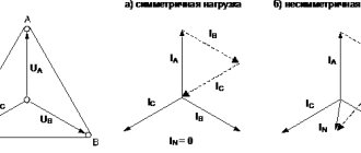
In any three-phase electrical circuit, two types of voltage are distinguished - linear (measured between phases) and phase (measured between phase and zero). In this case, regardless of the nominal line voltage for the star circuit, the phase voltage will be √3 times less, that is, there is a linear relationship between these two types of voltage:
Uline=1.73*Uphase
In this case, the phase and linear currents will be equal to each other:
Iline=Iphase
It follows from this that if the linear voltage is 380 V, then the phase voltage will be 1.73 times less, and this is 220 V.
When connected by a triangle, the opposite is true: the phase and line voltages are identical, but the currents differ with the same correction factor:
Iline=1.73*Iphase
In this case, the formulas for calculating power will be the same regardless of the type of connection:
Stotal=3*Sphase=3*(Ulin/√3)*I =√3*Ulin*I;
Pactive=√3* Ulin*I*cosφ;
Qreactive=√3* Ulin*I*sin φ.
It follows from this that the power of an electric motor whose windings are connected in a star will differ from the same motor with a delta connection by three times.
Let us assume that we have a three-phase asynchronous motor operating from a 380/220 V network. Then, if its star windings are designed for Ulin = 660 V, then when switched to a triangle we get 380 V, which is suitable for our network.
What about power? Same proportion! Let's say, if when connected by a triangle to a three-phase 380 V network, the current value on the stator was 5 A, then the total power of the winding will be equal to:
Stotal=380*√3*5=3287 VA
If you reconnect the triangle to a star, the total power of the stator will decrease threefold, since the voltage on the windings will decrease by √3 times (from 380 to 220 volts), and the current will increase by the same amount.
Then Stotal=380*√3*(5/3)=1070 VA
Let's look at another example. Let us have the same three-phase five-ampere motor, the stator windings of which are connected by a star, but to a 380 V network. Then, when reconnected with a triangle, it will be able to operate from 220 V. But what will happen if, in the latter case, the windings are connected to 380 volts?
Then the total power of the engine will triple, since the voltage on the stator windings has increased by √3 times, as has the current:
Stotal=380*√3*5*(3)=9861 VA
In practice, this means that the electric motor will simply burn out in such a turn of events. That is, you need to use the type of connection in which the voltage corresponds to the nominal voltage.
Defining the type of connection method
The choice of one connection or another depends on:
- reliability of the power grid;
- rated power;
- technical characteristics of the engine itself.
Each connection has its own pros and cons in operation. The engine passport from the manufacturer, as well as on the metal label on the device itself, must indicate its connection diagram.
With a “Star” connection, all ends of the stator windings converge at a water point, and voltage is supplied to the beginning of each of them. Connecting the motor with a star guarantees a smooth, safe start of the unit, but at the initial stage there is a significant loss of load.
The “triangle” connection implies a serial connection of the windings in a closed structure, i.e. the beginning of the first phase is connected to the end of the second and. etc.
Such a connection gives an output power of up to 70% of the rated one, but in this case the starting currents increase significantly, which can cause damage to the electric motor.
There is also a combined star-delta connection (this Y/Δ symbol must appear on the motor housing). The presented circuit causes current surges at the moment of switching, which lead to the rotor speed quickly decreasing and then gradually returning to normal.
Combined circuits are relevant for electric motors with a power of over 5 kW.
How to choose the right scheme
Since the vast majority of asynchronous motors are designed to operate on a 380/220 V network, let's look at what kind of circuit can be used to switch the stator windings.
Industrially manufactured three-phase electric motors are usually equipped with a terminal box that allows you to change one type of connection to another. That is, the terminal block has 6 terminals and three jumpers, and by changing the location of these jumpers, you can quickly and easily change the type of connection of the windings.
But how to determine which type of connection is correct? Everything is simple here: you can use either a star or a triangle, the main thing is that the parameters of the supply network match the characteristics of the engine. Usually all the necessary data is indicated on the nameplate, you just need to be able to interpret it.
A typical case is marking of the following type:
Δ/Y 220/380
This notation means that if the line voltage is 220 V, you need to use a triangle connection diagram for the motor stator windings, if it is a 380 V network, you need to switch them with a star.
The table below shows all valid connection methods:
| Electric motor voltage, V | Mains voltage, V | ||
| 220/127 | 380/220 | 660/380 | |
| 220/127 | Y (star) | – | – |
| 380/220 | Δ (triangle) | Y (star) | – |
| 660/380 | – | Δ (triangle) | Y (star) |
Star-delta switching for smooth starting
So, we have dealt in some detail with the features of connecting stator windings in asynchronous electric motors and found out that, firstly, not all connection methods can be used, taking into account the voltage ratings of the network and the electric motor itself, and, secondly, that these circuits differ in their output characteristics with constant input parameters.
And we also know that starting asynchronous motors requires higher current ratings. Using any of these two types of connection is associated with obvious disadvantages: if the current is sufficient to spin up the motor, then when it reaches operating speeds it will already be excessive, and then the motor will overheat and sooner or later burn out. When using an alternative type of connection, the current will be less, which is good for normal operation, but it may not be enough for starting, that is, the electric motor may simply not start.
The dilemma is solved in a simple and obvious way: by using different types of connections at the start and during the process of reaching operating rotor speeds. The main thing is that there is a triangle symbol on the nameplate, and the motor voltage rating corresponds to the mains voltage.
In practice, this means that in domestic three-phase networks it is possible to use asynchronous electric motors with a voltage rating of 380/660 for the “Δ/Y” connection, respectively.
When the motor is turned on, the stator windings are star-connected and are designed to consume 380 V, although the rating is 660 volts. When the rotor shaft spins up, the automation switches the circuit to a triangle, and then the engine operates at the rated voltage. Switching is usually done using a timer set for a certain time interval from the moment it is turned on. If more precise switching is required, shaft speed or current sensors are used, but such a solution increases the cost of the engine.
In the simplest case, a changeover switch can be used, but more often additional connectors can be used. They complicate the electrical circuit, but have a number of advantages:
- reduce the load on the network, reducing the likelihood of failures in the operation of other electrical equipment due to voltage sags;
- provide a softer start of the electric motor, extending its service life.
Of course, the starting torque is reduced, but this is the lesser of two evils. You can also put up with the need to use two additional three-wire cables connecting the contactors to the motor terminals.
Conclusion
An important condition when using a star-delta connection diagram is the correct calculation of the load on the motor shaft. In addition, it cannot be denied that when the contactor of one connection Y is turned off, and the engine has not yet reached the required speed, the self-induction factor is triggered, and increased voltage enters the network, which can disable other nearby equipment and devices.
Experts recommend starting electric motors with average power according to the Y scheme, this gives soft operation and a smooth start. The methods for selecting switching differ according to the available voltage at the facility and the load.
{SOURCE}
Star-delta switching: how the circuit works
Let's consider the operating algorithm of an asynchronous motor using commutation:
- 380 V is supplied to the beginning of the windings (U1/W1/V1), their ends are connected at one point, that is, we have a star with a voltage of 380 volts instead of 660. But you need to understand that 380 V indicated on the windings is the voltage rating, the effective value will be equal to 220 V;
- in this mode, the motor runs for some time (without load and at low power - about 5 seconds, with load - up to several minutes), which is adjusted using a timer;
- as soon as the timer gives a signal, the supply voltage is completely turned off, but according to the second timer, that is, the shaft rotates by inertia for a short time interval (0.05-0.5 seconds, or several full voltage periods). Such a time pass is necessary to ensure safety - before turning on the “triangular” contactor, the “star” contactor must have time to turn off. And turning off the connector is by no means instantaneous; due to magnetization, it takes just these milliseconds;
- after the second timer is triggered, the connector turns on the triangle circuit and the engine begins to operate in nominal mode, that is, at a stable cruising speed.
The second timer may not be used, but then it is necessary to ensure in some other way that the reconnection to delta is blocked until the star circuit is turned off.
Let's consider how specifically the algorithm described above can be implemented. It will consist of two circuits, which we will call power and control.
Power circuit
Turning on the engine and switching circuits can be implemented in different ways. For example, using the so-called softstarter, or soft starter (common name - soft starter). Sometimes a frequency converter is used, but we will consider the use of contactors, of which we will need three:
- KM1 is a general contactor, the task of which is to supply voltage to the terminals of the windings U1/V1/W1 for the entire operating time of the electric motor;
- KM2 is a contactor that switches the circuit into a star, that is, connecting the terminals of the windings to one point until the engine picks up speed;
- KM3 – contactor for switching the circuit into a “triangle”, switches the motor to operate in normal mode.
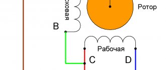
The common contactor in this and other diagrams is indicated in blue.
Green is the color of the KM2 contactor for switching to star.
The KM3 contactor for delta is marked in red.
Control circuit
The operation of these contactors can be organized in several ways:
- use three conventional toggle switches. Cheap and cheerful, but inconvenient;
- use a semi-automatic switch of the 0–Y–Δ type, they are sold ready-made. But you can assemble them yourself using a cam or biscuit-type switch;
- circuit with a timer using a relay;
- use of a specialized relay;
- inclusion of a PLC type controller in the circuit.
If desired, the low-current part of the circuit can be separated from the power part by means of galvanic isolation, which, of course, will complicate the circuit, since it will be necessary to use a transformer or a 24 V power supply, and if possible, then use a 12-volt battery.
We'll take the simple route:
Here element KA1 is added to the circuit, which is a temporary relay that provides a delay during recommutation. It doesn't really matter what type of relay you use - it can be pneumatic or completely electronic. It is only important that the contacts of the relay close some time after power is supplied to KA1.
As for starting the engine, there may also be different options. You can, for example, use a toggle switch or a button, or you can implement a classic-style circuit using self-retaining.
Such a scheme has one, but significant drawback: there is a non-zero probability of conflict between the star and delta contactors. If there is the slightest inaccuracy in the selection of components, the contacts will begin to burn, which often leads to the switching off of the input machine.
To eliminate the risk of accidents, it is necessary to ensure the presence of a lock, possibly electrical, but mechanical is recommended.
If you use a specialized time relay, then it contains two time relays, moreover, based on different principles of operation, and in order to guarantee the required pause between switchings, these two relays are synchronized.
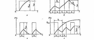
Timing diagrams
Let's consider the timing diagram of the star-delta switch in relation to our circuit implementation.
Here everything is more or less clear, but we need to clarify an important nuance once again: there must be a non-zero gap between the areas corresponding to the activation of KM3 (that is, between the green and red stripes).
If this is not provided, then a situation may arise where two areas intersect. For example, when a reverse-connected diode is included in the circuit, the turn-on time can be 10 times less than the turn-off time.
Implementation of time delay
When using the combined star-delta connection method, a time relay for switching delay is necessary. Experts most often choose one of three methods:
- The first option is carried out using a normally open contact of a time relay. In this case, the RT will turn off the delta connection circuit during startup, and the current relay RT will be responsible for switching.
- The second option involves the use of a modern time relay with a switching delay of 6 to 10 seconds.
- The third method is to control the electric motor contactors with automatic devices or manually.