December 18, 2009
Yageo article ADC/DAC
The year of origin of the Yageo brand is considered to be 1997. However, the company began its activities back in 1994 with the production of precision resistors for computer equipment. In the same year, the company merged with ASJ (a resistor manufacturer from Singapore). In 1996, the German resistor manufacturer Vitrohm joined the company . In 1996-97, a merger took place with the companies Teapo (manufacturer of electrolytic capacitors) and Chilisin (manufacturer of inductive components). After these mergers, the Yageo brand name appeared. In 1999, the American passive components distributor Steller joined Yageo. In 2000, the company included two passive components divisions from Philips Electronics NV - Phycomp and Ferroxcube.
Yageo now produces about 60% of all passive components produced in Taiwan. In terms of production volume of multilayer ceramic chip capacitors (MLCC), Yageo ranks third in the world. The company produces about a third of all resistors produced in the world and does not stop there. Consumers of Yageo products are well-known global electronics manufacturers, including Siemens, Motorola, Samsung, LG, Hewlett Packard (HP), DELL, Acer, Apple, Cisco Systems, Sony Ericsson and many others.
Electrolytic
These surface mount components consist of:
- Aluminum cylindrical body, with a diameter from 4 to 10 mm and a height from 5.4 to 10.5 mm;
- Two sheets of thin foil, separated by paper soaked in electrolyte and rolled into a small roll;
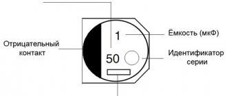
- Two contacts (terminals) that are perpendicular to the centerline of the component. Since electrolytic SMD drives are polar, a negative potential is connected to one of the contacts, indicated by a special strip at the end of the case, and a positive potential is connected to the second.
- A mounting pad designed to secure a component to a work surface.
Various models of these components, rated from 1 to 1000-150 μF, are capable of operating at voltages from 4 to 1000 V.
Passive components: Electrolytic capacitors
| TYPE: | Type Explanation: | ||||
| S.E. | Aluminum Capacitor Aluminum capacitor (polar component) | ||||
| Case diameter | Case height | Tape width | Component pitch in the ribbon | Qty per standard package (180 mm/7 inches) plastic tape | Qty per standard pack (330 mm/13 inches) plastic tape |
| 3 mm | 5.5 mm | 12 mm | 8 mm | 100 | 2000 |
| 4 mm | 5.5 mm | 12 mm | 8 mm | 100 | 2000 |
| 5 mm | 5.5 mm | 12 mm | 12 mm | 100 | 1000 |
| 6.3 mm | 5.5 mm | 16 mm | 12 mm | 100 | 1000 |
| 8 mm | 6 mm | 16 mm | 12 mm | 100 | 1000 |
| 8 mm | 10 mm | 24 mm | 16 mm | 100 | 500 |
| 10 mm | 10 mm | 24 mm | 16 mm | 100 | 300 — 500 |
| 10 mm | 14 - 22 mm | 32 mm | 20 mm | — | 250 — 300 |
| 12.5 mm | 14 mm | 32 mm | 24 mm | — | 200 — 250 |
| 12.5 mm | 17 mm | 32 mm | 24 mm | — | 150 — 200 |
| 12.5 mm | 22 mm | 32 mm | 24 mm | — | 125 — 150 |
| 16 mm | 17 mm | 44 mm | 28 mm | — | 125 — 150 |
| 16 mm | 22 mm | 44 mm | 28 mm | — | 75 — 100 |
| 18 mm | 17 mm | 44 mm | 32 mm | — | 125 — 150 |
| 18 mm | 22 mm | 44 mm | 32 mm | — | 75 — 100 |
| 20 mm | 17 mm | 44 mm | 36 mm | — | 50 |
The website catalog.compel.ru is an effective tool for searching for electronic components
To quickly search for electronic components according to specified parameters, it is best to use the website catalog.compel.ru . The website presents most of the electronic components supplied by COMPEL. To perform a parametric search, you first need to select a component type. For example, for ceramic chip capacitors the following search path is required: Passive Components ® Capacitors ® Ceramic. In this case, a window will appear on the site (Figure 10) with the ability to set the necessary parameters.
Rice. 10. Window for searching for ceramic capacitors with the ability to set specific parameters
It is recommended to use the website viewing program (browser) “Google Chrome”. Working in this browser speeds up the search several times. To search for a chip capacitor with a capacity of 0.01 μF with an X7R dielectric, you need to specify a specific capacitor value of 0.01 μF and select the X7R dielectric type. If we select a specific Yageo brand, we get the results shown in Figure 11.
Rice. 11. Search results for 0.01uF ceramic chip capacitor with X7R dielectric
Clicking on the name of a position that matches the parameters opens a new window, which will show the availability in stock and the price of the component depending on the quantity. Most ceramic capacitors are entered into the database as CERCAP... Instead of an ellipsis, the capacitance rating, permissible operating voltage, housing dimensions, and dielectric type are indicated. The first letter in the dielectric type encodes the accuracy of the capacitor rating. For example, the letter "K" corresponds to an accuracy of ±10%.
Resistors and inductive components can be found in a similar way. Most chip resistors are listed in the database as RES... Instead of an ellipsis, the package size, resistor value and its accuracy are indicated. When you click on a specific position of the resistor, you can see the name from the manufacturer (Partnumber) on a new Internet page that opens.
Questions about products and search can be asked by writing an email to [email protected] .
Obtaining technical information, ordering samples, delivery - e-mail
•••
Resistors
Passive Components: Resistors
| TYPE: | Type Explanation: | |||||
| S.R. | Resistor Chip Resistor chip | |||||
| Size (inches) | Size(mm) | Component Thickness | Tape width | Component pitch in the ribbon | Quantity in standard packaging (180 mm/7 inches) paper tape | Qty per standard package (180 mm/7 inches) plastic tape |
| 01005 | 0402 | 0.12 mm ± 0.02 | 8 mm | 2 mm | 20000 | — |
| 0201 | 0603 | 0.23 mm ± 0.03 | 8 mm | 2 mm | 15000 | — |
| 0402 | 1005 | 0.35 mm ± 0.05 | 8 mm | 2 mm | 10000 | — |
| 0603 | 1608 | 0.45 mm ± 0.1 | 8 mm | 4 mm | 5000 | — |
| 0805 | 2012 | 0.55 mm ± 0.1 | 8 mm | 4 mm | 5000 | — |
| 1206 | 3216 | 0.55 mm ± 0.15 | 8 mm | 4 mm | 5000 | — |
| 1210 | 3225 | 0.55 mm ± 0.15 | 8 mm | 4 mm | 5000 | 4000 |
| 2010 | 5025 | 0.55 mm ± 0.15 | 8/12 mm | 4/8 mm | — | 4000 |
| 2512 | 6332 | 0.55 mm ± 0.15 | 12 mm | 4/8 mm | — | 4000/2000 |
Passive Components: Resistors
| TYPE: | Type Explanation: | ||||
| SRM | Melf Resistor Melf resistor (round) | ||||
| Size (inches) | Name | Component size | Tape width | Component pitch in the ribbon | Qty per standard package (180 mm/7 inches) plastic tape |
| 0604 | — | 1.6 mm X 1.0 mm | 8 mm | 4 mm | 3000 |
| 0805 | Micro | 2.2 mm X 1.1 mm | 8 mm | 4 mm | 3000 |
| 1206 | Mini | 3.2 mm X 1.6 mm | 8 mm | 4 mm | 3000 |
| 1406 | Mini | 3.5 mm X 1.4 mm | 8 mm | 4 mm | 3000 |
| 2308 | Melf | 5.9 mm X 2.2 mm | 12 mm | 4 mm | 1500 |
Trimmer SMD resistors
Color coding of resistors
Products in this category are available in open and closed versions. Some models are equipped with a sealed housing to ensure long-term performance in conditions of high humidity (dust pollution of the atmosphere).
Trimmer SMD resistors in factory packaging
There is no single standard size for trimmer resistors. Manufacturers independently determine the labeling system and approve the rules with special regulations.
Ceramic components
In ceramic elements, porcelain or similar inorganic materials are used as a dielectric. The main advantage of such products is their resistance to high temperatures and the ability to produce products of extremely small sizes.
Important! SMD ceramic capacitors are also installed by soldering onto a printed circuit board.
Visually, such an element, as a rule, resembles a small brick to which contact pads are soldered at the ends.
Ceramic SMD capacitors
Unlike radio components of standard sizes, SMD elements of small size are first glued to the board, and only then the leads are soldered. In production, ceramic products of this type are installed by special automatic machines.
Marking of ceramic SMD capacitors
Small ceramic SMD capacitors are marked with an alphanumeric code consisting of 3 characters. The first indicates the minimum operating temperature, for example:
- Z - from 10 °C;
- Y - from −30 °С;
- X - from 55 °C.
Marking of SMD capacitors
The second symbol indicates the upper limit of heating of the radio component:
- 2 - up to 45 °C;
- 4 - up to 65 °C;
- 5 - up to 85 °C;
- 6 - up to 105 °C;
- 7 - up to 125 °C;
- 8 - up to 150 °C;
- 9 - up to 200 °C.
The third character indicates the accuracy of the electronic component:
- A - up to ± 1.0%;
- B - up to ± 1.5%;
- C - up to ± 2.2%;
- D - up to ± 3.3%;
- E - up to ± 4.7%;
- F - up to ± 7.5%;
- P - up to ± 10%;
- R - up to ± 15%;
- S - up to ± 22%;
- T - up to ± 33%;
- U - up to ± 56%;
- V - up to ± 82%.
The capacity of small ceramic SMD capacitors is indicated in picofarads. To save the area of a small radio element, the main mantissa number is encoded in a letter of the Latin alphabet. The table below provides a complete list of such designations.
Table with encoded characters
After the number, the multiplier is indicated, for example, the designation on a ceramic capacitor X3 means that the capacitor has a capacity of 7.5 * 10 ^ 3 Pf.
Note! The code indicating the capacity of a ceramic SMD capacitor may be preceded by a Latin letter, which indicates the brand of the manufacturer of the electronic component.
If the area of this type of ceramic capacitor is large enough, then the dielectric type can be displayed on it. For this purpose the following are used:
- NP0. The dielectric constant of such an element is at an extremely low level. The main advantage of components of this type is their good resistance to sudden temperature changes. The disadvantage of elements that use this type of dielectric is their high price;
- X7R. Average quality dielectric. Products that use this type of insulator do not have excellent breakdown resistance characteristics, but in the average temperature range they are able to work significantly longer than many more expensive elements;
- Z5U. A dielectric with high electrical permeability values, but the downside of this indicator is that the capacitance error is too large;
- Y5V. The insulating material has approximately the same characteristics as Z5U. In terms of cost, this dielectric is the cheapest, so electrical components made on its basis are sold at the lowest prices.
You may be interested in this. What is the unit of measurement for current?
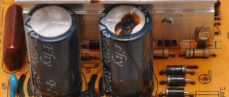
Burnt SMD capacitor
Considering all of the above, you can be sure that if the SMD capacitor has not burned or changed the color of the surface for other reasons, then you can always determine its value by the markings on its body.
Passive Components: Capacitors
| TYPE: | Type Explanation: | |||||
| S.C. | Ceramic Chip Capacitor Ceramic chip capacitor | |||||
| Size (inches) | Size(mm) | Component Thickness | Tape width | Component pitch in the ribbon | Quantity in standard packaging (180 mm/7 inches) paper tape | Qty per standard package (180 mm/7 inches) plastic tape |
| 01005 | 0402 | 0.2 mm ± 0.03 | 8 mm | 2 mm | 20000 | — |
| 0201 | 0603 | 0.3 mm ± 0.03 | 8 mm | 2 mm | 15000 | — |
| 0402 | 1005 | 0.5 mm ± 0.1 | 8 mm | 2 mm | 10000 | — |
| 0603 | 1608 | 0.8 mm ± 0.1 | 8 mm | 4 mm | 4000 | — |
| 0805 | 2012 | 0.6 – 1.25 mm | 8 mm | 4 mm | 4000 | 3000 |
| 1206 | 3216 | 0.6 – 1.25 mm | 8 mm | 4 mm | 4000 | 3000 |
| 1210 | 3225 | 1.25 mm – 1.5 mm | 8 mm | 4 mm | — | 3000 |
| 1812 | 4532 | 2 mm (Max.) | 12 mm | 8 mm | — | 1000 |
| 2225 | 5664 | 2 mm (Max.) | 12 mm | 8 mm | — | 1000 |
Yageo electrolytic capacitors
Yageo produces electrolytic capacitors with radial leads, with snap-in rigid leads for mechanical fixation on the printed circuit board, and also electrolytic capacitors for surface mounting. The series and main parameters of these capacitors are shown in Figure 6.
Rice. 6. Yageo electrolytic capacitors
Radial lead capacitors are divided into general purpose series, miniature size, low equivalent series resistance (ESR) and specialty capacitors (low leakage current, non-polar and long life up to 10 thousand hours at 105°C). When choosing electrolytic capacitors, you need to take into account that their capacitance and ESR are highly dependent on the ambient temperature. Figure 7 shows typical frequency dependences of impedance (Z) for temperatures of -40, 20 and 85°C. The impedance for the entire operating temperature range can differ tens of times, so when calculating the circuit you need to focus on the parameters of electrolytic capacitors at the minimum operating temperature.
Rice. 7. Typical frequency dependences of the impedance of an electrolytic capacitor for different temperatures
The end of the guaranteed service life of an electrolytic capacitor does not mean its catastrophic failure, but only a decrease in capacity below the permissible value specified in the technical documentation (usually the permissible deviation is 20%). By lowering the operating temperature of the electrolytic capacitor body, its lifespan can be significantly increased. The service life doubles for every 10°C decrease in housing temperature, but this rule only applies up to a temperature of about 40°C. Below this value, increasing the service life does not lead to significant results.
From all this it follows that to increase service life it is necessary to select capacitors with a high maximum permissible operating temperature (105 ° C or more). If the operating temperature of the case is no more than 85°C, then the expected life time of the capacitor will be four times longer. For example, if we take an electrolytic capacitor with a guaranteed operating time of 1000 hours at 105°C and use it at an operating temperature of no more than 85°C and take into account that a decrease in temperature for every 10°C doubles the lifespan, then, in theory, we get a fourfold increase in time operation up to 4000 hours. It should be borne in mind that this is an empirical rule, so such calculations should be treated with great attention, since the lifetime also depends on the magnitude of the ripple current.
Description and purpose of tantalum capacitors
Modern tantalum capacitors are small in size and belong to chip components that are designed for mounting on a board. Otherwise, such parts are called SMD, which stands for “surface mount components.” SMD parts are convenient for automated mounting and soldering processes on printed circuit boards.
The main purpose of electrolytic polarized tantalum capacitors is to act in conjunction with a resistor to process the signal and smooth out its peaks and sharp pulses.
Capacitors are widely used in automotive, industrial, digital, and aerospace applications.
Yageo chip varistors
To protect circuits from electrostatic discharge, Yageo produces chip varistors in packages 0402, 0603, 0805 and 1206. A varistor is a semiconductor resistor with a pronounced nonlinearity of the current-voltage characteristic. The resistance of a varistor depends on the voltage applied to it. The varistor is connected in parallel with the protected load or the input of the device. When a pulse noise occurs, the varistor sharply reduces its resistance due to the nonlinearity of its characteristic and shunts the load. The interference energy is dissipated by the varistor, which ensures that dangerous voltage pulses are “cut off” and the interference current flows through the metal body of the device and protective grounding. This is illustrated in Figure 8.
Rice. 8. Protection of the device input from electrostatic discharge using a varistor
The Yageo chip varistor coding system is shown in Figure 9.
Rice. 9. Yageo chip varistor designation system
Main parameters of tantalum capacitors
To determine a safe operating mode, it is necessary to calculate the levels of permitted current and voltage values. For calculations, you need to know the following parameters of tantalum capacitors, which are reflected in the documentation:
- Nominal capacity.
These devices have high specific capacitance, which can be thousands of microfarads. - Rated voltage.
Modern models of these devices are mostly designed for voltages up to 75 V. Moreover, for normal operation in an electrical circuit, the part must be used at voltages that are less than the nominal one. Operating tantalum capacitors at voltages up to 50% of the rated voltage reduces the failure rate to 5%. - Impedance (total resistance).
Contains inductive component, parallel resistance, series equivalent resistance (ESR). - Maximum power dissipation.
When AC voltage is applied to a tantalum device, heat is generated. The permissible increase in the temperature of the capacitor due to the released power is established experimentally.
Physical quantities used in marking the capacitance of ceramic capacitors
To determine the value of capacitance in the international system of units (SI), the Farad (F, F) is used. This is too large a value for a standard electrical circuit, so smaller units are used in marking household capacitors.
Table of capacitance units used for household ceramic capacitors
Unit name
| Designation options | Power relative to Farad | ||
| Microfarad | Microfarad | µF, µF, uF, mF | 10-6F |
| Nanofarad | Nanofarad | nF, nF | 10-9F |
| Picofarad | Picofarad | pF, pF, mmF, uuF | 10-12F |
The off-label unit millifarad is rarely used - 1 mF (10-3F).
Marking of tantalum capacitors
The markings of capacitors indicate standard parameters: capacitance, rated voltage, polarity. On cases of types B, C, D, E, V, all parameters are displayed, and on case of type A, instead of the voltage rating, its letter code is indicated. The marking may indicate additional information - the manufacturer’s logo, production date code, etc.
Voltage Code Table for Type A Enclosures
| Rated voltage | Code | Rated voltage | Code |
| 4,0 | G | 20 | D |
| 6,3 | J | 25 | E |
| 10 | A | 35 | V |
| 16 | C | 50 | T |
Types of tantalum capacitor housings and their sizes
Tantalum capacitors
Passive components: Tantalum capacitors
| TYPE: | Type Explanation: | |||||
| SD | Molded Tantalum Tantalum capacitor (polar component) | |||||
| Size (inches) | Code | Component Thickness | Component size | Tape width | Component pitch in the ribbon | Qty per standard package (180 mm/7 inches) plastic tape |
| 3216 | A | 1.6 mm | 3.2 mm X 1.6 mm | 8 mm | 4 mm | 2000 |
| 3528 | B | 1.9 mm | 3.5 mm X 2.8 mm | 8 mm | 4 mm | 2000 |
| 6032 | C | 2.5 mm | 6.0 mm X 3.2 mm | 12 mm | 8 mm | 500 |
| 7343 | D | 2.8 mm | 7.3 mm X 4.3 mm | 12 mm | 8 mm | 500 |
| 1608 | J | 0.8 mm | 1.6 mm X 0.8 mm | 8 mm | 4 mm | 4000 |
| 2012 | P/R | 1.2 mm | 2.0 mm X 1.2 mm | 8 mm | 4 mm | 2500/3000 |
Yageo inductor chip
Yageo produces a fairly wide range of chip inductors. Table 5 shows the parameters of only a small part of the chip inductors of this company (only the most popular).
Table 5. Yageo SMD Chip Inductors
| Series | Z (impedance), Ohm | Rated current, A | Test frequencies, MHz | DCR*, Ohm | Dimensions |
| YSB | 6…2700 | 0,05…0,6 | 30…100 | 0,05…2 | 1005, 1608, 2012, 3216, 3225, 4516, 4532 |
| YPB | 10…1500 | 0,8…6 | 50…100 | 0,01…0,25 | |
| YNB | 6…2700 | 0,05…0,8 | 100 | 0,05…1,0 | 1005, 1608, 2012, 3216 |
| *DCR – Direct Current Resistance – inductor resistance at direct current. | |||||
The old names of the series shown in the table do not have the first letter Y (the first letter of the Yageo company name). This letter is present in the new names, which emphasizes that the series belongs to the Yageo company. The maximum current of Yageo chip inductors reaches 6 A. For higher current values, surface mount inductors are available in SMT packages.
Dimensions and types of SMD component housings
Two-pin components: rectangular, passive (resistors and capacitors)
The size designation consists of four digits. The first two correspond roundly to the length L in the accepted measurement system (either metric or inch), and the last two correspond to the width W.
| Size (inch system) | Size (Metric) | Size(mm) |
| 008004 | 0201 | 0.25×0.125 |
| 009005 | 03015 | 0.3×0.15 |
| 01005 | 0402 | 0.4×0.2 |
| 0201 | 0603 | 0.6×0.3 |
| 0402 | 1005 | 1.0×0.5 |
| 0603 | 1608 | 1.6×0.8 |
| 0805 | 2012 | 2.0×1.25 |
| 1008 | 2520 | 2.5×2.0 |
| 1206 | 3216 | 3.2×1.6 |
| 1210 | 3225 | 3.2×2.5 |
| 1806 | 4516 | 4.5×1.6 |
| 1812 | 4532 | 4.5×3.2 |
| 1825 | 4564 | 4.5×6.4 |
| 2010 | 5025 | 5.0×2.5 |
| 2512 | 6332 | 6.3×3.2 |
| 2725 | 6863 | 6.9×6.3 |
| 2920 | 7451 | 7.4×5.1 |
Two-pin components: cylindrical, passive (resistors and diodes) in MELF package
| frame | dimensions (mm) and other parameters |
| Melf (MMB) 0207 | L = 5.8 mm, Ø = 2.2 mm, 1.0 W, 500 V |
| MiniMelf (MMA) 0204 | L = 3.6 mm, Ø = 1.4 mm, 0.25 W, 200 V |
| MicroMelf (MMU) 0102 | L = 2.2 mm, Ø = 1.1 mm, 0.2 W, 100 V |
Two-terminal components: tantalum capacitors
| type | dimensions (mm) |
| A (EIA 3216-18) | 3,2 × 1,6 × 1,6 |
| B (EIA 3528-21) | 3,5 × 2,8 × 1,9 |
| C (EIA 6032-28) | 6,0 × 3,2 × 2,2 |
| D (EIA 7343-31) | 7,3 × 4,3 × 2,4 |
| E (EIA 7343-43) | 7,3 × 4,3 × 4,1 |
Two-terminal components: diodes (small outline diode, abbr. SOD)
| designation | dimensions (mm) |
| SOD-323 | 1,7 × 1,25 × 0,95 |
| SOD-123 | 2,68 × 1,17 × 1,60 |
Three-Terminal Components: Short Terminal Transistors (SOT)
| designation | dimensions (mm) |
| SOT-23 | 3 × 1,75 × 1,3 |
| SOT-223 | 6,7 × 3,7 × 1,8 |
| DPAK (TO-252) | package (three- or five-pin options) designed by Motorola for high-heat semiconductor devices |
| D2PAK (TO-263) | package (three-, five-, six-, seven- or eight-pin options), similar to DPAK, but larger in size (as a rule, the package dimensions correspond to the TO220 dimensions) |
| D3PAK (TO-268) | body similar to D2PAK, but even larger in size |
Multi-pin components: terminals in two lines on the sides
| designation | pin spacing (mm) |
| IC - with small-outline integrated circuit (SOIC) | 1,27 |
| TSOP - (English thin small-outline package) thin SOIC (thinner in height than SOIC) | 0,5 |
| SSOP - Seated SOIC | 0,65 |
| TSSOP - Thin Seated SOIC | 0,65 |
| QSOP - Quarter Size SOIC | 0,635 |
| VSOP - even smaller QSOP | 0.4; 0.5 or 0.65 |
Multi-pin components: terminals in four lines on the sides
| designation | pin spacing (mm) |
| PLCC, CLCC - IC in a plastic or ceramic package with leads bent under the package in the form of the letter J | 1,27 |
| QFP - (English quad flat package) - square flat IC packages | different sizes |
| LQFP - low profile QFP | 1.4mm high different sizes |
| PQFP - plastic QFP (44 or more pins) | different sizes |
| CQFP - ceramic QFP (similar to PQFP) | different sizes |
| TQFP - thinner than QFP | thinner than QFP |
| PQFN - power QFP | no leads, pad for radiator |
Multi-Pin Components: Pin Array
| designation | pin spacing (mm) |
| BGA - (English ball grid array) - an array of balls with square or rectangular pinouts | 1,27 |
| LFBGA - low profile FBGA, square or rectangular, solder balls | 0,8 |
| CGA - package with input and output pins made of refractory solder | different sizes |
| CCGA - Ceramic CGA | different sizes |
| μBGA - (micro-BGA) - ball array | distance between balls less than 1 mm |
| FCBGA - (English flip-chip ball grid array) an array of balls on a substrate, a crystal with a heat spreader is soldered to the substrate | different sizes |
| PBGA - ball array, crystal inside a plastic case | different sizes |
| LLP - leadless package | — |
Methods for marking capacitor capacity
On Soviet-made parts, most often having a fairly large surface area, the numerical values of the capacitance, its unit of measurement and the nominal voltage in volts were applied. For example, 23 pF, that is, 23 picofarads.
Deciphering the markings of modern ceramic capacitors of domestic and foreign production is a more complex undertaking. The following options are possible.
Three digits
If the marking contains three digits, then the first two indicate the capacity value, the last one is the zero multiplier. If the last digit is in the range 0-6, then the specified number of zeros is added to the number consisting of the first two digits. If the last digit is 8, then the number from the first two digits is multiplied by 0.01, if 9, then by 0.1. After determining the numerical value of the capacity, it is necessary to set the unit of measurement. The capacitance of small parts is usually measured in picofarads. After the numerical value there may be a letter indicating the unit of measurement: p – picofarad, µ – microfarad, n – nanofarad.
Example 353p = 35 x 103 pF.
Four digits
This option is similar to the one described above. Only the significant part contains three digits, and the fourth is the exponent for 10. The unit of measurement is usually picofarads.
Alphanumeric marking
With this method of designating a container, the letter indicates the place where the comma should be. The letter R is used to mark capacitance in microfarads. If there is a 0 in front of the letter R, then the unit of measurement is picofarad. For example, 0R4 = 4 pF, R47 = 0.45 µF.
The functions of a decimal point can be performed by a letter indicating a unit of measurement. For example, a capacitance of 0.43 μF on imported capacitors
designated as m43 or µ43. In the Russian version, the letters “p” are used as a decimal point – picofarads, “n” – nanofarads, “m” – microfarads.
In some cases, tolerances are applied to the capacitor housing for the nominal value of the capacitance. On large-area parts, they are indicated by numbers indicating the percentage of tolerance. For small capacitors, tolerances are usually marked in coded form.
Tolerance letter coding table
| Letter designation | Tolerance, % | Letter designation | Tolerance, % |
| B | +/- 0,1 | M | +/- 20 |
| C | +/- 0,25 | N | +/- 30 |
| D | +/- 0,5 | Q | -10…+30 |
| F | +/- 1 | T | -10…+50 |
| G | +/- 0,2 | Y | -10…+100 |
| J | +/- 0,5 | S | -20…+50 |
| K | +/- 10 | Z | -20…+80 |
How to determine the capacitance, rating and voltage of SMD capacitors
Above, detailed information was provided on how to correctly determine the rating of SMD capacitors by marking. The main difficulty in performing such an operation is that the characters may be so small that they cannot be identified with the naked eye. In such a situation, it is recommended to use a magnifying glass or any other magnifying device with a suitable magnification, as well as install high-quality lighting in the place where such studies are carried out.
Radio amateur magnifier
Note! Sometimes the markings on the surface of the radio element are not readable or are completely missing, so every radio amateur should know how to determine the capacitance of an electrolytic capacitor without markings. To perform such work, you cannot do without a special measuring device.
How to determine the capacitance of an SMD capacitor without markings using a device
To obtain correct indicators, before starting to measure the capacitance of the capacitor, the radioelement must be completely discharged.
The voltage limit is measured on a capacitor, which is installed in an electronic circuit where the element can be safely connected to electrical voltage. After turning off the current source, measure the voltage at the contacts of the radio component. The resulting value in volts should be multiplied by 1.5 to obtain the exact value of this parameter.
Voltage can be measured with a cheap multimeter
SMD capacitors are very convenient for self-assembly of various circuits, and during automatic installation, thanks to them, it is possible to achieve maximum compactness in the arrangement of radio components. Knowing the principles of deciphering the designation of such elements, you can design and assemble even complex devices at home without any difficulty.
Sources
- https://amperof.ru/sovety-elektrika/sdm-kondensatory-bez-markirovki.html
- https://micpic.ru/spravochniki/159-razmery-smd-korpusov.html
- https://radio-magic.ru/smd-razmerj
- https://rusenergetics.ru/polezno-znat/smd-kondensatory-bez-markirovki-kak-opredelit
- https://www.RadioElementy.ru/articles/tantalovye-kondensatory/
- https://global-smt.ru/articles/surface-mount_technology/
What are SMD capacitors and what are they for?
Many electronic components are large in size and are mounted on the board using wire taps or wide legs, similar to microcircuits. For reliable fixation, the contact elements of such parts are installed in specially made holes, in which they are coated with molten solder to ensure high-quality electrical contact.
Standard installation of radio components
If the power dissipation of resistors or the value of capacitors is too small, then there is no need to make such a product too bulky. Installing elements of this type by drilling the board would force electronic circuit designers to allocate an unreasonably large area of the printed circuit for their installation. The logical solution to this problem is to use SMD components.
SMD technology (Surface Mounted Device) is a method of installing electronic parts without drilling the board. Such a component is simply soldered on one side of the surface, thereby saving significant area without reducing its strength by the presence of a large number of micro-holes.
Note! The surface mounting method can be used to install not only capacitors, but also resistors, transistors and microcircuits.
The use of SMD components allows for maximum optimization of the arrangement of parts on the board. Thanks to the use of this technology, circuits for complex devices can be manufactured in relatively small sizes, which is especially important when designing mobile products.
Satellite television
The capacitance of capacitors can be measured in microfarads (uF), nanofarads (nF), picofarads (pF) and is designated by a special code. This table will help you understand the markings for various measuring ratings and select the necessary analogs for replacement. There is a universal measuring device for radio components. Can measure inductance, ESR and losses of electrolytic capacitors. It also checks transistors (including MOSFETs), diodes, zener diodes, and quartz. The type of parts is determined automatically and displays the values. In this ESR tester review, I described this device.
| uF (uF) | nF | pF (pF) | Code |
| 1uF | 1000nF | 1000000pF | 105 |
| 0.82uF | 820nF | 820000pF | 824 |
| 0.8uF | 800nF | 800000pF | 804 |
| 0.7uF | 700nF | 700000pF | 704 |
| 0.68uF | 680nF | 680000pF | 624 |
| 0.6uF | 600nF | 600000pF | 604 |
| 0.56uF | 560nF | 560000pF | 564 |
| 0.5uF | 500nF | 500000pF | 504 |
| 0.47uF | 470nF | 470000pF | 474 |
| 0.4uF | 400nF | 400000pF | 404 |
| 0.39uF | 390nF | 390000pF | 394 |
| 0.33uF | 330nF | 330000pF | 334 |
| 0.3uF | 300nF | 300000pF | 304 |
| 0.27uF | 270nF | 270000pF | 274 |
| 0.25uF | 250nF | 250000pF | 254 |
| 0.22uF | 220nF | 220000pF | 224 |
| 0.2uF | 200nF | 200000pF | 204 |
| 0.18uF | 180nF | 180000pF | 184 |
| 0.15uF | 150nF | 150000pF | 154 |
| 0.12uF | 120nF | 120000pF | 124 |
| 0.1uF | 100nF | 100000pF | 104 |
| 0.082uF | 82nF | 82000pF | 823 |
| 0.08uF | 80nF | 80000pF | 803 |
| 0.07uF | 70nF | 70000pF | 703 |
| 0.068uF | 68nF | 68000pF | 683 |
| 0.06uF | 60nF | 60000pF | 603 |
| 0.056uF | 56nF | 56000pF | 563 |
| 0.05uF | 50nF | 50000pF | 503 |
| 0.047uF | 47nF | 47000pF | 473 |
| 0.04uF | 40nF | 40000pF | 403 |
| 0.039uF | 39nF | 39000pF | 393 |
| 0.033uF | 33nF | 33000pF | 333 |
| 0.03uF | 30nF | 30000pF | 303 |
| 0.027uF | 27nF | 27000pF | 273 |
| 0.025uF | 25nF | 25000pF | 253 |
| 0.022uF | 22nF | 22000pF | 223 |
| 0.02uF | 20nF | 20000pF | 203 |
| 0.018uF | 18nF | 18000pF | 183 |
| 0.015uF | 15nF | 15000pF | 153 |
| 0.012uF | 12nF | 12000pF | 123 |
| 0.01uF | 10nF | 10000pF | 103 |
| 0.0082uF | 8.2nF | 8200pF | 822 |
| 0.008uF | 8nF | 8000pF | 802 |
| 0.007uF | 7nF | 7000pF | 702 |
| 0.0068uF | 6.8nF | 6800pF | 682 |
| 0.006uF | 6nF | 6000pF | 602 |
| 0.0056uF | 5.6nF | 5600pF | 562 |
| 0.005uF | 5nF | 5000pF | 502 |
| 0.0047uF | 4.7nF | 4700pF | 472 |
| 0.004uF | 4nF | 4000pF | 402 |
| 0.0039uF | 3.9nF | 3900pF | 392 |
| 0.0033uF | 3.3nF | 3300pF | 332 |
| 0.003uF | 3nF | 3000pF | 302 |
| 0.0027uF | 2.7nF | 2700pF | 272 |
| 0.0025uF | 2.5nF | 2500pF | 252 |
| 0.0022uF | 2.2nF | 2200pF | 222 |
| 0.002uF | 2nF | 2000pF | 202 |
| 0.0018uF | 1.8nF | 1800pF | 182 |
| 0.0015uF | 1.5nF | 1500pF | 152 |
| 0.0012uF | 1.2nF | 1200pF | 122 |
| 0.001uF | 1nF | 1000pF | 102 |
| 0.00082uF | 0.82nF | 820pF | 821 |
| 0.0008uF | 0.8nF | 800pF | 801 |
| 0.0007uF | 0.7nF | 700pF | 701 |
| 0.00068uF | 0.68nF | 680pF | 681 |
| 0.0006uF | 0.6nF | 600pF | 621 |
| 0.00056uF | 0.56nF | 560pF | 561 |
| 0.0005uF | 0.5nF | 500pF | 52 |
| 0.00047uF | 0.47nF | 470pF | 471 |
| 0.0004uF | 0.4nF | 400pF | 401 |
| 0.00039uF | 0.39nF | 390pF | 391 |
| 0.00033uF | 0.33nF | 330pF | 331 |
| 0.0003uF | 0.3nF | 300pF | 301 |
| 0.00027uF | 0.27nF | 270pF | 271 |
| 0.00025uF | 0.25nF | 250pF | 251 |
| 0.00022uF | 0.22nF | 220pF | 221 |
| 0.0002uF | 0.2nF | 200pF | 201 |
| 0.00018uF | 0.18nF | 180pF | 181 |
| 0.00015uF | 0.15nF | 150pF | 151 |
| 0.00012uF | 0.12nF | 120pF | 121 |
| 0.0001uF | 0.1nF | 100pF | 101 |
| 0.000082uF | 0.082nF | 82pF | 820 |
| 0.00008uF | 0.08nF | 80pF | 800 |
| 0.00007uF | 0.07nF | 70pF | 700 |
| 0.000068uF | 0.068nF | 68pF | 680 |
| 0.00006uF | 0.06nF | 60pF | 600 |
| 0.000056uF | 0.056nF | 56pF | 560 |
| 0.00005uF | 0.05nF | 50pF | 500 |
| 0.000047uF | 0.047nF | 47pF | 470 |
| 0.00004uF | 0.04nF | 40pF | 400 |
| 0.000039uF | 0.039nF | 39pF | 390 |
| 0.000033uF | 0.033nF | 33pF | 330 |
| 0.00003uF | 0.03nF | 30pF | 300 |
| 0.000027uF | 0.027nF | 27pF | 270 |
| 0.000025uF | 0.025nF | 25pF | 250 |
| 0.000022uF | 0.022nF | 22pF | 220 |
| 0.00002uF | 0.02nF | 20pF | 200 |
| 0.000018uF | 0.018nF | 18pF | 180 |
| 0.000015uF | 0.015nF | 15pF | 150 |
| 0.000012uF | 0.012nF | 12pF | 120 |
| 0.00001uF | 0.01nF | 10pF | 100 |
| 0.000008uF | 0.008nF | 8pF | 080 |
| 0.000007uF | 0.007nF | 7pF | 070 |
| 0.000006uF | 0.006nF | 6pF | 060 |
| 0.000005uF | 0.005nF | 5pF | 050 |
| 0.000004uF | 0.004nF | 4pF | 040 |
| 0.000003uF | 0.003nF | 3pF | 030 |
| 0.000002uF | 0.002nF | 2pF | 020 |
| 0.000001uF | 0.001nF | 1pF | 010 |
Very often, to carry out repair work on electronic devices, it is necessary to have capacitors of various ratings in stock. Since it is often not possible to purchase something for all occasions in the store, in most cases I order from my Chinese friends on the Aliexpress site. Electrolytic capacitors are also available for sale in a larger range. Can be purchased in sets of 10-20 different denominations.
Capacitors on Aliexpress
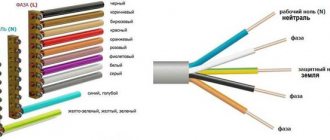
Color coding of ceramic capacitors
Color coding is often used for capacitors with small surface area. Color stripes are applied from top to bottom or left to right. The nominal capacity is usually indicated by 3-5 colored stripes, the first two of which indicate a specific number. Black – 0, brown – 1, red – 2, orange – 3, yellow – 4, green – 5, blue – 6, purple – 7, gray – 8, white – 9.
The number, which is made up of the numbers encoded in the first two stripes, is multiplied by the multiplier encrypted in the third strip. The orange stripe means 103, yellow – 104, green – 105.
The marking may contain a fourth stripe, the color of which corresponds to the permissible deviations from the nominal capacity. White means 10% deviation in both directions is acceptable, and black means 20% in both directions. The fifth strip characterizes the voltage rating. Red – 250 V, yellow – 400 V.