Hello, dear readers of the site. Intermediate electromagnetic relays are used in many electronic and electrical circuits and are designed for switching electrical circuits. They are used to amplify and transform electrical signals; remembering information and programming; distribution of electrical energy and control of the operation of individual elements, devices and equipment units; coupling of elements and devices of radio-electronic equipment operating at different voltage levels and operating principles; in alarm, automation, protection circuits, etc.
An intermediate electromagnetic relay is an electromechanical device that can switch electrical circuits and also control another electrical device. Electromagnetic relays are divided into permanent
and
alternating current
.
The operation of an electromagnetic relay is based on the interaction of the magnetic flux of the winding and a moving steel armature, which is magnetized by this flux. The figure shows the appearance of the RP-21 type intermediate relay.
Relay device.
The relay is a coil
, the winding of which contains a large number of turns of insulated copper wire.
Inside the coil is a metal rod ( core
) mounted on an L-shaped plate called
a yoke
.
The coil and core form an electromagnet
, and the core, yoke and armature form
the relay's magnetic circuit
.
An anchor is located above the core and coil
, made in the form of a metal plate and held by
a return spring
.
Movable contacts
are rigidly fixed to the armature , opposite which are located corresponding pairs
of fixed contacts
. Relay contacts are designed to close and open an electrical circuit.
Setting up operating modes
Setting up the MP-63 DigiTOP
Setting the RKN threshold values is done using potentiometers located on the front panel and having a graduated scale.
In some relay samples, buttons are used for this purpose with parameters displayed on an electronic display.
When setting the required threshold values, their exact values are controlled by the display built into the front panel of the device. After the initial setup for these indicators, there is usually no need to reinstall them.
How does a relay work?
In the initial state, until voltage is applied to the relay winding, the armature, under the influence of the return spring, is at some distance from the core.
When voltage is applied, current immediately begins to flow in the relay winding and its magnetic field magnetizes the core, which, overcoming the force of the return spring, attracts the armature. At this moment, the contacts attached to the anchor, moving, close or open with the fixed contacts.
After turning off the voltage, the current in the winding disappears, the core is demagnetized, and the spring returns the armature and relay contacts to their original position.
ILV connection diagrams
Connection diagram for a single-phase relay
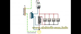
Before connecting the voltage relay, you will need to carefully study the typical electrical cabinet diagram. When installing it, the voltage relay must be installed after the electric meter in the gap in the phase wire; sometimes an RCD is placed between them, connected as necessary. With this arrangement, the surge protection device will cut off exactly the “phase”.
For normal operation, phase and ground are supplied to its input terminals simultaneously.
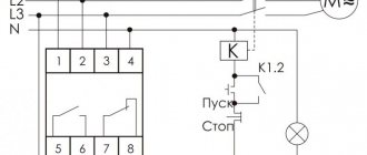
There are two schemes for connecting single-phase and three-phase relays to the consumption line:
- with direct load through the RLV;
- with consumer connection via a contactor included in the magnetic starter.
In each of these cases, it is possible to connect several devices in parallel, each of which can be connected to its own group of consumers.
When installing electrical panels in an apartment or private house, a connection diagram with a direct load through an RKN is most often used.
Relay contacts.
Depending on the design features, the intermediate relay contacts are normally open
(closing),
normally closed
(breaking) or
changeover
.
3.1. Normally open contacts.
As long as the supply voltage is not applied to the relay coil, its normally open contacts are always open
.
When voltage is applied, the relay is activated and its contacts close
, completing the electrical circuit. The pictures below show the operation of a normally open contact.
3.2. Normally closed contacts.
Normally closed contacts work the other way around: as long as the relay is de-energized, they are always closed
.
When voltage is applied, the relay is activated and its contacts open
, breaking the electrical circuit. The pictures show the operation of a normally open contact.
3.3. Changeover contacts.
For changeover contacts with a de-energized coil, the average
the contact attached to the anchor is
common
and closed with one of the fixed contacts. When the relay is triggered, the middle contact, together with the armature, moves towards the other fixed contact and closes with it, while simultaneously breaking the connection with the first fixed contact. The pictures below show the operation of a changeover contact.
Many relays have not one, but several contact groups, which makes it possible to control several electrical circuits simultaneously.
There are special requirements for intermediate relay contacts. They must have low contact resistance, high wear resistance, low tendency to weld, high electrical conductivity and long service life.
During operation, the contacts with their current-carrying surfaces are pressed against each other with a certain force created by the return spring. The current-carrying surface of a contact in contact with the current-carrying surface of another contact is called the contact surface
, and the place where the current passes from one contact surface to another is called
electrical contact
.
The contact of two surfaces does not occur over the entire apparent area, but only in separate areas, since even with the most careful treatment of the contact surface, microscopic tubercles and roughness will still remain on it. Therefore, the total contact area
will depend on the material, the quality of the contact surfaces and the compression force. The figure shows the contact surfaces of the upper and lower contacts in a greatly enlarged view.
At the point where current passes from one contact to another, electrical resistance occurs, which is called contact resistance
. The magnitude of the contact resistance is significantly influenced by the magnitude of the contact pressure, as well as the resistance of the oxide and sulfide films covering the contacts, since they are poor conductors.
During long-term operation, the contact surfaces wear out and can become covered with soot deposits, oxide films, dust, and non-conducting particles. Contact wear can also be caused by mechanical, chemical and electrical factors.
Mechanical wear occurs when contact surfaces slide and impact. However, the main cause of contact destruction is electrical discharges
, arising when opening and closing circuits, especially DC circuits with an inductive load. At the moment of opening and closing, the phenomena of melting, evaporation and softening of the contact material, as well as the transfer of metal from one contact to another, occur on the contact surfaces.
Silver, alloys of hard and refractory metals (tungsten, rhenium, molybdenum) and metal-ceramic compositions are used as materials for relay contacts. The most widely used material is silver, which has low contact resistance, high electrical conductivity, good technological properties and relatively low cost.
It should be remembered that there are no absolutely reliable contacts, therefore, to increase their reliability, parallel and serial connection of contacts is used: when connected in series, the contacts can break a large current, and parallel connection increases the reliability of the electrical circuit.
Recommendations for selection
From the above it follows that there are many types of voltage control relays. The selection is carried out taking into account the specific situation in which the RN will have to work. The most significant criteria for choosing a voltage monitoring relay are:
- Single-phase or three-phase network. An option is practiced when instead of one three-phase relay, 3 single-phase ones are installed.
- Relay type. Plug-in, designed for 1-3 consumers. They can withstand current up to 16 A. Modifications for DIN rail are more powerful. Through them it is possible to connect the entire apartment. The current passed is 40-80 A.
- Permissible relay current. For an ordinary apartment, a device capable of passing 30-40 A is suitable. This current is greater than the cross-section of household wiring will allow, but it is better to take the LV with a power reserve of 1.5-2 times. This way the device will last much longer.
- If a relay is purchased to connect a single household appliance, then before purchasing you should find out what its current consumption is. In this situation, it is enough to make a reserve of 30-50%.
Additional Information. There are voltage monitoring relays equipped with a built-in ammeter. These devices allow you to monitor the current consumed by the apartment. They can be used to provide protection against short circuits or network overloads.
Why do power surges occur?
Various devices operating from the mains have limitations on voltage parameters. This even applies to incandescent lamps, although in order to cause them to burn out, a significant excess of the specified standards is required.
Reduced mains voltage, affecting, for example, a refrigerator, threatens an interturn short circuit and breakdown of the compressor. The increase negatively affects both the compressor and the electronic elements of the device, as a result they fail, and repairs cost a lot of money.
Again, even a wide range of voltage parameters does not mean that the device will operate during surges, for example, from 100 to 240 volts. This means its viability in a given period, subject to the stability of the power grid.
Generating electrical installations are designed with an automatic voltage stabilizer. In this case, the deviation from the norm, according to GOST 721 and GOST 21128, should not be more than 10% for a short-term network failure and more than 5% for a long-term one.
However, at least 7 main reasons of a natural, emergency, or man-made nature can provoke them:
- Worn electrical wiring in the house.
- Lack of stabilizers at the transformer substation.
- Overload of power consumption on the line.
- Emergency situation in transmission networks.
- Break on the neutral line.
- Bypassing metering devices by unscrupulous consumers.
- Natural factors.
The consumer is responsible for the operation of electrical appliances, proper distribution of the load on internal wiring and the condition of these networks. If a malfunction or emergency is detected, you must immediately call the special service.
You can measure the voltage using a special device, a multimeter (tester). If a deviation from the norm is detected higher than 10%, it is recommended to immediately contact the emergency service of the local power grid to identify the causes of power surges
System power grids are entirely the responsibility of electricity suppliers. One of their tasks is to monitor voltage deviations from the norm in a fixed area.
But despite the delineation of responsibilities, even with strict control, changes are quite common.
By identifying the culprit of power surges on the line, you can achieve justice and full compensation for damaged property or poor quality of services provided.
Switch classification and application
A relay is a reliable switching device, so it has become widespread in various fields. Often these switches are used in industrial equipment and household electrical appliances.
Each relay is designed to perform a particular task
According to areas of application, devices are divided into groups:
- monitoring the operation of electronic and electrical systems;
- equipment protection;
- process automation.
Switch location in the washing machine