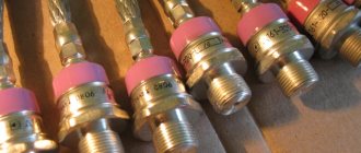
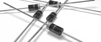
Power rectifier diodes of the D112 series are general-purpose pin diodes. Designed to convert direct and alternating current up to 25A (depending on the series) with a frequency of up to 500 Hz in circuits with a voltage of 100 V - 1600 V.
The polarity of the diode is determined by the icon on the case. With straight polarity, the base of the diode is the anode
, hard output -
cathode
.
When the polarity is reversed, it is the other way around, and the marking indicates the letter “X” - x.
Case type of diodes of the D112 series - SD1 : M5 thread, weight - 6 g. “SD” means “stud diode” - pin diode.
Diodes of the D112 series have the following standard ratings : D112-10, D112-10X, D112-16, D112-16X, D112-25, D112-25X.
To remove heat, diodes are assembled with coolers (radiators) using a threaded connection. To ensure reliable thermal and electrical contact of the diode with the cooler, the torque Md must be observed during assembly. Also, for better heat dissipation during assembly, heat-conducting paste KPT-8 can be used.
D112 power diodes are used as rectifying and demagnetizing diodes, to prevent the harmful effects of switching overvoltages, in low-voltage rectifiers for welding and galvanic equipment, in uncontrolled or semi-controlled rectifier bridges, as well as in electric generators for industry and transport.
Diodes are manufactured for use in temperate, cold (UHL) or tropical (T) climates; accommodation category – 2.
Detailed characteristics, labeling, dimensions, coolers used, installation and operation recommendations are listed below. The operation guarantee of the diodes supplied by our company is 2 years from the date of purchase, which is supported by relevant quality documents.
The final price for D112 series diodes depends on the class, quantity, delivery time and form of payment.
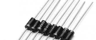
Good evening, my little LED lovers. Today I will teach you how to make the simplest voltage stabilizer for 12 volts in order to correctly power an LED strip in a car. And so, the list of necessary components: Microcircuit L7812 Capacitor 330 µF 16 volt Capacitor 100 µF 16 volt 1 ampere diode (1N4001, for example, or a similar Schottky diode) Wires 3 mm heat shrink
Here's a close-up of the microcircuit. We cut off her leg as in the photo.
Then add a little solder as in the photo.
Now we solder the capacitors and diode to the legs as in the photo. When soldering capacitors, take into account the polarity; the microcircuit has a minus in the middle.
Now we tin the wires and put heat shrink on the pluses.
Solder the wires as in the photo
And put on heat shrink. You can compress it with a lighter or a hairdryer. I myself use a soldering station hair dryer. Very comfortably.
Now we look at the location of the wires relative to the microcircuit. On the left is the power input, on the right is the output to the tape/light bulb.
We serve food and clap our hands.
At the input, my power supply produces 12.3 volts. The output is 11.10 volts. When the engine is running, the voltage in the on-board network is 13-16 volts, which provides 12 volts at the output.
Especially for those who only look at pictures and don’t read - before asking, look at the photos along with the text. Thanks to those who read to the end. There will be more interesting things later)
Read also: Chains for chainsaws types and sizes
By tradition, I invite everyone to my TAU tech community on VKontakte, where there is a lot of other interesting things)
The main purpose of rectifier diodes is voltage conversion. But this is not the only area of application for these semiconductor elements. They are installed in switching and control circuits, used in cascade generators, etc. Beginning radio amateurs will be interested in learning how these semiconductor elements are structured, as well as their operating principle. Let's start with the general characteristics.
What is a Schottky diode
The Schottky diode belongs to the family of diodes.
It looks almost the same as its brothers, but there are slight differences. A simple diode looks like this in the diagrams:
diode designation on the diagram
A zener diode is already designated as a diode with a “cap”
Zener diode designation in the diagram
The Schottky diode has two “caps”
Schottky diode designation in the diagram
To make it easier to remember, you can add a head and legs and imagine a little man dancing a lambada)
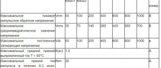
Schottky diode reverse voltage
So, as you remember, a diode allows electric current to pass in only one direction, and in the other direction it blocks the passage of electric current to some critical value, called diode reverse voltage .
This value can be found in the datasheet
diode reverse voltage
It is different for each brand of diode
If this value is exceeded, a breakdown will occur and the diode will fail.
Voltage drop across a Schottky diode
If you apply direct current to the diode, then the voltage will “settle” on the diode. This voltage drop is called the forward voltage drop of the diode. In datasheets it is designated as Vf, that is, Voltage drop .
forward voltage drop across the diode
If you pass direct current through such a diode, then the power that will be dissipated by it will be determined by the formula:
Where
P—power, W
Vf - forward voltage drop across the diode, V
I is the current through the diode, A
Therefore, one of the main advantages of a Schottky diode is that its forward voltage drop is much lower than that of a simple diode. Consequently, it will dissipate less heat, or in simple terms, heat up less.
Let's look at one example. Let's take a 1N4007 diode. Its forward voltage drop is 0.83 Volts, which is typical for a simple semiconductor diode.
voltage drop across the diode in direct connection
At the moment, a current of 0.5 A is passing through it. Let's calculate its power dissipation at the moment. P=0.83 x 0.5 = 0.415 W.
If we look at this case through a thermal imager, we can see that its body temperature was 54.4 degrees Celsius.
Now let's do the same experiment with a 1N5817 Schottky diode. As you can see, its forward voltage drop was approximately 0.35V.
voltage drop across the Schottky diode when connected directly
When a current of 0.5 A passes through a Schottky diode, we get a power dissipation of P = 0.5 x 0.35 = 0.175 W. At the same time, the thermal imager will show us that the body temperature will already be 38.2 degrees.
Consequently, Schottky is much more efficient than a simple semiconductor diode in terms of passing forward current through itself, since it has a lower voltage drop, and therefore dissipates less heat into the surrounding space and heats up less.
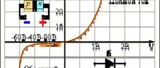
The forward voltage drop can also be viewed in datasheets. For example, the forward voltage drop across a 1N5817 Schottky diode can be found from a graph of forward current versus voltage drop across a Schottky diode
graph of forward current versus voltage
In our case, if we follow the graph-analytical method, we just get a value of 0.35 V
Device and design features
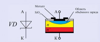
The main structural element is a semiconductor. This is a wafer of silicon or germanium crystal, which has two regions of p and n conductivity. Because of this design feature, it is called planar.
When manufacturing a semiconductor, the crystal is processed as follows: to obtain a p-type surface, it is treated with molten phosphorus, and for a p-type surface, it is treated with boron, indium or aluminum. During heat treatment, diffusion of these materials and the crystal occurs. As a result, a region with a p-n junction is formed between two surfaces with different electrical conductivities. The semiconductor obtained in this way is installed in the housing. This protects the crystal from external influences and promotes heat dissipation.
- Low-current rectifier diodes, they are used in circuits with a current of no more than 0.3 A. The housing of such devices is usually made of plastic. Their distinctive features are light weight and small dimensions.
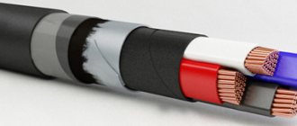
Low Power Rectifier Diodes - Devices designed for average power can operate with current in the range of 0.3-10 A. Such elements, for the most part, are made of metal housing and equipped with rigid leads. On one of them, namely on the cathode, there is a thread that allows you to securely fix the diode on the radiator used for heat removal.
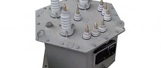
Medium power rectifier diode - Power semiconductor elements, they are designed for direct current over 10 A. Such devices are produced in metal-ceramic or metal-glass housings of the pin type (A in Fig. 4) or tablet type (B).
Rice. 4. High power rectifier diodes
Read also: How to install a circulation pump without welding
Schottky diode in RF circuits
Schottky diodes also have fast switching speed. This means we can use them in high frequency (RF) circuits.
So, let's take a frequency generator and set the sine frequency to 60 Hz
Let's take a 1N4007 diode and a 1N5817 Schottky diode. Let's connect them using a simple half-wave rectifier circuit
and we will take evidence from them
As you can see, both of them do an excellent job of rectifying the signal at a frequency of 60 Hz.
But what happens if we increase the frequency to 300 kHz?
Wow! The Schottky diode more or less copes with its task, which cannot be said about a simple 1N4007 diode. A simple diode cannot cope with its task of not allowing reverse current to pass through, so we see a negative surge on the oscillogram
From this we can conclude: Schottky diodes are recommended for use in RF circuits.
Replacement
Despite the prevalence of this model, a situation may arise in which the required diode is not in the home storage room. In this case, you should resort to searching for an alternative. There will be no problems with this, since there are components that are fully compatible or similar in characteristics.
Domestic analogues 1n4007
The ideal replacement option is the KD 258D; its characteristics are almost identical to the imported model, and in some respects it even surpasses it.
KD 258D is an almost complete analogue of 1N4007
Despite the obvious advantages of the domestic analogue, it has a significant drawback - high cost (compared to 1N4007). The original costs about $0.05, while our part costs about $1. Agree, the difference is significant.
In some cases, you can use diodes D226, KD208-209, KD243 and KD105, but you will first need to analyze their characteristics for compatibility with the operating mode in a particular device.
Foreign analogues
Among imported parts there is a wider choice for a full replacement; the following models can be cited as an example:
- HEPR0056RT, manufactured by Motorola;
- among Thompson products there are two complete analogues: BYW27-1000 and BY156;
- for Philips it is BYW43;
- and three components (10D4, 1N2070, 1N3549) from Diotec Semiconductor.
Reverse leakage current
But since Schottky diodes are so cool, why not use them everywhere? Why do we still use simple diodes?
If we connect the diode in the opposite direction, it will block the passage of electric current. This is true, but not entirely. Very little current will still flow through the diode. In some cases this is not taken into account. This small current is called reverse leakage current . In English it sounds like reverse leakage current .
It is very small, but it exists.
Let's do a simple experiment. Let's take a laboratory power supply, set it to 19 V and apply this voltage to the diode in the opposite direction
We measure the leakage current
diode reverse leakage current
As you can see, its value is 0.1 µA.
Let's now repeat the same experiment with a Schottky diode
Schottky diode reverse leakage current
Wow, almost 20 µA already! Well, yes, in some cases these are mere pennies and can be ignored. But there are circuits where such a small current is still unacceptable. For example, in peak detector circuits
peak detector circuit
In this case, these 20 µA will be quite significant.
But there is also another stumbling block. As the temperature increases, the reverse leakage current increases significantly!
dependence of the reverse leakage current on the body temperature of the Schottky diode
Therefore, you cannot use Schottky everywhere in the circuits.
But that's not all. The reverse voltage for Schottky diodes is several times less than for simple rectifier diodes. This can also be seen from the datasheet. If the reverse voltage is 1000V for the 1N4007 diode
Then for a 1N5817 Schottky diode this reverse voltage will already be only 20 V
Therefore, if this voltage exceeds the value described in the datasheet, we will end up with:
Installation
To install elements in the D0-41 housing, a pinout mounting diagram is used, and both horizontal and vertical positions of the part (relative to the printed circuit board) are allowed. Soldering should be done with “soft” (low-temperature) solder with a melting point of less than 210-220°C, for example, POS-61. The process should take no more than 10 seconds to prevent the element from overheating.
Note that the datasheet indicates a threshold temperature of 260°C, but, as practice shows, in this case it is better to play it safe than to spoil the part and waste time on soldering it back.
Diodes in the D0-215 package, like all SMD elements, are installed using the surface mount method, using special solder paste for this purpose.