NTMI type transformer is equipment capable of converting and measuring alternating electric current on a large scale for the operation of protection, alarms and other similar equipment. The unit allows you to monitor the condition of the insulating layers in the network. To choose the right instrument transformers, it is necessary to consider the technical characteristics and commissioning features.
Device
Transformer type NTMI 6 (10) kV is applicable for changing voltage levels and metering electricity in the network. Used in systems with isolated class neutral. Users ask when purchasing whether grounding is required for the presented structures. The device passport gives a clear answer. Neutral and grounding are required in automatic networks. The transformer connection diagram and unit maintenance are presented by the manufacturer in the instructions.
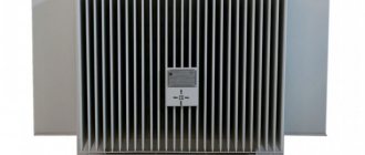
The transformer container is a metal structure. The lid is equipped with hooks that allow you to transport and install the device in a designated area. The structure has an oil plug at the bottom. The ground bolt is installed here. At the top of the unit there are HV and LV outputs. The hole for topping up the oil cooler is located here and is closed with a plug.
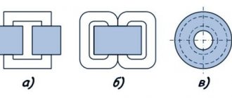
The transformer of category NTMI 10 (6) kV is equipped with a steel core. The coil circuit is copper.
Technical characteristics of the transformer NTMI-6, NTMI-10
| Transformer | Rated voltage of windings, kV | Rated voltage, kA in accuracy class | Maximum power limit | N, mm | Weight, kg | ||||
| VN | NN (main) | NN (additional) | 0,5 | 1,0 | 3,0 | ||||
| STMI-6 | 6 | 0.1 | 0.1/3 | 75 | 150 | 300 | 630 | 400 | 67 |
| NTMI-10 | 10 | 0.1 | 0.1/3 | 150 | 300 | 500 | 1000 | 490 | 87 |
Assembly and commissioning
The voltage transformer of the NTMI 10 (6) kV group has different dimensions and weight (according to the power). The cost also differs according to the specified characteristics. Assembly is carried out according to the manufacturer's instructions. The windings must be fixed to the rods of the magnetic drive, and a yoke is mounted. Electrical switching is carried out in accordance with existing standards. The drying procedure is in progress.
The active part is installed in the tank. The quality of the connection of the windings is controlled while the unit is not under voltage. The transformation coefficient and the error in the angular shift of the phase vectors are estimated. A voltage transformer of category NTMI 6 (10) kV must be thoroughly dried. Connections are checked. The lid is placed in the designated place and oil is poured into the tank.
The coolant level is monitored. The quality of the oil meets the requirements of the standards. Additional accessories are installed.
STMI design
The NTMI transformer tank is welded, round in shape. The assembly is lifted using brackets located on the transformer cover. At the bottom there is a plug for draining the oil, a plug for filling oil and taking an oil sample, and a grounding bolt. On the tank cover there are high voltage (HV), low voltage (LV) inputs, and a plug for adding oil. To ensure tightness, oil-resistant rubber is used. Transformers NTMI-6, NTMI-10 are filled with transformer oil having a breakdown voltage of at least 40 kV.
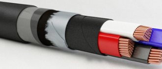
The active part consists of a magnetic core made of cold-rolled electrical steel, windings, HV and LV taps. The windings of transformers NTMI-6, NTMI-10 are made of copper wires. HV and LV bushings for outdoor installation, removable, porcelain feed-through insulators.
The assembly of NTM transformers is carried out carefully and accurately in accordance with the design documentation. The windings are installed and secured to the corresponding magnetic cores, after which the yoke is installed, electrical connections and drying under vacuum are carried out. Before installing the active part in the NTMI transformer tank, the connection of the windings, the transformation ratio and the angular error of the phase vector shift are checked.
After thorough drying and checking the tightening torques of the bolted connections, the active part is installed in the transformer tank, the transformer cover is attached and filled with oil.
Diagram and dimensions of the transformer NTMI-6-66
Overall dimensions of NTMI-6
Tests
All NTM transformers are subject to standard and acceptance tests in accordance with GOST 11677 and regulatory documentation.
Users sometimes ask when purchasing whether grounding is required for the presented structures. The device data sheet gives a clear answer. In automatic networks, neutral and grounding are required. The connection diagram for the STMI transformer and maintenance of the unit are presented by the manufacturer in the instructions.
Design and connection of voltage transformer NTMI-6
Transformers NTMI 10
Transformers NTMI-6, NTMI-10
Designation
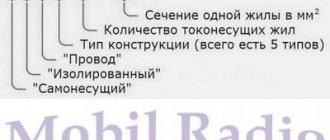
Units of the presented type are designated according to the installed system. Marking allows you to identify the features of the equipment. Operating personnel must see a sign indicating the type of equipment. The decoding of the data is as follows: NTMI-6(10) – UZ (TZ).
- N - voltage transformer.
- T - three-phase.
- M – oil type system cooler, natural circulation.
- And - measuring, an additional winding of the KIZ type is provided.
- 6(10) – parameters of the HV terminal winding, kV.
- UZ (TZ) is a type of climatic placement.
The information is printed on a special plate, which is attached with screws to the transformer housing. The marking must be placed in a visible place.
for “Transformers NTMI-6, NTMI-10”
- Sergey M
:V
NTMI-6 burned out, is it possible to replace it with NTMI-10 and how will this affect electricity metering (current costs 2xTOL)
Answer
- Elik
:
V
At the meter inputs, instead of 100 V there will be 60 V and there will be an undercount of electricity
Answer
- Petr Sidorov
:
V
Is there a scheme for connecting STMI 10 to a 6 kV network?
Answer
- Sergey M
:
V
When the AXC windings are switched on to a linear voltage of 6 kV, in each secondary winding a-0, c-0 we get 60V, in-0, respectively, 0 Volt, and in the meter it is also necessary to enter 60V in v-0. If you turn on a 3-element counter as a 2-element counter, then 100V must be supplied to a-0 and c-0. In general, nothing works out. I come to the conclusion that it is impossible to use a 10 kV VT in a 6 kV circuit for metering.
Answer
- Valdemar
:
V
1. not 60 V, but 100 V (connection circuit “not full star” or 2TN) 2. you can take into account the correction factor “6/10” BUT: it’s not “it doesn’t work”, it’s “impossible” - the documentation for NTMI-10 is not provides for such a connection
Answer
- Grandpa Pak
:
V
There is a transformer NTMI-6 and NTMI-10 with non-working coils. Please tell me, who has experience, is it really possible to rewind them?
Answer
- Ze's high
:
V
This is too hemorrhoidal a matter, I have never heard of or encountered the repair of VT windings. The wires (HV winding) are very thin and there are too many turns.
Answer
- Vakha
:
V
Ekrny babay. So it's scrapped? But who is winding them in the first place?
Answer
- Zhorik
:
V
NTMI is no longer produced, NAMI-6(10) is produced at a plant in Ramenskoye or Samara.
Answer
Features of operation
Installations of the presented category are operated strictly in accordance with generally recognized standards. Commissioning and monitoring of equipment condition is carried out by trained, experienced employees.
The presented equipment is installed in areas with moderate and cold climates. It is prohibited to store fire hazardous, explosive, chemical substances, gases, or liquids nearby.
The unit is installed at an altitude of no more than 1 km above sea level. The design is not designed to withstand vibration, mechanical shock or shaking. The work cycle is quite long. The equipment is turned off for scheduled repairs and maintenance. If signs of malfunction appear, in an emergency situation, the power is immediately turned off.
The ambient temperature can reach from +40 to -45ºС for category U1. Climatic modification HL1 allows operation in the range from +40 to -60ºС. Relative humidity is 80%. The above conditions contribute to long-term, efficient operation of the equipment.
Having considered the features, operating principles and designations of STMI transformers, you can choose the right device that meets the needs of consumers.
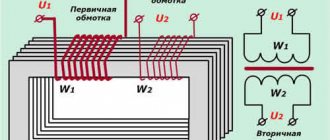
Operating principle of TN
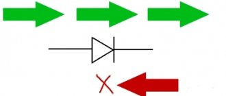
The operating principle of a voltage transformer is similar to that of a current transformer. Let's define this again. An alternating current passes through the primary winding, this current forms a magnetic flux. The magnetic flux penetrates the magnetic circuit and the HV and LV windings. If a load is connected to the secondary winding, then a current begins to flow through it, which arises due to the action of the EMF. EMF is induced due to the action of magnetic flux. By selecting different numbers of turns of the primary and secondary windings, you can obtain the desired output voltage. This is shown in more detail in the article about the vector diagram of a voltage transformer.
If a constant voltage is applied to the VT, then the EMF is not created by the constant magnetic flux. Therefore, VTs are produced for alternating voltage. The transformation ratio of a voltage transformer is naturally called the ratio of the voltage of the primary winding to the voltage of the secondary and is written as a fraction. For example, 6000/100. When young students come, they sometimes answer the question of what coefficient is 60. You shouldn’t do that.
ads
Friends, I greet you all! Please help with clarifications! I am a young RES dispatcher, I have questions about the operation of TN-10 and TN-110. I'll start with TN-10: 2 PS 35/10, one per post. opera current, the second on AC, KRUN version, with BBTEL vacuum tubes and Sirius. The following question arose: when one of the outgoing lines is shorted to ground (exactly), the TN signals ground. But before it was established that there was a short circuit on the line, a flurry of accusations began regarding the malfunction of the transformer itself. When PC 10 burns out on a VT, I know what the voltmeter readings are, in this case it was clear to me personally that it was not a PC. Those who went to the VT don’t really know much about the readings of voltmeters. I fell for their lead and decided to check the voltage of the secondary circuits of the VT. I'm on a shift at the RDP, the OVB at the substation is measured at 100V AP from the VT in the VT cell. They give me the following readings: 100, 100, 02. Well, those who went to TN (beginning of OTG) of course were delighted and already started calling USP. What helped me save myself from shame was the decision to turn off one of the lines; I guessed right, the earth was gone. Then they found that the arrester was damaged. in general, this is a story that made me delve into the secondary circuits of the TN-10. Hence the question: 1- in normal mode, without a ground fault, I myself went to the substation on my day off and measured the voltage at the AP. Relative to the housing of KRUN 100, 100, 60. Relative to the ShP in the relay compartment of KRUN TN-10: 60,60,100. Phase-to-phase on AP: 60,100,60. What the heck? why such indications? I thought there should be 100V everywhere. Explain to me how from where and why? 2- The chief engineer of the Distribution Zone tells me that when there is a ground fault, the phase that closes does not reach the voltage transformer, i.e. briefly: when the ground is on the line, on phase B, then if you measure the secondary on the TN, on the AP TN-10, there will be no phase B either. As far as I know, the secondary circuits of the TN-10 are powered by the automatic transfer switches, on-load tap-changers, and emergency valves, some of our Siriuses directly receive power from the TN-10... This is what happens, according to the logic of Ch. Eng. In the event of a ground fault, can half of the automation be left without voltage? Here I remember from monitoring the voltage circuits in the TN-110 circuits, and I know for sure that in the event of a fault, one phase in the TN-110 circuits, protection ShDE-2802, TNZNP are automatically removed. In short, I'm at a loss. 3- the most important question is when the PC in front of the VT burns out - I know what the voltmeter will show, but HERE’S HOW TO UNDERSTAND EXACTLY! when TN-10 is covered, how to determine this? by what signs, direct or indirect, or how to accurately or indirectly determine that it is DEFINITELY not TN-10???? For starters, this is enough, I will be very grateful to all competent people for their help! p.s. sorry if there is gram in the text. errors.
General information
Voltage transformers, as a rule, are a type of transformer that are designed not to transmit power, but to galvanically separate the high-voltage side from the low-voltage side.
Such transformers are designed to power measuring and control devices. On the “high” side of various voltage transformers, naturally, the voltage can be different, it can be 6000, 35,000 volts and even much more, but on the “low” side (on the secondary winding) it does not exceed 100 volts.
This is very convenient for unifying control devices. If you make measuring and control devices, and these are mainly relays, for high voltage, then, firstly, they will be very large, and secondly, very dangerous to maintain.
The transformation ratio is indicated on the transformer itself and can look like Ku = 6000/100, or simply 35000/100. Dividing one number by another, we get in the first case this coefficient is 60, in the second 350.
These transformers are available as “dry” transformers, in which electrical cardboard is used as insulation. They are usually used for voltages up to 1000 volts. Example NOS-0.5. Where, H means voltage, meaning a voltage transformer, O - single-phase, C - dry, 0.5 - 500 volts (0.5 kV). And also oil ones: NTMI, NOM, 3NOM, NTMK, in which oil plays the role of both an insulator and a cooler. And cast, to be precise, with cast insulation (3NOL - three-winding single-phase voltage transformer with cast insulation), in which all windings and the magnetic circuit are filled with epoxy resin.
Connection diagrams for voltage transformer windings
The simplest way to measure phase-to-phase voltage is to connect a single-phase two-winding voltage transformer according to the diagram shown in the figure on the left.
In this case, at the ends of the secondary winding we have a voltage corresponding to the interphase BC, but reduced taking into account the transformation ratio.
All three phase-to-phase voltages can be measured using two single-phase transformers connected in a certain way.
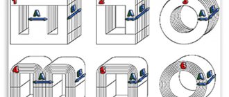
In three-phase transformers, the primary windings are always connected in a star configuration.
The secondary windings can be connected either in a star or delta configuration.
With the top connection at the output points of the secondary winding, we have the ability to measure phase-to-phase voltages. With a lower connection, according to the so-called open delta circuit, we can detect the fact of a short circuit or wire break in one of the phases on the high side. The terminals are marked 01 and 02, since under normal operating conditions there is no voltage between these points.
To connect the protection relays, as mentioned above, additional windings in three-winding voltage transformers are used. Here is an example of connecting such transformers to a three-phase network. In this case, the ends of the windings are grounded in both the primary and secondary windings.
Here are a few more options for connecting single-phase transformers for measuring phase-to-phase and phase-to-phase voltages, as well as for powering control equipment.
More complex options for connecting voltage transformers containing a larger number of windings are studied in a special electrical engineering course.
Write comments, additions to the article, maybe I missed something. Take a look at the site map, I will be glad if you find anything else useful on my site.