The marking of capacitors is of great importance for the correct selection of a particular element in various circuits. Compared to resistors, it is quite complex and varied. Particular difficulties arise when reading the markings on the housings of small capacitors due to the small surface area. A qualified specialist who constantly uses these devices in his work must confidently read the product labeling and decipher it correctly.
Rules for marking capacitors of constant capacity
When assembling homemade electronic circuits, you are inevitably faced with the selection of the necessary capacitors.
Moreover, to assemble the device, you can use capacitors that have already been used and have worked for some time in electronic equipment.
Naturally, before reuse, it is necessary to check capacitors, especially electrolytic ones, which are more susceptible to aging.
When selecting capacitors of constant capacity, it is necessary to understand the markings of these radio elements, otherwise, if there is an error, the assembled device will either refuse to work correctly or will not work at all. The question arises, how to read the capacitor markings?
A capacitor has several important parameters that should be taken into account when using them.
The first is the nominal capacitance of the capacitor . It is measured in fractions of Farad.
The second is permission. Or in other words, the permissible deviation of the nominal capacity from the specified one. This parameter is rarely taken into account, since household radio equipment uses radio elements with a tolerance of up to ±20%, and sometimes more. It all depends on the purpose of the device and the features of a particular device. This parameter is usually not indicated on circuit diagrams.
The third thing that is indicated in the marking is the permissible operating voltage . This is a very important parameter and you should pay attention to it if the capacitor will be used in high-voltage circuits.
So, let's figure out how capacitors are marked.
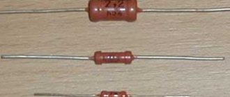
Some of the most popular capacitors that can be used are constant capacitors K73 - 17, K73 - 44, K78 - 2, ceramic KM-5, KM-6 and the like. Analogues of these capacitors are also used in imported electronic equipment. Their labeling differs from domestic ones.
Domestic-made capacitors K73-17 are polyethylene terephthalate film protected capacitors. The housing of these capacitors is marked with an alphanumeric index, for example 100nJ, 330nK, 220nM, 39nJ, 2n2M.
K73 series capacitors and their markings
Labeling rules.
Capacitances from 100 pF to 0.1 μF are marked in nanofarads, indicating the letter H or n .
The designation 100 n is the value of the nominal capacity. For 100n – 100 nanofarads (nF) – 0.1 microfarads (uF). Thus, a capacitor with index 100n has a capacity of 0.1 μF. Similar for other notations. For example: 330n – 0.33 µF, 10n – 0.01 µF. For 2n2 – 0.0022 µF or 2200 picofarads (2200 pF).
You can find markings like 47 H C. This entry corresponds to 47 n K and is 47 nanofarads or 0.047 μF. Similar to 22NS - 0.022 µF.
In order to easily determine the capacity, you need to know the designations of the main submultiple units - milli, micro, nano, pico and their numerical values. Read more about this here.
Also in the marking of K73 capacitors there are such designations as M47C, M10C. Here, the letter M conventionally stands for microfarad. The value 47 comes after M, i.e. the nominal capacitance is a fraction of a microfarad, i.e. 0.47 µF. For M10C - 0.1 µF. It turns out that capacitors marked M10C and 100nJ have the same capacity. The only differences are in the recording.
Thus, capacitance from 0.1 μF and above is indicated with the letter M , m instead of a decimal point, the insignificant zero is omitted.
The nominal capacity of domestic capacitors up to 100 pF is indicated in picofarads, placing the letter P or p after the number. If the capacitance is less than 10 pF, then put the letter R and two numbers. For example, 1R5 = 1.5 pF.
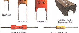
On ceramic capacitors (type KM5, KM6), which are small in size, usually only a numerical code is indicated. Here, look at the photo.
Ceramic capacitors with capacitance marked with a numerical code
For example, the numeric marking 224 corresponds to a value of 22,0000 picofarads, or 220 nanofarads and 0.22 µF. In this case, 22 is the numerical value of the denomination value. The number 4 indicates the number of zeros. The resulting number is the capacitance value in picofarads. Writing 221 means 220 pF, and writing 220 means 22 pF. If the marking uses a four-digit code, then the first three digits are the numerical value of the denomination value, and the last, fourth, is the number of zeros. So at 4722, the capacitance is 47200 pF - 47.2 nF. I think we've sorted this out.
The permissible deviation of the capacity is marked either with a percentage number (±5%, 10%, 20%) or with a Latin letter. Sometimes you can find the old tolerance designation encoded with a Russian letter. The permissible deviation of capacitance is similar to the tolerance for the resistance value of resistors.
Letter code of capacity deviation (tolerance).
So, if a capacitor with the following marking is M47C, then its capacity is 0.047 μF, and the tolerance is ±10% (according to the old marking with a Russian letter). It is quite difficult to find a capacitor with a tolerance of ±0.25% (as marked with a Latin letter) in household equipment, which is why a value with a larger error was chosen. Mainly in household equipment, capacitors with tolerance H , M , J , K . of the nominal capacity, like this 22n K , 220n M , 470n J.
Table for deciphering the conditional letter code of the permissible deviation of the capacity.
| Tolerance in % | B letter designation | |
| lat. | rus. | |
| ±0.05p | A | |
| ±0.1p | B | AND |
| ±0.25p | C | U |
| ±0.5p | D | D |
| ± 1,0 | F | R |
| ± 2,0 | G | L |
| ± 2,5 | H | |
| ± 5,0 | J | AND |
| ± 10 | K | WITH |
| ± 15 | L | |
| ± 20 | M | IN |
| ± 30 | N | F |
| -0. +100 | P | |
| -10. +30 | Q | |
| ± 22 | S | |
| -0. +50 | T | |
| -0. +75 | U | E |
| -10. +100 | W | YU |
| -20. +5 | Y | B |
| -20. +80 | Z | A |
Marking of capacitors by operating voltage.
An important parameter of the capacitor is also the permissible operating voltage. It should be taken into account when assembling homemade electronics and repairing household radio equipment. For example, when repairing compact fluorescent lamps, it is necessary to select a capacitor for the appropriate voltage when replacing failed ones. It would be a good idea to take a capacitor with a margin of operating voltage.
Typically, the value of the permissible operating voltage is indicated after the rated capacity and tolerance. It is designated in volts with the letter B (old marking) and V (new). For example, like this: 250V, 400V, 1600V, 200V. In some cases, the V is omitted.
Sometimes Latin letter coding is used. To decipher, you should use the table of letter coding of the operating voltage.
| N rated operating voltage, V | B letter code |
| 1,0 | I |
| 1,6 | R |
| 2,5 | M |
| 3,2 | A |
| 4,0 | C |
| 6,3 | B |
| 10 | D |
| 16 | E |
| 20 | F |
| 25 | G |
| 32 | H |
| 40 | S |
| 50 | J |
| 63 | K |
| 80 | L |
| 100 | N |
| 125 | P |
| 160 | Q |
| 200 | Z |
| 250 | W |
| 315 | X |
| 350 | T |
| 400 | Y |
| 450 | U |
| 500 | V |
Thus, we learned how to determine the capacitance of a capacitor by marking, and along the way we became acquainted with its main parameters.
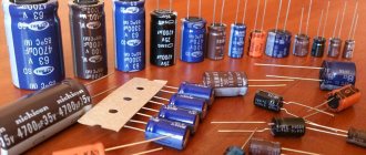
Film capacitors with polyethylene terephthalate dielectric
The listed advantages are largely explained by design features. The modifications of capacitors under consideration are created using a dielectric made from a polymer film. To reduce the inductive properties, instead of a roll, complex layer formation with pressing is used. In fact, a plurality of plate energy storage devices are created, connected in parallel.
The main advantage of this type of dielectric is its ability to self-recover. After an electrical breakdown, the created conductor gradually evaporates. The process is accelerated by the passage of current through the corresponding section of the structure, which is accompanied by heating of the corresponding area. Quite quickly without additional actions, the functional characteristics of the capacitor are normalized.
For comparison with other dielectrics, you can study the information presented below.
Capacitor parameters
| Characteristics | Dielectric type | ||
| Polyethylene terephthalate | Polypropylene | Polystyrene | |
| Loss tangent | 0,01-0,1 | 0,002 | 0,0001-0,0015 |
| Insulation resistance, MOhm | 10 000 | 50 000 | 100 000 |
| Absorption coefficient, % | 0,2-0,8 | Less than 0.5 | Less than 0.1 |
| TKE (temperature coefficient), 10-6/°C | -200 to 400 | -200 to 100 | -200 |
When choosing a polyethylene terephthalate product, you can use high structural strength and good dielectric constants. However, the relatively small loss tangent and limited insulating properties should be taken into account.
At the project preparation stage, the operating parameters of the capacitor and compliance with the conditions of future operation are comprehensively checked. To eliminate errors, it is recommended to study expert reviews of products from certain manufacturers. When choosing a supplier (store), costs and official warranty obligations are assessed.
Code marking of the capacity of imported capacitors
According to IEC standards, in practice there are four ways to encode the nominal capacity.
1. 3-digit encoding
The first two digits indicate the capacitance value in picofarads (pf), the last two digits indicate the number of zeros. When the capacitor has a capacitance of less than 10 pF, the last digit may be "9". For capacitances less than 1.0 pF, the first digit is “0”. The letter R is used as a decimal point. For example, code 010 is 1.0 pF, code 0R5 is 0.5 pF.
* Sometimes the last zero is not indicated.
2. 4-digit encoding
4-digit coding options are possible. But even in this case, the last digit indicates the number of zeros, and the first three indicate the capacity in picofarads (pF).
3. Capacitance marking in microfarads
The letter R may be used instead of the decimal point.
4. Mixed alphanumeric marking of capacity, tolerance, TKE, operating voltage
Unlike the first three parameters, which are marked in accordance with standards, the operating voltage has different alphanumeric markings from different companies.
Source: rcl-radio.ru
Capacitive values
Capacitor 104 whose capacitance is considered to be 10*104 will have a C value equal to 100,000 pF or 0.1 μF. To answer the question, how many picofarads is a 100n capacitor, you need to know the multiplicity and fraction of mathematical prefixes. To do this, you can look at the table or use an online value translator.
Table of multiple and fractional prefixes
The ability to decipher the coding of ceramic capacitors allows you to select a similar part, replace a faulty one, or use the one you need when assembling a circuit. Designations on the case such as 104, 100n, 108j and other alphanumeric marks will no longer be able to mislead anyone.
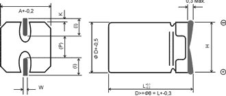
How are large capacitors marked?
To correctly read the technical specifications of a device, some preparation is necessary. You need to start studying with units of measurement. To determine capacitance, a special unit is used - farad (F). The value of one farad for a standard circuit seems too large, so household capacitors are marked in smaller units. The most commonly used is mF = 1 µF (microfarad), which is 10 -6 farads.
In calculations, an off-label unit can be used - millifarad (1mF), which has a value of 10 -3 farads. In addition, designations can be in nanofarads (nF) equal to 10 -9 F and picofarads (pF) equal to 10 -12 F.
Capacitance markings for large capacitors are applied directly to the housing. In some designs, the markings may differ, but in general, you need to be guided by the units of measurement mentioned above.
Designations are sometimes written in capital letters, for example, MF, which actually corresponds to mF - microfarads. The marking fd is also found - an abbreviated English word farad. Therefore mmfd will correspond to mmf or picofarad. In addition, there are designations that include a number and one letter. This marking looks like 400m and is used for small capacitors.
In some cases, it is possible to apply tolerances, which are an acceptable deviation from the rated capacitance of the capacitor. This information is of great importance when, when assembling certain types of electrical circuits, capacitors with precise capacitance values may be required. If we take the marking 6000uF + 50%/-70% as an example, then the maximum capacitance value will be 6000 + (6000 x 0.5) = 9000 uF, and the minimum 1800 uF = 6000 - (6000 x 0.7).
If there are no percentages, you need to find the letter. Usually it is located separately or after the numeric designation of the container. Each letter corresponds to a specific tolerance value. After this, you can begin to determine the rated voltage.
With large capacitor housing sizes, voltage markings are indicated by numbers followed by letters or letter combinations in the form V, VDC, WV or VDCW. The WV symbols correspond to the English phrase WorkingVoltage, which means operating voltage. Digital readings are considered to be the maximum permissible capacitor voltage, measured in volts.
If there is no voltage marking on the device body, such a capacitor should only be used in low-voltage circuits. In an AC circuit, use a device designed specifically for this purpose. Capacitors designed for direct current cannot be used without the ability to convert the rated voltage.
The next step is to identify the positive and negative symbols that indicate the presence of polarity. Determining the positive and negative is of great importance, since incorrect determination of the poles can lead to a short circuit and even explosion of the capacitor. In the absence of special markings, the device can be connected to any terminals, regardless of polarity.
The pole designation is sometimes applied in the form of a colored stripe or a ring-shaped indentation. This marking corresponds to the negative contact in electrolytic aluminum capacitors, which are shaped like a tin can. In very small tantalum capacitors, these same symbols indicate positive contact. If there are plus and minus symbols, the color coding can be ignored.
Some notes and tips on working with capacitors
It must be remembered that capacitors with a higher rated voltage should be selected as the ambient temperature increases, creating a larger voltage reserve to ensure high reliability. If the maximum constant operating voltage of the capacitor is specified, this refers to the maximum temperature (unless otherwise stated). Therefore, capacitors always operate with a certain margin of safety. And yet, it is desirable to ensure that their actual operating voltage is at a level of 0.5-0.6 nominal.
If a limit value for alternating voltage is specified for a capacitor, then this applies to a frequency of (50-60) Hz. For higher frequencies or in the case of pulsed signals, the operating voltages should be further reduced to avoid overheating of the devices due to dielectric losses. High-capacity capacitors with low leakage currents are able to retain the accumulated charge for a long time after the equipment is turned off. To ensure faster discharge, for greater safety, you should connect a resistor with a resistance of 1 MOhm (0.5 W) in parallel with the capacitor.
Explanation of capacitor markings
To decipher the marking, you need the meaning of the first two digits indicating the capacity. If the capacitor has very small dimensions that do not allow the capacity to be marked, it is marked according to the EIA standard, which is used for all modern products.
Designation of numbers
If the designation contains only two numbers and one letter, in this case the digital values correspond to the capacity of the device. All other markings are deciphered in their own way, in accordance with one design or another.
The third digit in the designation is a multiplier of zero. In this case, decryption is performed depending on the number located at the end. If such a digit is in the range 0-6, then a certain number of zeros are added to the first two digits. For example, you can take the marking 453, which will be deciphered as 45 x 10 3 = 45000.
When the last digit is 8, the first two digits are multiplied by 0.01. Thus, when labeled 458, the result is 45 x 0.01 = 0.45. If the 3rd digit is 9, then the first two digits must be multiplied by 0.1. As a result, the notation 459 is converted to 45 x 0.1 = 4.5.
After determining the capacity, you need to determine the unit to measure it. The smallest capacitors - ceramic, film and tantalum - have a capacitance measured in picofarads (pF), amounting to 10 -12. To measure the capacitance of large capacitors, microfarads (μF) equal to 10 -6 are used. Units of measurement can be designated by letters: p – picofarad, u – microfarad, n – nanofarad.
Letter designation
After the numbers, it is necessary to decipher the letters included in the marking. If a letter is present in the first two characters, it can be decrypted in several ways. If the letter R is present, it is replaced by a comma, which is used for the decimal fraction. Decoding the 4R1 marking will look like 4.1 pF.
If there are letters p, n, u, corresponding to pico-, nano- and microfarads, a decimal point is also replaced. The n61 designation reads 0.61 nF, the 5u2 marking corresponds to 5.2 μF.
Marking of ceramic capacitors
Ceramic capacitors have a flat round shape and two contacts. On the case, in addition to the main indicators, the tolerance for deviations from the nominal capacity is indicated. For this purpose, a specific letter is used, placed immediately after the digital designation of the container. For example, the letter “B” corresponds to a deviation of + 0.1 pF, “C” - + 0.25 pF, D - + 0.5 pF. These values apply for capacitances less than 10 pF. For capacitors with a capacitance of more than 10 pF, the letter designations correspond to a certain percentage of deviations.
Mixed alphanumeric markings
The tolerance marking may consist of an alphanumeric designation according to the “letter-number-letter” scheme. The first letter character corresponds to the minimum temperature, for example, Z = 10 degrees, Y = -30 0 C, X = -55 0 C. The second numeric character is the maximum temperature.
The numbers correspond to the following indicators: 2 – 45 0 C, 4 – 65 0 C, 5 – 85 0 C, 6 – 105 0 C, 7 – 125 0 C. The value of the third letter symbol means the changing capacitance of the capacitor, within the range between minimum and maximum temperature. More accurate indicators include “A” with a value of + 1.0%, and less accurate indicators include “V” with a value from 22 to 82%. The most commonly used "R" is 15%.
Some notes and tips on working with capacitors
It must be remembered that capacitors with a higher rated voltage should be selected as the ambient temperature increases, creating a larger voltage reserve to ensure high reliability. If the maximum constant operating voltage of the capacitor is specified, this refers to the maximum temperature (unless otherwise stated). Therefore, capacitors always operate with a certain margin of safety. And yet, it is desirable to ensure that their actual operating voltage is at a level of 0.5-0.6 nominal.
If a limit value for alternating voltage is specified for a capacitor, then this applies to a frequency of (50-60) Hz. For higher frequencies or in the case of pulsed signals, the operating voltages should be further reduced to avoid overheating of the devices due to dielectric losses. High-capacity capacitors with low leakage currents are able to retain the accumulated charge for a long time after the equipment is turned off. To ensure faster discharge, for greater safety, you should connect a resistor with a resistance of 1 MOhm (0.5 W) in parallel with the capacitor.
Other markings
The markings on the capacitor body allow you to determine the voltage value. The figure shows special symbols that correspond to the maximum permissible voltage for a particular device. In this case, parameters are given for capacitors that can only be operated at constant current.
In some cases, marking capacitors is greatly simplified. For this purpose, only the first digit is used. For example, zero will mean a voltage below 10 volts, a value of 1 - from 10 to 99 volts, 2 - from 100 to 999 V, and so on, according to the same principle.
Other markings apply to capacitors that were manufactured much earlier or intended for special purposes. In such cases, it is recommended to use special reference books to avoid serious mistakes when assembling the electrical circuit.
Source: electric-220.ru
Construction of ceramic capacitors
Initially, this element consisted of two plates, between which an air gap was maintained. Subsequently, this gap began to be filled with various dielectrics.
Ceramic part design
Important! By changing the size of the plates (the area of the plates) and experimenting with the composition and structure of the dielectric, we varied the main property of a two-terminal network - capacitance (C). Capacitors are sometimes simply called capacitance
In diagrams, a similar element is denoted by two parallel vertical segments with a distance between them. This visually resembles two plates and an air gap.
Capacity image on diagrams
Ceramic capacitors belong to the class of elements with a solid dielectric of inorganic origin. In this case it is ceramics. The structure of the 104k capacitor is as follows:
- ceramic disk acting as a dielectric;
- two layers of silver, which are applied to the disc by sputtering on both sides;
- terminals for connection.
Ceramic disk two-terminal devices have a stable linear dependence of C on temperature. Their connection circuit does not depend on the polarity of the applied voltage, which is why they are called non-polar.
Attention! A capacitor is a storage device (battery) for energy that it collects while charging, and can release it at the right moment, discharging it to the load. A capacitive two-terminal network does not allow direct current to pass through, but does not prevent the passage of alternating current.
Elements with one dielectric gap are called single-layer. The small size of disk ceramic containers, according to their electrical characteristics, does not allow a charge to accumulate on the plates, the effect of which can be checked by touching two of its terminals with your hand at the same time. However, parts with a large capacity (several thousand microfarads) can, when discharged through a person’s body, cause him an electric shock.
Ceramic disc elementsHow to decipher the markings of a capacitor and find out its capacity?
Basic information about the characteristics of capacitors, which are components of almost all electronic circuits, is usually placed on their cases. Depending on the standard size of the element, manufacturer, production time, the data applied to the electronic device constantly changes not only in composition, but also in appearance.
With a decrease in the size of the case, the composition of alphanumeric designations was changed, encoded, and replaced by color markings. The variety of internal standards used by manufacturers of radio-electronic elements requires certain knowledge to correctly interpret the information printed on an electronic device.
Capacitor positive symbol
On domestic Soviet products, only the positive contact was indicated with a “+” sign. This sign was applied to the case next to the positive terminal. Sometimes in the literature the positive terminal of electrolytic capacitors is called the anode, since they not only passively accumulate charge, but are also used to filter alternating current, i.e. have the properties of an active semiconductor device. In some cases, the “+” sign is also placed on the printed circuit board, close to the positive terminal of the drive placed on it.
On products of the K50-16 series, polarity markings are applied to the bottom, made of plastic. Other models in the K50 series, such as the K50-6, have a plus sign painted on the bottom of the aluminum case, next to the positive terminal. Sometimes imported products produced in the countries of the former socialist camp are also marked on the bottom. Modern domestic products meet global standards.
The marking of SMD (Surface Mounted Device) capacitors intended for surface mounting (SMT - Surface Mount Technology) differs from ordinary ones. Flat models have a black or brown body in the form of a small rectangular plate, part of which at the positive terminal is painted over with a silver stripe with a plus sign on it.
Why is labeling needed?
The purpose of marking electronic components is to allow them to be accurately identified. Capacitor markings include:
- data on the capacitance of the capacitor - the main characteristic of the element;
- information about the rated voltage at which the device remains operational;
- data on the temperature coefficient of the capacitance, which characterizes the process of changing the capacitance of the capacitor depending on changes in ambient temperature;
- percentage of permissible deviation of the capacity from the nominal value indicated on the device body;
- release date.
For capacitors, when connecting which polarity must be observed, information must be provided that allows the element to be correctly oriented in the electronic circuit.
The marking system for capacitors produced at enterprises that were part of the USSR had fundamental differences from the marking system used at that time by foreign companies.
Characteristics and properties
Capacitor parameters that are used to create and repair electronic devices include:
- Capacity - C. Determines the amount of charge that the device holds. The value of the nominal capacity is indicated on the case. To create the required values, the elements are included in the circuit in parallel or in series. Operational values do not coincide with calculated values.
- Resonant frequency - fр. If the current frequency is greater than the resonant one, then the inductive properties of the element appear. This makes work difficult. To ensure the design power in the circuit, it is reasonable to use a capacitor at frequencies below resonant values.
- Rated voltage - Un. To prevent breakdown of the element, the operating voltage is set less than the rated voltage. The parameter is indicated on the capacitor body.
- Polarity. If the connection is incorrect, breakdown and failure will occur.
- Electrical insulation resistance - Rd. Determines the leakage current of the device. In devices, parts are located close to each other. At high leakage current, parasitic connections in the circuits are possible. This leads to malfunctions. Leakage current worsens the capacitive properties of the element.
- Temperature coefficient - TKE. The value determines how the capacitance of the device changes with fluctuations in ambient temperature. The parameter is used when developing devices for operation in harsh climatic conditions.
- Parasitic piezoelectric effect. Some types of capacitors create noise in devices when deformed.
Marking of domestic capacitors
All post-Soviet enterprises are characterized by fairly complete labeling of radioelements, allowing for minor differences in designations.
The first and most important parameter of a capacitor is capacitance. In this regard, the value of this characteristic is placed in first place and is encoded with an alphanumeric designation. Since the unit of measurement of capacitance is the farad, the letter designation contains either the symbol of the Cyrillic alphabet “F” or the symbol of the Latin alphabet “F”.
Since the farad is a large value, and the elements used in industry have much smaller values, the units of measurement have a variety of diminutive prefixes (mili-, micro-, nano- and pico). Letters of the Greek alphabet are also used to designate them.
- 1 millifarad is equal to 10 -3 farads and is denoted 1mF or 1mF.
- 1 microfarad is equal to 10 -6 farads and is designated 1 µF or 1F.
- 1 nanofarad is equal to 10 -9 farads and is denoted 1nF or 1nF.
- 1 picofarad is equal to 10 -12 farads and is denoted 1pF or 1pF.
If the capacity value is expressed as a fraction, then the letter indicating the dimension of the units of measurement is placed in place of the comma. Thus, the designation 4n7 should be read as 4.7 nanofarads or 4700 picofarads, and the inscription like n47 corresponds to a capacity of 0.47 nanofarads or 470 picofarads.
In the case where the capacitor does not have a rating indicated, the integer value indicates that the capacitance is indicated in picofarads, for example, 1000, and the value expressed as a decimal fraction indicates the rating in microfarads, for example, 0.01.
The capacitance of the capacitor indicated on the case rarely corresponds to the actual parameter and deviates from the nominal value within a certain range. The exact capacitance value sought when making capacitors depends on the materials used to manufacture them. The spread of parameters can range from thousandths to tens of percent.
The value of the permissible deviation of the capacitance is indicated on the capacitor body after the nominal value by placing a letter of the Latin or Russian alphabet. For example, the Latin letter J (Russian letter I in the old designation) indicates a deviation range of 5% in one direction or another, and the letter M (Russian V) - 20%.
Such a parameter as the temperature coefficient of capacitance is included in the marking quite rarely and is applied mainly to small-sized elements used in electrical circuits of timing circuits. For identification, either an alphanumeric or color notation system is used.
There is also a combination of letter and color markings. Its options are so diverse that to accurately determine the value of this parameter for each specific type of capacitor, you need to refer to GOSTs or reference books on the corresponding radio components.
Rated voltage
The voltage at which the capacitor will operate for a specified service life while maintaining its characteristics is called the rated voltage. For capacitors of sufficient size, this parameter is applied directly to the body of the element, where the numbers indicate the rated voltage value, and the letters indicate in which units of measurement it is expressed.
For example, the designation 160V or 160V indicates that the nominal voltage is 160 volts. Higher voltages are indicated in kilovolts - kV. On small-sized capacitors, the rated voltage is encoded with one of the letters of the Latin alphabet. For example, the letter I represents a nominal voltage of 1 volt, and the letter Q represents 160 volts.
Date of issue
According to “GOST 30668-2000 Electronic products. Marking”, letters and numbers indicating the year and month of production are indicated.
“4.2.4 When indicating the year and month, first indicate the year of manufacture (the last two digits of the year), then the month - in two digits. If the month is indicated by one digit, then a zero is placed in front of it. For example: 9509 (1995, September).
4.2.5 For products whose overall dimensions do not allow the year and month of manufacture to be indicated in accordance with 4.2.4, the codes given in tables 1 and 2 should be used. The marking codes given in table 1 are repeated every 20 years.”
The date when a particular production was carried out can be displayed not only in the form of numbers, but also in the form of letters. Each year has a relationship with a letter from the Latin alphabet. The months from January to September are designated by numbers from one to nine. The month of October has a relationship with the number zero. November corresponds to the Latin letter N, and December – D.
| Year | Code |
| 1990 | A |
| 1991 | B |
| 1992 | C |
| 1993 | D |
| 1994 | E |
| 1995 | F |
| 1996 | H |
| 1997 | I |
| 1998 | K |
| 1999 | L |
| 2000 | M |
| 2001 | N |
| 2002 | P |
| 2003 | R |
| 2004 | S |
| 2005 | T |
| 2006 | U |
| 2007 | V |
| 2008 | W |
| 2009 | X |
| 2010 | A |
| 2011 | B |
| 2012 | C |
| 2013 | D |
| 2014 | E |
| 2015 | F |
| 2016 | H |
| 2017 | I |
| 2018 | K |
| 2019 | L |
Location of markings on the body
Labeling plays an important role on any product. It is often placed on the first line on the case and has a capacity value. The same line involves placing the so-called tolerance value on it. If both applications do not fit on this line, then this can be done on the next one.
A similar system is used to apply film-type condensates. The arrangement of elements must be located according to certain regulations, which are produced by GOST or TU for an element of an individual type.
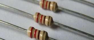
Color marking of domestic radioelements
In the production of lines with so-called automatic types of installation, color application appeared, as well as its direct significance in the entire system.
Today, the most commonly used application is using four colors. In this case, we resorted to using four stripes. So, the first strip together with the second represents the capacitance value in so-called picofarads. The third band indicates the deviation that can be allowed. And the fourth band, in turn, means the voltage of the nominal type.
We give you an example of how this or that element is designated - capacity - 23 * 106 picofarads (24 F), permissible deviation from the nominal value - ± 5%, rated voltage - 57 V.
Alphanumeric designation
If you disassemble old Soviet equipment, then everything will be quite simple - on the cases it says “22pF”, which means 22 picofarads, or “1000 uF”, which means 1000 microfarads. Old Soviet capacitors were usually large enough to allow such “long texts” to be written on them.
Global, so to speak, alphanumeric marking involves the use of letters of the Latin alphabet:
- p – picofarads,
- n – nanofarads
- m – microfarads.
At the same time, it is useful to remember that if we conventionally take picofarad as a unit of capacity (although this is not entirely correct), then the letter “p” will denote units, the letter “n” – thousands, the letter “m” – millions. In this case, the letter will be used as a decimal point. Here is a clear example, a capacitor with a capacity of 2200 pF, according to this system will be designated 2n2, which literally means “2.2 nanofarads”. Or a capacitor with a capacity of 0.47 µF will be designated m47, that is, “0.47 microfarads”.
It will be interesting➡ A few facts about electrolytic capacitors
Moreover, domestically produced capacitors have similar markings in Cyrillic, that is, picofarads are designated by the letter “P”, nanofarads by the letter “N”, microfarads by the letter “M”. But the principle is the same: 2H2 is 2.2 nanofarads, M47 is 0.47 microfarads. For some types of miniature capacitors, “μF” is designated by the letter R, which is also used as a decimal point, for example:
1R5 =1.5 µF.
Marking of imported capacitors
To date, the standards that have been adopted from the IEC apply not only to foreign types of equipment, but also to domestic ones. This system involves applying a code type marking to the product body, which consists of three direct numbers.
The two numbers that are located from the very beginning indicate the capacity of the item and in units such as picofarads. The number that is located third in order is the number of zeros. Let's look at this using the example of 555 - that's 5,500,000 picofarads. In the event that the capacity of the product is less than one picofarad, then the number zero is indicated from the very beginning.
There is also a three-digit type of encoding. This type of application is used exclusively for parts that are highly precise.
Color coding of imported capacitors
The designation of names on an object such as a capacitor has the same production principle as on resistors. The first stripes on two rows indicate the capacity of this device in the same measurement units. The third stripe has a designation indicating the number of immediate zeros. But at the same time, the blue color is completely absent; blue is used instead.
It is important to know that if the colors are the same in a row, then it is advisable to create gaps between them so that it is clearly understood. Indeed, in another case, these stripes will merge into one.
Features of the use of capacitor 2A 104 J
Capacitor energy
Good consumer parameters make it possible to use radio components of this category to solve various engineering problems. Capacitors are used in low-voltage circuits to create high-quality noise suppression filters. When preparing design calculations, the following advantageous features can be taken into account:
- minimal parasitic inductance;
- significant discharge current;
- reliability;
- long-term preservation of original operating parameters under difficult operating conditions.
When considering analogues, attention should be paid to the relatively high temperature dependence. Ceramic capacitors do not have a large enough capacity for their comparative dimensions.
Marking of smd components
So-called SMD components are used for surface mounting and are extremely small in size. Accordingly, for this reason, they are marked with minimal dimensions. As a result, there is a system for abbreviating both numbers and letters. The letter designates the capacity of a particular object in units of picofarads. As for the number, it denotes the so-called multiplier to the tenth power.
Very common electrolytic capacitors can have values of the main type of parameter on their immediate body. This value is a fraction in decimal type.
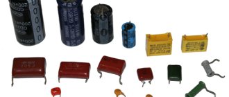
What types of capacitors are there?
- Made from paper or metal - suitable for both high- and low-frequency circuits. Due to their low mechanical strength, their “filling” is placed in a metal body;
- Electrolytic - their dielectric is a thin layer of metal oxide that is formed as a result of electrochemical manipulation. Almost all types of these elements are polarized, therefore they function only in those circuits where there is a constant voltage and polarity is observed. If polarity reversal occurs, an irreversible chemical reaction occurs inside the element, which can lead to its destruction. Since gas is released inside, the product may even explode;
- Polymer - polymer dielectric eliminates swelling and loss of charge of capacitors. The polymer is characterized by its physical parameters, so the product has the following advantages: high pulse current, low equivalent resistance, stable temperature coefficient even at low temperatures;
- Film - the dielectric here is a plastic film. They have many advantages: they are able to function at high currents, are tensile-resistant and are characterized by minimal leakage current. The following types of plastic are used: polyester, polycarbonate, polypropylene. Recently, polyphenylene sulfide has been increasingly used;
- Ceramic - such products have different properties and coding. Only materials made from ceramics have a wide range of relative electrical permeability values (counting in tens of thousands). High permeability allows the production of elements of compact size but high capacity. Moreover, they are able to function in any polarization and are characterized by small leaks. Device parameters depend on temperature, voltage and frequency;
- With an air dielectric - the dielectric of devices is air. Their feature is excellent performance at high frequencies. For this reason, they are often installed as variable capacitors.
There are different types of devices