A diode usually refers to vacuum or semiconductor devices that pass alternating electric current in only one direction and have two contacts for inclusion in an electrical circuit. One-way conductivity of a diode is its main property. This property determines the purpose of the diode:
- conversion of high-frequency modulated oscillations into audio frequency currents (detection);
- rectification of alternating current into direct current.
Detection also means signal detection.
Classification of diodes
Based on the source semiconductor material, diodes are divided into four groups:
- germanium,
- silicon,
- from gallium arsenide,
- from indium phosphide.
Germanium diodes are widely used in transistor receivers, as they have a higher transmission coefficient than silicon diodes .
This is due to their greater conductivity at a low voltage (about 0.1...0.2 V) of the high frequency signal at the detector input and a relatively low load resistance (5...30 kOhm).
According to their design and technological characteristics, diodes are distinguished:
- point,
- planar.
According to their purpose, semiconductor diodes are divided into the following main groups:
- rectifying,
- universal,
- impulse,
- varicaps,
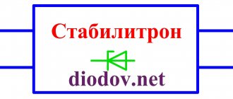
- Zener diodes (reference diodes),
- stabilizers,
- tunnel diodes,
- reverse diodes,
- avalanche-span (ALD),
- thyristors,
- photodiodes, s
- LEDs and optocouplers.
Diodes are characterized by the following basic electrical parameters :
- current passing through the diode in the forward direction (direct current Ipr);
- current passing through the diode in the opposite direction (reverse current Irev);
- the highest permissible rectified CURRENT Ivypr.max;
- the highest permissible direct current Ipr.add.;
- direct voltage Unp;
- reverse voltage IOBR;
- highest permissible reverse voltage iobr.max
- capacitance CD between the diode terminals;
- dimensions and operating temperature range.
Video
How to determine the polarity of a capacitor
Coffee capsule Nescafe Dolce Gusto Cappuccino, 3 packs of 16 capsules
1305 ₽ More details
Coffee capsules Nescafe Dolce Gusto Cappuccino, 8 servings (16 capsules)
435 ₽ More details
Cases for iPhone 11 Pro Max
Old notation system
In accordance with the notation system developed before 1964, the abbreviated designation for diodes consisted of two or three elements .
The first element is letter, D - diode.
The second element is a number corresponding to the type of diode: 1...100 - point germanium, 101...200 - point silicon, 201...300 - planar silicon, 801...900 - zener diodes, 901...950 - varicaps, 1001...1100 - rectifier columns. The third element is a letter indicating the type of device. This element may be missing if there are no diode varieties.
Currently, there is a notation system corresponding to GOST 10862-72. In the new, as in the old system, the following division into groups according to the maximum (limiting) frequency of amplification (current transmission) is accepted into:
- low-frequency LF (up to 3 MHz),
- midrange frequency (from 3 to 30 MHz),
- high frequency HF (over 30 MHz),
- ultra-high frequency microwaves;
By power dissipation:
- low-power (up to 0.3 W),
- average power (from 0.3 to 1.5 W),
- high (over 1.5 W) power.
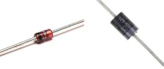
Color coding
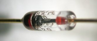
Every radio amateur knows the difficulty of identifying diodes surrounded by a glass housing. One person. Sometimes the manufacturer bothers to apply clear marks and multi-colored rings. According to the notation system, three characteristics are introduced:
- Markers of cathode and anode areas.
- The color of the body, replaced by a colored dot.
According to the state of affairs, at first glance we can distinguish the types of diodes:
- The D9 family is marked with one or two colored rings in the anode area.
- KD102 diodes in the anode area are indicated by a colored dot. The case is transparent.
- KD103 have a color body that complements the dot, with the exception of 2D103A, which is indicated by a white dot in the anode area.
- The KD226, 243 families are marked with a cathode region ring. No other marks are provided.
- Two colored rings in the cathode area can be seen in the KD247 family.
- KD410 diodes are indicated by a dot in the anode area.
Other visible marks are present. You will find a more detailed classification by studying the publication of A.P. Kashkarov. On the labeling of radioelements. Beginners are concerned about the issue of determining the location of the cathode and anode.
- You see: one side of the cylinder is equipped with a dark stripe - a cathode has been found. Colored may be part of the labeling discussed today.
- If you know how to operate a multimeter, the anode is easy to find. An electrode where we will apply the red probe to open the valve (we will hear a bell).
- The new diode is equipped with an anode antenna that is longer than the cathode.
- Let's look through the glass body of the LED with a magnifying glass: the metal anode resembles the tip of a spear, smaller in size than the cathode.
- Old diodes contained arrow markings. The tip is the cathode. Allows you to determine the direction of activation visually. Modern radio installers have to train their intelligence, visual acuity, and precision of manipulation.
Foreign products received a different designation system. When choosing an analogue, use special correspondence tables. For the rest, the import base differs little from the domestic one. Marking is carried out according to JEDEC standards (USA), European system (PRO ELECTRON). Colorful color code decoding tables are massively provided by online sources.
Color coding
New notation system
The new diode marking system is more advanced. It consists of four elements.
The first element (letter or number) indicates the source semiconductor material from which the diode is made: G or 1 - germanium * K or 2 - silicon, A or 3 - gallium arsenide, I or 4 - indium phosphide.
The second element is a letter indicating the class or group of the diode.
The third element is a number that determines the purpose or electrical properties of the diode.
The fourth element indicates the serial number of the technological development of the diode and is designated from A to Z.
For example:
- diode KD202A stands for: K - material, silicon, D - rectifier diode, 202 - purpose and development number, A - variety;
- 2C920 - high power silicon zener diode of type A variety;
- AI301B is a gallium arsenide tunnel diode of the switching type B.
Sometimes there are diodes designated according to outdated systems: DG-Ts21, D7A, D226B, D18. D7 diodes differ from DG-Ts diodes in their all-metal housing design, as a result of which they operate more reliably in a humid atmosphere.
Germanium diodes of the DG-Ts21...DG-Ts27 type and diodes D7A...D7Zh, which are similar in characteristics, are usually used in rectifiers to power radio equipment from an alternating current network.
The diode designation does not always include some technical data, so you need to look for them in reference books on semiconductor devices.
One of the exceptions is the designation for some diodes with the letters KS or a number instead of K (for example, 2C) - silicon zener diodes and stabilistors.
After these designations there are three digits, if these are the first digits: 1 or 4, then taking the last two digits and dividing them by 10 we get the stabilization voltage Ust.
For example:
- KS107A - stabistor, Ust = 0.7 V,
- 2S133A - zener diode, Ust = 3.3 V.
If the first digit is 2 or 5, then the last two digits show Ust, for example:
- KS 213B - Ust = 13 V,
- 2C 291A - Ust = 91 V.
If the number is 6, then you need to add 100 V to the last two digits, for example: KS 680A - Ust = 180 V.
General characteristics and operating principle
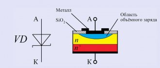
Rectifier diodes are capable of making and breaking circuits, as well as switching electrical signals. Their operating principle is based on certain features of the pn junction. The bottom line is that each diode has two leads or electrodes. One of them is the anode, and the second is the cathode. The anode is connected to the p-layer, and the cathode is adjacent to the n-layer.
Between the p- and n-layer there is a small region without mobile charge carriers, which has high electrical resistance. This is called the barrier layer and defines the potential barrier.
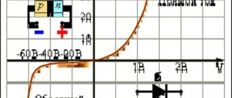
When an external voltage is applied to the pn junction, creating an electric field directed opposite to the field of the blocking layer, then this layer begins to decrease in thickness. It finally disappears at a voltage of 0.4–0.6 Volts. In this case, the current, which is called direct, increases significantly.
Applying external power of a different polarity leads to an increase in the blocking layer and an increase in the resistance of the pn junction. In this case, the current is created by minority charge carriers. It will have an insignificant value even at a relatively high voltage.
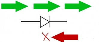
Consequently, the forward current is created by the majority charge carriers, and the reverse current is created by the minority charge carriers. Rectifier diodes pass direct (positive) electric current in the direction from the anode to the cathode.
How a rectifier diode works is most easily explained using a simple half-wave rectifier circuit.
The diode half-wave rectifier remains in the open position during the positive half-cycle, so current passes through it and enters the load. During the negative half-cycle, the diode is turned off and no voltage is supplied to the load. As a result, the output receives pulses that consist only of positive half-cycles and are called direct current.
Where is it used in practice?
With the development of scientific and technological progress, the use of rectifier diodes has become a necessity. They are used in such units and mechanisms as:
- Power supplies for engines of land, water and air vehicles, industrial machines, drilling rigs.
- Diode bridges for welding machines.
- Rectifier installations for galvanic baths.
- Installations for air and water purification.
- High voltage transmission lines.
Rectifier circuits are divided into single-phase and multiphase, half-wave and full-wave. The simplest full-wave circuit can be built on the basis of two half-wave circuits. In such a rectifier circuit there are two diodes and one resistor. If you use not two, but four diodes, then the efficiency will increase significantly.
The quality of the rectifier is reflected by the rectification factor. Its value is determined by the ratio of forward and reverse currents. The higher the coefficient, the better the rectifier does its job.
Diodes are used in practice not only as rectifiers, but also as detectors. It is very easy to construct working signal limiters from diode rectifiers. To do this, you need to connect two diodes in parallel. In this position, they will act as excellent and effective protection for the amplifier input. For example, this method is used for a microphone amplifier, as it helps to maximize the quality and level of the signal.
Diodes are integrated into logic devices, as well as walkie-talkies, baby monitors and other switches whose task is to transmit clear, uninterrupted remote signals.
LEDs are also in demand at the moment. A few decades ago they were used only as indicators inside various devices. Today, both simple devices such as hand-held flashlights and more complex equipment, such as LCD TVs, are equipped with LEDs.
To summarize, we can say that modern rectifier diodes are available in a wide range. They differ in both their design and performance characteristics. When choosing the right radio element, you should be guided by the data given in the reference manuals.