Good day to all! Most electronic circuits require constant current to operate properly. However, rectifier devices of various designs produce voltages that have a pulsating component. To reduce ripple, a smoothing filter is installed between the rectifier and the load. In modern circuits, the role of such a filter is played by a large-capacity electrolytic capacitor parallel to the load. In many cases it is quite sufficient, especially when powering digital circuits. But when powered by capacitive filters of analog devices or devices with high current consumption, impulse noise has a significant impact on the operation of the device, and in special cases, it disables it. Therefore, in addition to the capacitor, a choke is installed in series with the load, which significantly improves the operating mode of the device. This article is devoted to the calculation of anti-aliasing filter chokes.
To assemble a radio-electronic device, you can pre-make a DIY KIT kit using the link.
Is it possible to make a transformer from a choke?
It is possible to assemble a high-quality transformer from a choke with your own hands. A certain set of tools will be required, but high-end skills will not.
Radio amateurs often claim that it is impossible to assemble a vehicle from a choke due to lack of space for the secondary winding. But if you work carefully, it can be done. It is worth understanding that the transformer from the available chokes will not have high parameters and can be used in limited areas.
Calculation of the cross-section of the wires of the secondary winding of the transformer
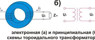
Diagram of a transformer with primary and secondary windings.
The voltage at the output of the welding machine transformer in the absence of a welding arc (idle mode) is usually 60-80 V. The higher the idle voltage, the more reliably the arc is ignited. The welding arc voltage is usually 1.8-2.5 times less than the no-load voltage.
Attention. It is necessary to constantly remember that in the absence of an arc the voltage at the transformer output is life-threatening.
For welding in everyday life, an electrode with a diameter of 3 mm is usually used, which is sufficient to provide an arc current of approximately 150 A. With an open circuit voltage of 70 V, the arc voltage will be approximately 25 V, and the power consumption P of the welding machine must be at least
Р=25×150=3750 W =3.75 kW.
It is advisable to design the transformer for higher power, that is, higher welding arc current. For example, with an arc current of 200 A, the power consumption will be approximately 5 kW. This is the power the transformer should be designed for.
The single-phase voltage in the house should be 220 V, but it can vary by ±22 V. This is one of the reasons why the arc current may change and will need to be adjusted.
The cross-section of the wire in the secondary winding of the transformer is determined based on the current density equal to 5 A/mm2. For a current of 200 A, the wire cross-section is 40 mm2, that is, it can only be a busbar that is wound with layer-by-layer insulation. Based on existing standard sizes, you can select the required tire both in length and cross-section.
Typical sizes of copper busbars produced by industry:
Manufacturing diagram of a welding choke
- length from 0.5 to 4 m with intervals of 0.5 m;
- width from 2 to 60 cm with intervals of 1 cm (with widths from 4 to 10 cm) and with intervals of 5 cm (with widths from 10 to 60 cm);
- thickness from 3 to 10 mm.
You can also use a stranded wire, the cross-section of which corresponds to the calculated value. To increase the cross-section, the wire can be folded in half or three. For aluminum wire, the cross-section must be increased by 1.6-1.7 times.
For a choke that is connected at the output of the transformer, the cross-section of the wire must be the same as in the secondary winding of the transformer.
Where is the invention used?
Devices made from lamp components do not have high power ratings. The maximum threshold is up to 20 watts. Switching power supplies are used. The main area of application is the design of a network power supply of the simplest type. The step-down type is used as a matching link between the amplifier input and the signal source. There are applications where a transformer and inductor are placed between two devices and amplifiers. There are also situations when low-frequency and step-down models act as a matching element between the vehicle load and the amplifier.
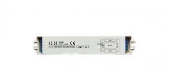
How to select an electromagnetic choke
When choosing an electromagnetic choke (ballast), pay attention to power.
When choosing an electromagnetic choke, pay attention to the following parameters:
- Operating voltage. Standard home networks require 220 - 240 V devices with a frequency of 50 Hz.
- Power. Must match the lamp power. If you need to connect two or more lamps, the power of the choke must correspond to the sum of their powers.
- Current. The permissible value is indicated in Amperes on the housing.
- Power factor. It is advisable to select devices with maximum parameter values. For electronic ballasts it usually does not exceed 0.5, so an additional capacitor is required.
- Working temperature. The range of ambient and throttle temperatures at which all elements remain operational.
- Energy efficiency. Determined by class in accordance with the accepted gradation. The average classes B1 and B2 are typical for EMPRAs.
- Capacitor parameters. The operating voltage and capacitance of the capacitor, which is connected in parallel to the supply network.
What is it: scheme of the invention
In terms of their principle of operation, the throttle and the step-down type of vehicle are similar. But visually they are easy to distinguish by the different number of windings. Only one is installed on the inductor, while on the transformer there are two or more. There is an opinion that the throttle has no clearance, but the vehicle does, or vice versa. This opinion is erroneous, since the constitutive features change depending on the resistance coefficients, therefore, the gap may be absent in both places.
The inductor transformer as an invention appeared recently. Radio amateurs noted that the first is a tool for accumulating a certain amount of energy component. In this case, inductance acts, which determines the efficiency of the device. An optimally assembled device from a choke does not serve as a source of energy storage. Its main purpose is to provide isolation for installed circuits, as well as bring voltage indicators to the required number. The function of a transformer, which is not present in the source material, is the conversion of resistances, the coordination of parameters.
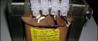
Sequencing
When the necessary tools and materials are prepared, you can begin to manufacture the throttle for welding. The algorithm of actions is as follows:
- disassemble the transformer, clean the coils from traces of old windings;
- make gaskets from fiberglass, cardboard impregnated with bakelite varnish, or other suitable dielectrics, which will subsequently play the role of an inductive (air) gap. They can simply be glued to the corresponding surfaces of the coils. The thickness of the gasket should be 0.8-1.0 mm;
- wind a thick copper or aluminum wire onto each coil. You should focus on a round wire made of aluminum with a cross-section of 36 mm or copper with a similar ohmic resistance. Each “horseshoe” is covered with 3 layers of 24 turns each;
- lay a dielectric material between the layers - fiberglass, cardboard impregnated with bakelite varnish or another dielectric. The gaskets must be reliable, since a choke of this design is prone to self-breakdown between windings. If the resistance between the windings is lower than the air resistance between the electrode and the additive, then a breakdown will occur between the windings, and the welding device will be irreversibly damaged.
Winding must be done evenly, without overlaps, strictly in the same direction, so that the “bridge” between the coils is on one side of the future inductor, and the input and output contacts are on the other.
In case of an error, the jumper can also be installed askew. It is important that its installation turns coils with different winding directions into coils with the same direction in fact.
Type of chokes
There is a wide range of fluorescent lamps on the market. And each type of fluorescent lamp has its own choke transformer. For example, a DRL lamp and a HPS lamp cannot be lit by the same type of throttle. It's all about different parameters for starting and maintaining combustion. Here the voltage and current are different.
But the MGL lamp can operate both from the choke of the DRL lamp and from the HPS. But there is one point. The brightness of this light source will depend on the applied voltage. And the color temperature will be different.
Attention! Any choke transformer will “outlast” several lamps in terms of its service life. Of course, with the caveat that the lamp is used correctly.
Varieties of chokes But you have to take into account the fact that the lamp “gets old” over the years. A special alkali metal paste is applied to the tungsten electrodes of fluorescent fluorescent lamps. So this paste gradually evaporates, the electrodes are exposed, and, therefore, the voltage increases, which leads to overheating of the inductor. The end result can be two options:
- The coil winding will break, which will cut off the voltage supply to the electrodes.
- The coil will short-circuit. And this is connecting the lamp directly to the AC mains. The lamp will burn out - that’s for sure, or it may explode, which will lead to damage to the lamp as a whole.
Therefore, my advice is not to wait for the lamp to burn out on its own. There is a special replacement schedule that is determined by the manufacturer, and which must be strictly adhered to. When carrying out preventive maintenance, experienced electricians must check these lighting devices for the voltage parameter. If it approaches the normal limit, then the lamp is changed before its service life. It is better to replace an inexpensive lamp than an expensive choke transformer.
Application area
Answering the question why a choke is needed, we can say with confidence that its main application is filters. No high-quality power source can do without this simple element. Its use allows you to get rid of voltage ripples, which cause instability in the operation of many devices - motherboards, video and sound cards, etc.
Smoothing the signal shape by eliminating its parasitic component ensures stable operation of microprocessor units, which are especially dependent on the quality of the voltage supplying them.
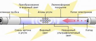
In addition, using the element’s ability to accumulate energy and then release it into a circuit, the inductor has found its application in fluorescent lamps. Such illuminators operate on the principle of an arc discharge maintained in inert gas vapor. In order for it to occur, a high starting voltage must appear between the electrodes, capable of breaking through the gas dielectric. Thanks to the choke, such a discharge is created.
They are also used in advanced lighting devices - induction lamps. The difference between such lamps and fluorescent lamps is the absence of electrodes necessary for ignition. Three components are used to produce light: electromagnetic induction, gas discharge, and phosphor glow.
It is worth noting another application of the choke - a welding transformer. Here the main purpose of the radio element is to stabilize the current. The welding choke installed in the inverter shifts the phase between current and voltage. This use simplifies ignition of the electrode and maintains a stable arc.
The ability of an element to create a magnetic field is often used in electromagnets with high power, as well as in various electromechanical relays, electric motors and even generators.
Testing the functionality of the device
During trial testing, the voltage provided by a single turn of the winding changes. The device is connected to the device and, based on the data received, the number of turns required for a certain indicator is calculated. During final assembly, the pins are soldered to the board.
A novice radio amateur can assemble a transformer from a choke. The only difficulty is that it is not possible to rid it of energy accumulation.
How to make a transformer from a choke is asked by radio amateurs when they need equipment that is simple in design. In fact, this new invention can be assembled with your own hands from existing materials and using standard tools. You will first need to study the circuit and technical features in order to assemble a device with the required parameters.
Filter choke with core gap
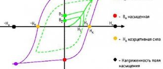
To reduce the drop in the magnetic permeability and inductance of the inductor with an increase in the bias current, a non-magnetic gap is introduced into the inductor core. Below are the magnetization curves of the core with and without gap.
Magnetization curves of the core material: without gap (1) and with gap (2).
As can be seen from the figure, the hysteresis loop of a core without a gap is line 1, and the hysteresis loop of a core with a non-magnetic gap is line 2. That is, curve 2 stretches and rotates relative to the zero coordinate. Thus, the inductor core, in the presence of a gap, the magnetization characteristic of which is linear, is saturated at relatively higher currents in the winding than the core without a gap.
From this we can conclude that when the bias current increases, it is necessary to select a larger non-magnetic gap to increase the inductance of the inductor.
The question arises of choosing the length of the non-magnetic gap in the core. In one of the articles I talked about how to calculate the equivalent magnetic permeability in the presence of a gap. Here the inverse problem is to calculate the length of the gap based on some given permeability, the expression will look like
where δ is the length of the non-magnetic gap, mm,
le – effective length of the magnetic field line, mm,
μe is the effective magnetic permeability of the core with a gap,
μr is the relative magnetic permeability of the core material. Since the value of the magnetic permeability of the core material is significantly greater than the required permeability μe << μr, the last term in the expression can be ignored.
The design of the throttle and its purpose using the example of a railway track
AC track circuits are installed on some sections of railways. In these (electrified) sections, the contact wire is the direct conductor of current to electric locomotives, and the return lines are the rail threads and the ground.
In the case when current is passed through both rail threads, the AC rail circuit being installed is called a two-thread one. In this case, the purpose of the inductor transformer is to pass the reverse traction current bypassing the insulating joints on each side. Each device has two windings: main and additional.
While the train is moving, current flows through both halves of the inductor transformer winding, then the currents collide at the midpoint and branch out again in the direction of the traction substation. Correct installation of devices ensures that traction current does not influence the equipment.
Physical processes in the inductor core
As already mentioned, a smoothing choke is a coil with a ferromagnetic core, which significantly increases the magnetic field, so all the characteristics of the choke are determined by the properties of the core. At the same time, the properties of the core depend on the current IL flowing through the inductor. This current can be represented as the sum of a constant component I0 and an alternating component I~.
Current flowing through the filter choke.
In this regard, two parameters of the pulsating current can be distinguished: the amplitude value of the current Imax and the effective value of the current I, which are determined by the following expressions
where I0 and I~ are, respectively, the amplitude of the constant and variable components of the pulse current flowing through the smoothing choke,
kf – coefficient of the current shape of the alternating component.
Let's consider the effect of pulsating current on the parameters of the core. The figure below shows the core magnetization curves for two modes: in the absence of magnetization (I0 = 0) and with direct current bias (I0 > 0).
Throttle operation during magnetization.
The figure shows curves of changes in the magnetic field induction in the core when it is magnetized by a sinusoidal current in two operating modes: without magnetization (curve 1) and with magnetization by direct current I0 (curve 2). As is known, when the core is periodically magnetized, the magnetic induction B changes not along the main magnetization curve, but along closed curves called magnetization reversal loops (highlighted in red). In the first case, when there is no bias, the loop is symmetrical with respect to the main magnetization curve (loop 1). In the case of the presence of bias current I0, the magnetization reversal of the core occurs along the so-called private magnetization reversal loops (loop 2). Partial magnetization reversal loops are characterized by an increased area, which means an increase in losses in the core (the area limited by the loop is equal to the power losses in the core).
In addition to the increase in losses when the core is saturated, there is a decrease in the magnetic permeability of the core material. Since the inductance of the inductor L has a direct dependence on the magnetic permeability, therefore there is a decrease in inductance.
The equivalent permeability of a substance μe is determined from the relationship between the induction B created by the magnetic field and the intensity H of a given magnetic field
where ω is the number of turns of wire in the winding,
I – current through the inductor.
The inductance of the inductor can be determined by the following expression
where ω is the number of turns of wire in the winding,
μ0 – magnetic constant, μ0 = 4π*10-7 H/m,
μе – equivalent (relative) magnetic permeability of the core,
Sе – equivalent cross-sectional area of the core,
lе – equivalent length of the magnetic line of the core.
lM – length of the magnetic line in the core.
Is it possible to make a transformer from a choke?
It is possible to assemble a high-quality transformer from a choke with your own hands. A certain set of tools will be required, but high-end skills will not.
Radio amateurs often claim that it is impossible to assemble a vehicle from a choke due to lack of space for the secondary winding. But if you work carefully, it can be done. It is worth understanding that the transformer from the available chokes will not have high parameters and can be used in limited areas.
Where is the invention used?
Devices made from lamp components do not have high power ratings. The maximum threshold is up to 20 watts. Switching power supplies are used. The main area of application is the design of a network power supply of the simplest type. The step-down type is used as a matching link between the amplifier input and the signal source. There are applications where a transformer and inductor are placed between two devices and amplifiers. There are also situations when low-frequency and step-down models act as a matching element between the vehicle load and the amplifier.
Step-by-step scheme of work execution
The remodeling does not take much time, but it will require care. First, the source element is prepared. It is desoldered from the ballast of the electronic circuit, board. It turns out a small cube, which is torn to a w-shaped core. In the latter, two equivalent parts are installed, they are tightly fastened to each other. These devices, which are identical in size and visually similar, can be separated by simply tearing off the orange tape.
Often there is a small gap between the elements (but there may not be one). This helps slow down the magnetization of part of the core. The process leads to an increase in the speed of passage of electric current. A specialist for the manufacture of a transformer heats the core, this is done with a convenient soldering iron. For desoldering, the elements are applied to the combustible part of the instrumentation using a connecting seam.
The procedure field will open the wire in the coil. There is no need to unwind it; it is wrapped in fiberglass. This is necessary to insulate the second part of the winding. A wire of the same thickness as the winding is used. It is important that the halves removed from the core fit comfortably on it.
The secondary winding is made on the assembled parts. Installed in a convenient position and secured with tape. Only after trial testing does the final assembly take place.
Basic concepts in electronics
The English physicist William Gilbert is considered the founder of the discovery of electricity. In 1600, he introduced the concept of “amber”, which means electricity. Scientists discovered through experiments with amber that if it is rubbed against silk, it acquires the properties of attracting other physical bodies to itself. This is how static electricity was discovered. The first electric car was created by the German engineer Otto von Guericke. The unit looked like a metal pole with a sulfur ball placed on its top.
In subsequent years, a number of physicists and engineers from various countries explored the properties of electricity, discovering new phenomena and inventing instruments. The most outstanding scientists who made significant contributions to science are Galvani, Volt, Estred, Ohm, Faraday, Hertz, Ampere. Recognizing the importance of their discoveries, fundamental quantities characterizing various electrical phenomena were named after them.
The result of their experiments and theoretical guesses was the work of Maxwell, who created the theory of electromagnetic phenomena in 1873. And twenty years later, the Englishman Thomson discovered a particle involved in the formation of electricity (electron), the position of which in the atomic structure of the body was later indicated by Rutherford.
Thus, it was discovered that electric charge is the ability of physical bodies to create a special field around themselves that affects other substances. Electricity is associated with magnetism, which affects the position of electrons, which are the elementary particles of the body. Each such particle has a certain energy (potential) and can move around the body randomly.
Giving electrons directional movement leads to the generation of current. The work spent on moving an elementary particle is called stress. If current flows in a closed circuit, then it creates a magnetic field, that is, a force acting on electrons.
All substances are divided into three types:
- conductors are bodies that freely pass current through themselves;
- dielectrics - the appearance of free electrons in these bodies is impossible, which means that current cannot flow through them;
- semiconductors are materials whose ability to transmit current depends on external factors, such as temperature.
The characteristic indicating the ability of a body to conduct current is called conductivity, and its inverse value is called resistance.
Active resistance
The passage of electric current is ultimately influenced by three physical quantities: resistance, inductance and capacitance. Each radio element (the choke is no exception) possesses them to some extent.
Active resistance is a value that prevents the passage of current and is equal to the ratio of the potential difference to the current strength (Ohm's law). Its essence is explained by the fact that the crystal lattice of different physical bodies contains a different number of free charge carriers. In addition, the structure itself may be heterogeneous, that is, contain impurities or defects. Electrons, moving under the influence of the field, collide with them and give part of their energy to the crystals of the body.
As a result of such collisions, the particles lose momentum and the current strength decreases. The dissipated electrical energy is converted into heat. An element that uses the natural properties of a physical body is a resistor.
As for the inductor, its active resistance is considered parasitic, causing heating and deterioration of parameters. It depends on the type of material and its physical dimensions.
Determined by the formula R = p * L / S, Ohm, where:
- p—resistivity (reference value), Ohm*cm;
- L—conductor length, cm;
- S—cross-sectional area, cm2.
Capacitive component
Any current conductor has the ability to accumulate electrical charge to varying degrees. This ability is called element capacity. For some radio components it is considered a harmful component (in particular, for the inductor), while for others it is considered useful (capacitor). This concept is referred to as reactance. Its value depends on the type of signal supplied to the element and the capacity of the material from which it is made.
You may be interested in this. Designation of the unit of measurement W (watt)
Mathematically, reactance is described by the expression Xc = 1/w*C, where:
- w is the cyclic frequency, a scalar angular value determined by the number of signal oscillations per unit time (2*p*f), Hz;
- C—element capacity, F.
From the formula it is clear that the greater the capacitance and frequency of the current, the higher the resistance of the element, which means that the inductor, which has a large capacitive reactance, will heat up. The value of the capacitance in the inductor depends on the size of the conductor and the method of its installation. With spiral winding, a capacitance appears between adjacent rings, which also affects the flowing current.
The parasitic component of the capacitance also manifests itself in the formation of the product’s own resonance, since the inductor in the equivalent circuit can be represented as a series chain of inductance and capacitor. This inclusion creates an oscillatory circuit operating at a certain frequency. If the signal frequency is below the resonant value, then the inductive component will dominate, and if higher, the capacitive component will dominate.
Therefore, an essential task of manufacturing a choke in electronics is considered to be to increase the structure’s own resonance.
Inductance and self-induction
The electric field is inextricably linked with the magnetic field. Where one exists, the second invariably appears. Inductance is a physical quantity characterized by the accumulation of energy, but unlike capacitance, this energy is magnetic. Its value depends on the magnetic flux formed by the strength of the current flowing through the radio element. The higher the current, the stronger the magnetic flux penetrates the product. The intensity of energy accumulation by an element depends on this flow.
The mathematical formula for finding inductance is L = Ф/ I, where:
- F—magnetic flux, Wb;
- I is the current flowing through the element, A.
Inductance is measured in henry (H). Thus, the inductor at the moment of current flowing through it creates a magnetic flux equal to one weber (Wb).
The resistance provided by inductance depends largely on the frequency of the applied signal. To calculate it, use the expression XL = w*L. That is, for direct current it is zero, and for alternating current it depends on its frequency. In other words, for a high-frequency signal the element will have high resistance.
The physical process observed when alternating current passes through inductance can be described as follows: during the first decade of the signal (the current increases), the magnetic field intensively consumes energy from the electrical circuit, and in the last decade (the current decreases) it gives it back, so during the period of passage current no power is consumed.
But this model fits an ideal element; in fact, some of the energy is converted into heat. That is, losses occur, characterized by the quality factor Q, determined by the ratio of the received energy to the transmitted one.
When the current flowing through a conductor in a circuit changes, an electromotive force of induction (EDSI) occurs - self-induction. In other words, alternating current changes the magnitude of the magnetic flux, which ultimately leads to the appearance of EDSI. This effect manifests itself in slowing down the processes of current appearance and decay. The amplitude of self-induction is proportional to the magnitude of the current, the frequency of the signal and the inductance. Its phase lag from the signal is 90 degrees.
What is the essence of ballast reconstruction?
To be able to connect the load to a separate winding, you must either wind it on inductor L5, or use an additional transformer. Converting ballast into a UPS involves:
- dismantling the CFL ballast housing. This can be done with a screwdriver, which must be inserted one by one, step by step, along the line of contact of its parts. The force applied to the lamp should not be excessive for the bulb. We must try to press on it with minimal force.
How to open the CFL ballast housing
Disconnecting the lamp contacts from the ballast board. To do this, their cores are unwound from the four pins on the board.
Disconnecting the bulb contacts
- Removing the board and connecting all four pins with jumpers (lamp bypass).
- use the existing throttle by modifying it;
- or use a new transformer.
The ballast board has been removed from the lamp. To further convert the electronic ballast into a power supply from an energy-saving lamp, you need to make a decision regarding the transformer:
Testing the functionality of the device
During trial testing, the voltage provided by a single turn of the winding changes. The device is connected to the device and, based on the data received, the number of turns required for a certain indicator is calculated. During final assembly, the pins are soldered to the board.
A novice radio amateur can assemble a transformer from a choke. The only difficulty is that it is not possible to rid it of energy accumulation.
Free technical library:
▪ All articles A-Z ▪ Encyclopedia of radio electronics and electrical engineering ▪ Science and technology news ▪ Magazines, books, collections ▪ Archive of articles and search ▪ Diagrams, service manuals ▪ Electronic reference books ▪ Operating instructions ▪ Voting ▪ Your stories from life ▪ At your leisure ▪ Random articles ▪ Reviews about the site
▪ Great encyclopedia for children and adults ▪ Biographies of great scientists ▪ The most important scientific discoveries ▪ Children's science laboratory ▪ Job descriptions ▪ Home workshop ▪ Life of remarkable physicists ▪ Factory technologies at home ▪ Riddles, puzzles, trick questions ▪ Tools and mechanisms for agriculture ▪ The art of audio ▪ The art of video ▪ History of technology, technology, objects around us ▪ And then the inventor appeared (TRIZ) ▪ Lecture notes, cheat sheets ▪ Catch words, phraseological units ▪ Personal transport: land, water, air ▪ For those who like to travel - tips for tourists ▪ Modeling ▪ Regulatory documentation on labor protection ▪ Experiments in physics ▪ Experiments in chemistry ▪ Fundamentals of safe living (HSL) ▪ Fundamentals of first medical aid (FMA) ▪ Occupational safety ▪ Radio electronics and electrical engineering ▪ Builder, home handyman ▪ Standard instructions on labor protection (TOI) ▪ Wonders of nature ▪ Spy tricks ▪ Electrician in the house ▪ Spectacular tricks and their solutions
Power on and check
The choke for welding is connected to the system between the diode bridge and ground - a contact that connects to the material being welded. The output of the diode bridge is connected to the input of the inductor, to the output of the assembled inductor - respectively, a ground contact.
The entire assembly for welding must be tested on a piece of metal of the same chemical composition and thickness with which it is planned to carry out most of the welding work in the future. Quality indicators are:
- easy electric ignition;
- arc stability;
- relatively weak crackling sound;
- smooth combustion without strong splashes of melt.
Please note that the introduction of this element into the design of the welding machine leads not only to stabilization of operation, but also to a slight drop in current strength . If the inverter or semiautomatic device begins to cook worse, it means that the current strength has dropped.
The choke needs to be disconnected and a few turns removed from each coil. The exact number of turns in each specific case is selected empirically.