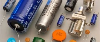
Basic information about the characteristics of capacitors, which are components of almost all electronic circuits, is usually placed on their cases. Depending on the standard size of the element, manufacturer, production time, the data applied to the electronic device constantly changes not only in composition, but also in appearance.
With a decrease in the size of the case, the composition of alphanumeric designations was changed, encoded, and replaced by color markings. The variety of internal standards used by manufacturers of radio-electronic elements requires certain knowledge to correctly interpret the information printed on an electronic device.
Why is labeling needed?
The purpose of marking electronic components is to allow them to be accurately identified. Capacitor markings include:
- data on the capacitance of the capacitor - the main characteristic of the element;
- information about the rated voltage at which the device remains operational;
- data on the temperature coefficient of the capacitance, which characterizes the process of changing the capacitance of the capacitor depending on changes in ambient temperature;
- percentage of permissible deviation of the capacity from the nominal value indicated on the device body;
- release date.
For capacitors, when connecting which polarity must be observed, information must be provided that allows the element to be correctly oriented in the electronic circuit.
The marking system for capacitors produced at enterprises that were part of the USSR had fundamental differences from the marking system used at that time by foreign companies.
Marking of domestic capacitors
All post-Soviet enterprises are characterized by fairly complete labeling of radioelements, allowing for minor differences in designations.
Capacity
The first and most important parameter of a capacitor is capacitance. In this regard, the value of this characteristic is placed in first place and is encoded with an alphanumeric designation. Since the unit of measurement of capacitance is the farad, the letter designation contains either the symbol of the Cyrillic alphabet “F” or the symbol of the Latin alphabet “F”.
Since the farad is a large value, and the elements used in industry have much smaller values, the units of measurement have a variety of diminutive prefixes (mili-, micro-, nano- and pico). Letters of the Greek alphabet are also used to designate them.
- 1 millifarad is equal to 10-3 farads and is denoted 1mF or 1mF.
- 1 microfarad is equal to 10-6 farads and is designated 1 µF or 1F.
- 1 nanofarad is equal to 10-9 farads and is denoted 1nF or 1nF.
- 1 picofarad is equal to 10-12 farads and is denoted 1pF or 1pF.
If the capacity value is expressed as a fraction, then the letter indicating the dimension of the units of measurement is placed in place of the comma. Thus, the designation 4n7 should be read as 4.7 nanofarads or 4700 picofarads, and the inscription like n47 corresponds to a capacity of 0.47 nanofarads or 470 picofarads.
In the case where the capacitor does not have a rating indicated, the integer value indicates that the capacitance is indicated in picofarads, for example, 1000, and the value expressed as a decimal fraction indicates the rating in microfarads, for example, 0.01.
How to connect and set up the Internet on your TV?
The capacitance of the capacitor indicated on the case rarely corresponds to the actual parameter and deviates from the nominal value within a certain range. The exact capacitance value sought when making capacitors depends on the materials used to manufacture them. The spread of parameters can range from thousandths to tens of percent.
The value of the permissible deviation of the capacitance is indicated on the capacitor body after the nominal value by placing a letter of the Latin or Russian alphabet. For example, the Latin letter J (Russian letter I in the old designation) indicates a deviation range of 5% in one direction or another, and the letter M (Russian V) - 20%.
Such a parameter as the temperature coefficient of capacitance is included in the marking quite rarely and is applied mainly to small-sized elements used in electrical circuits of timing circuits. For identification, either an alphanumeric or color notation system is used.
There is also a combination of letter and color markings. Its options are so diverse that to accurately determine the value of this parameter for each specific type of capacitor, you need to refer to GOSTs or reference books on the corresponding radio components.
Rated voltage
The voltage at which the capacitor will operate for a specified service life while maintaining its characteristics is called the rated voltage. For capacitors of sufficient size, this parameter is applied directly to the body of the element, where the numbers indicate the rated voltage value, and the letters indicate in which units of measurement it is expressed.
For example, the designation 160V or 160V indicates that the nominal voltage is 160 volts. Higher voltages are indicated in kilovolts - kV. On small-sized capacitors, the rated voltage is encoded with one of the letters of the Latin alphabet. For example, the letter I represents a nominal voltage of 1 volt, and the letter Q represents 160 volts.
Date of issue
According to “GOST 30668-2000 Electronic products. Marking”, letters and numbers indicating the year and month of production are indicated.
“4.2.4 When indicating the year and month, first indicate the year of manufacture (the last two digits of the year), then the month - in two digits. If the month is indicated by one digit, then a zero is placed in front of it. For example: 9509 (1995, September).
4.2.5 For products whose overall dimensions do not allow the year and month of manufacture to be indicated in accordance with 4.2.4, the codes given in tables 1 and 2 should be used. The marking codes given in table 1 are repeated every 20 years.”
The date when a particular production was carried out can be displayed not only in the form of numbers, but also in the form of letters. Each year has a relationship with a letter from the Latin alphabet. The months from January to September are designated by numbers from one to nine. The month of October has a relationship with the number zero. November corresponds to the Latin letter N, and December – D.
Location of markings on the body
Labeling plays an important role on any product. It is often placed on the first line on the case and has a capacity value. The same line involves placing the so-called tolerance value on it. If both applications do not fit on this line, then this can be done on the next one.
A similar system is used to apply film-type condensates. The arrangement of elements must be located according to certain regulations, which are produced by GOST or TU for an element of an individual type.
Color marking of domestic radioelements
In the production of lines with so-called automatic types of installation, color application appeared, as well as its direct significance in the entire system.
Today, the most commonly used application is using four colors. In this case, we resorted to using four stripes. So, the first strip together with the second represents the capacitance value in so-called picofarads. The third band indicates the deviation that can be allowed. And the fourth band, in turn, means the voltage of the nominal type.
KM 5V (green)
The next group is receiving ceramic KM capacitors of green color, separated by two fractions; 5V/39k/X3. 5V/4n7J/W9. 5V/3n9k/X3. 5V/4n7J/WO.. 5V/4n7J/WN pure square or rectangular dimensions, solder pins in one direction and solder on different sides. This group of KM green ceramic capacitors is the most expensive of all green ones, 5V group . In the marking, at first it says 5V and you don’t have to decipher it further, it’s not important and doesn’t matter, they are accepted according to the upper value of 5V and that’s it. Price in 2022 S3.015 per 1 gram of KM capacitors 5V
Highly stable capacitors KM 5V are used in medical equipment, measuring instruments and military equipment. The process of manufacturing elements of this type consists of pressing thin metallized ceramic plates under high pressure, which makes it possible to achieve a large electrical capacitance of capacitors with fairly small dimensions.
FK22C0G2A104J
- more
- Industry news
- Contacts
- Integrated circuits
- Capacitors
- Batteries and accumulators
- Sensors
- Audio (speakers, microphones)
- Discrete semiconductors
- Fuses, filters
- Connectors, connectors
- Crystals and Oscillators
- Fans, radiators
- Filters
- Inductors, coils, chokes
- Memory cards and modules
- Motors, solenoids
- Lenses, magnifiers, microscopes
- Optoelectronics
- Potentiometers, variable resistors
- Power supplies
- Relay
- Resistors
- Radio frequency components (RF and RFID)
- Buttons, switches
- Transformers
- Cables, extensions, adapters
- Mounting accessories
- Cables and wires in reels
- OEM products
- Industrial measurement
- UPS, surge protectors
- Housings, boxes, racks
- Fasteners, stickers, screws
- Kits
- Programmers, development systems
- Board blanks and materials
- Soldering Products
- Antistatic equipment
- Electrical tapes, adhesives
- Tools
- Measuring equipment
| — Dimensional drawing - Dimensional drawing | Manufacturer | TDK Corporation |
| Harmful substances | RoHS Lead Free | |
| Series | FK | |
| Capacity | 0.1µF | |
| Rated voltage | 100V | |
| Permissible capacity deviations | ±5% | |
| Temperature coefficient | C0G,NP0 | |
| Installation type | Through Hole | |
| Working temperature | -55°C ~ 125°C | |
| Functional | General Purpose | |
| Step | 5.00 mm (0.197″) | |
| Frame | Radial | |
| Found under the name | 445-2613, FK22COG2A104J | |
| Documentation | e4942_fk.pdf on the website co.jp |
| Photo | Name | Manufacturer | Those. options | Prices (RUB) | Buy |
| FK24C0G2A152J | TDK Corporation | CAP CER 1500PF 100V C0G 5% RAD Series: FK Capacitance: 1500pF Nominal voltage: 100V Capacitance tolerance: ±5% Temperature coefficient: C0G, NP0 Mounting type: Through Hole Operating temperature: -55°C ~ 125 °C Functionality: General Purpose Pitch: 5.00 mm (0.197″) Case: Radial | from 8.30 from 32.84 | Add. informationSearch in suppliersBuy in store | |
| FK24C0G2A472J | TDK Corporation | CAP CER 4700PF 100V C0G 5% RAD Series: FK Capacitance: 4700pF Nominal voltage: 100V Capacitance tolerance: ±5% Temperature coefficient: C0G, NP0 Mounting type: Through Hole Operating temperature: -55°C ~ 125 °C Functionality: General Purpose Pitch: 5.00 mm (0.197″) Case: Radial | from 9.59from 38.03 | Add. informationSearch in suppliersBuy in store | |
| FK24C0G2A392J | TDK Corporation | CAP CER 3900PF 100V C0G 5% RAD Series: FK Capacitance: 3900pF Nominal voltage: 100V Capacitance tolerance: ±5% Temperature coefficient: C0G, NP0 Mounting type: Through Hole Operating temperature: -55°C ~ 125 °C Functionality: General Purpose Pitch: 5.00 mm (0.197″) Case: Radial | from 9.59from 38.03 | Add. informationSearch in suppliersBuy in store | |
| FK28C0G2A561J | TDK Corporation | CAP CER 560PF 100V C0G 5% RAD Series: FK Capacitance: 560pF Nominal voltage: 100V Capacitance tolerance: ±5% Temperature coefficient: C0G, NP0 Mounting type: Through Hole Operating temperature: -55°C ~ 125 °C Functionality: General Purpose Pitch: 5.00 mm (0.197″) Case: Radial | from 6.48 from 25.71 | Add. informationSearch in suppliersBuy in store | |
| FK24C0G2A102J | TDK Corporation | CAP CER 1000PF 100V C0G 5% RAD Series: FK Capacitance: 1000pF Rated voltage: 100V Capacitance tolerance: ±5% Temperature coefficient: C0G, NP0 Mounting type: Through Hole Operating temperature: -55°C ~ 125 °C Functionality: General Purpose Pitch: 5.00 mm (0.197″) Case: Radial | from 14.58 | Add. informationSearch in suppliersBuy in store | |
| FK24C0G2A332J | TDK Corporation | CAP CER 3300PF 100V C0G 5% RAD Series: FK Capacitance: 3300pF Nominal voltage: 100V Capacitance tolerance: ±5% Temperature coefficient: C0G, NP0 Mounting type: Through Hole Operating temperature: -55°C ~ 125 °C Functionality: General Purpose Pitch: 5.00 mm (0.197″) Case: Radial | from 9.59from 38.03 | Add. informationSearch in suppliersBuy in store | |
| FK24C0G2A182J | TDK Corporation | CAP CER 1800PF 100V C0G 5% RAD Series: FK Capacitance: 1800pF Nominal voltage: 100V Capacitance tolerance: ±5% Temperature coefficient: C0G, NP0 Mounting type: Through Hole Operating temperature: -55°C ~ 125 °C Functionality: General Purpose Pitch: 5.00 mm (0.197″) Housing: Radial | from 8.30 from 32.84 | Add. informationSearch in suppliersBuy in store | |
| FK20C0G1H104J | TDK Corporation | CAP CER .10UF 50V C0G RAD Series: FK Capacitance: 0.1µF Nominal voltage: 50V Capacitance tolerance: ±5% Temperature coefficient: C0G, NP0 Mounting type: Through Hole Operating temperature: -55°C ~ 125 °C Functionality: General Purpose Pitch: 5.00 mm (0.197″) Housing: Radial | from 58.34from 230.97 | Add. informationSearch in suppliersBuy in store | |
| FK28C0G2A681J | TDK Corporation | CAP CER 680PF 100V C0G 5% RAD Series: FK Capacitance: 680pF Nominal voltage: 100V Capacitance tolerance: ±5% Temperature coefficient: C0G, NP0 Mounting type: Through Hole Operating temperature: -55°C ~ 125 °C Functionality: General Purpose Pitch: 5.00 mm (0.197″) Case: Radial | from 6.48 from 25.71 | Add. informationSearch in suppliersBuy in store | |
| FK28C0G2A221J | TDK Corporation | CAP CER 220PF 100V C0G 5% RAD Series: FK Capacitance: 220pF Nominal voltage: 100V Capacitance tolerance: ±5% Temperature coefficient: C0G, NP0 Mounting type: Through Hole Operating temperature: -55°C ~ 125 °C Functionality: General Purpose Pitch: 5.00 mm (0.197″) Case: Radial | from 5.96from 23.55 | Add. informationSearch in suppliersBuy in store | |
| FK28C0G2A122J | TDK Corporation | CAP CER 1200PF 100V C0G 5% RAD Series: FK Capacitance: 1200pF Nominal voltage: 100V Capacitance tolerance: ±5% Temperature coefficient: C0G, NP0 Mounting type: Through Hole Operating temperature: -55°C ~ 125 °C Functionality: General Purpose Pitch: 5.00 mm (0.197″) Case: Radial | from 7.00from 27.66 | Add. informationSearch in suppliersBuy in store | |
| FK26C0G2A472J | TDK Corporation | CAP CER 4700PF 100V C0G 5% RAD Series: FK Capacitance: 4700pF Nominal voltage: 100V Capacitance tolerance: ±5% Temperature coefficient: C0G, NP0 Mounting type: Through Hole Operating temperature: -55°C ~ 125 °C Functionality: General Purpose Pitch: 5.00 mm (0.197″) Case: Radial | from 10.89 from 43.21 | Add. informationSearch in suppliersBuy in store | |
| FK26C0G2A103J | TDK Corporation | CAP CER 10000PF 100V C0G 5% RAD Series: FK Capacitance: 10000pF Nominal voltage: 100V Capacitance tolerance: ±5% Temperature coefficient: C0G, NP0 Mounting type: Through Hole Operating temperature: -55°C ~ 125 °C Functionality: General Purpose Pitch: 5.00 mm (0.197″) Case: Radial | from 13.74 from 54.45 | Add. informationSearch in suppliersBuy in store | |
| FK28C0G2A151J | TDK Corporation | CAP CER 150PF 100V C0G 5% RAD Series: FK Capacitance: 150pF Nominal voltage: 100V Capacitance tolerance: ±5% Temperature coefficient: C0G, NP0 Mounting type: Through Hole Operating temperature: -55°C ~ 125 °C Functionality: General Purpose Pitch: 5.00 mm (0.197″) Case: Radial | from 5.96from 23.55 | Add. informationSearch in suppliersBuy in store | |
| FK28C0G2A391J | TDK Corporation | CAP CER 390PF 100V C0G 5% RAD Series: FK Capacitance: 390pF Nominal voltage: 100V Capacitance tolerance: ±5% Temperature coefficient: C0G, NP0 Mounting type: Through Hole Operating temperature: -55°C ~ 125 °C Functionality: General Purpose Pitch: 5.00 mm (0.197″) Case: Radial | from 6.22from 24.63 | Add. informationSearch in suppliersBuy in store | |
| FK28C0G2A121J | TDK Corporation | CAP CER 120PF 100V C0G 5% RAD Series: FK Capacitance: 120pF Nominal voltage: 100V Capacitance tolerance: ±5% Temperature coefficient: C0G, NP0 Mounting type: Through Hole Operating temperature: -55°C ~ 125 °C Functionality: General Purpose Pitch: 5.00 mm (0.197″) Case: Radial | from 5.96from 23.55 | Add. informationSearch in suppliersBuy in store | |
| FK26C0G2A682J | TDK Corporation | CAP CER 6800PF 100V C0G 5% RAD Series: FK Capacitance: 6800pF Nominal voltage: 100V Capacitance tolerance: ±5% Temperature coefficient: C0G, NP0 Mounting type: Through Hole Operating temperature: -55°C ~ 125 °C Functionality: General Purpose Pitch: 5.00 mm (0.197″) Case: Radial | from 10.89 from 43.21 | Add. informationSearch in suppliersBuy in store | |
| FK22C0G2A473J | TDK Corporation | CAP CER 47000PF 100V C0G 5% RAD Series: FK Capacitance: 0.047µF Nominal voltage: 100V Capacitance tolerance: ±5% Temperature coefficient: C0G, NP0 Mounting type: Through Hole Operating temperature: -55°C ~ 125°C Functionality: General Purpose Pitch: 5.00 mm (0.197″) Body: Radial | from 102.63 | Add. informationSearch in suppliersBuy in store | |
| FK22C0G2A683J | TDK Corporation | CAP CER 68000PF 100V C0G 5% RAD Series: FK Capacitance: 0.068µF Nominal voltage: 100V Capacitance tolerance: ±5% Temperature coefficient: C0G, NP0 Mounting type: Through Hole Operating temperature: -55°C ~ 125°C Functionality: General Purpose Pitch: 5.00 mm (0.197″) Body: Radial | from 62.23from 246.31 | Add. informationSearch in suppliersBuy in store | |
| FK20C0G2A333J | TDK Corporation | CAP CER 33000PF 100V C0G 5% RAD Series: FK Capacitance: 0.033µF Nominal voltage: 100V Capacitance tolerance: ±5% Temperature coefficient: C0G, NP0 Mounting type: Through Hole Operating temperature: -55°C ~ 125°C Functionality: General Purpose Pitch: 5.00 mm (0.197″) Body: Radial | from 31.11 from 123.16 | Add. informationSearch in suppliersBuy in store | |
| FK26C0G2A392J | TDK Corporation | CAP CER 3900PF 100V C0G 5% RAD Series: FK Capacitance: 3900pF Nominal voltage: 100V Capacitance tolerance: ±5% Temperature coefficient: C0G, NP0 Mounting type: Through Hole Operating temperature: -55°C ~ 125 °C Functionality: General Purpose Pitch: 5.00 mm (0.197″) Case: Radial | from 10.89 from 43.21 | Add. informationSearch in suppliersBuy in store | |
| FK28C0G2A331J | TDK Corporation | CAP CER 330PF 100V C0G 5% RAD Series: FK Capacitance: 330pF Nominal voltage: 100V Capacitance tolerance: ±5% Temperature coefficient: C0G, NP0 Mounting type: Through Hole Operating temperature: -55°C ~ 125 °C Functionality: General Purpose Pitch: 5.00 mm (0.197″) Case: Radial | from 6.22from 24.63 | Add. informationSearch in suppliersBuy in store | |
| FK24C0G2A122J | TDK Corporation | CAP CER 1200PF 100V C0G 5% RAD Series: FK Capacitance: 1200pF Nominal voltage: 100V Capacitance tolerance: ±5% Temperature coefficient: C0G, NP0 Mounting type: Through Hole Operating temperature: -55°C ~ 125 °C Functionality: General Purpose Pitch: 5.00 mm (0.197″) Case: Radial | from 8.30 from 32.84 | Add. informationSearch in suppliersBuy in store | |
| FK24C0G2A272J | TDK Corporation | CAP CER 2700PF 100V C0G 5% RAD Series: FK Capacitance: 2700pF Nominal voltage: 100V Capacitance tolerance: ±5% Temperature coefficient: C0G, NP0 Mounting type: Through Hole Operating temperature: -55°C ~ 125 °C Functionality: General Purpose Pitch: 5.00 mm (0.197″) Case: Radial | from 9.59from 38.03 | Add. informationSearch in suppliersBuy in store | |
| FK28C0G2A181J | TDK Corporation | CAP CER 180PF 100V C0G 5% RAD Series: FK Capacitance: 180pF Nominal voltage: 100V Capacitance tolerance: ±5% Temperature coefficient: C0G, NP0 Mounting type: Through Hole Operating temperature: -55°C ~ 125 °C Functionality: General Purpose Pitch: 5.00 mm (0.197″) Case: Radial | from 5.96from 23.55 | Add. informationSearch in suppliersBuy in store |
KM N30 (green)
So the next group of green ceramic KM capacitors is the H30 group sold in 2022 for S1.316 per gram. All these capacitors are marked H30, which is why they belong to this group.
Ceramic capacitors KM N30 (green) were developed and put into mass production in the 1970s with the aim of using them in electronic equipment to smooth out DC voltage ripples, as well as to work as part of low-frequency and high-frequency filters. The appearance of the capacitors consists of thin square or rectangular plates, and the contacts can be located in one or the opposite direction.
Capacitor 0.1uF 100V (2A104J, CL11) | Film capacitors
Capacitors of the CL11 series (polyester capacitor) are made of metallized film dielectric. Widely used in industrial and household equipment.
Marking:
- 2A = 100V
- 104 = 100000pF (0.1uF)
- J = ±5%
Dimensions:
Datasheet: Capacitors CL11 Series.pdf
Product code: Update: Voltage: Capacity:
| M-116-11758 |
| 2019-09-20 |
| 100V |
| 4.7nF |
A huge amount of electronic components and technical information on the Dalincom website can make it difficult for you to find and select the required additional radio products, radio components, tools, etc. We have prepared the following information table for you, based on the choices of our other customers.
Related products
| Code | Name | Short description | Rozn. price |
| ** more detailed information (photo, description, labeling, parameters, technical specifications, etc.) can be found by clicking on the product description link | |||
| 11758 | Capacitor 0.1uF 100V (2A104J, CL11) | Film capacitor 0.1uF 100V (marking 2A104J) series CL11 (polyester capacitor) made of metallized film dielectric | 1.5 rub. |
| 3213 | Panel SCS-16 (DIP-16, pitch 2.54mm) | Socket for chips SCS-16 DIP panel 16-pin pitch 2.54mm | 2.5 rub. |
| 10218 | Capacitor 2200uF 50V (JCCON) | Electrolytic capacitors 2200 uF 50V (JCCON, 105°C, size 16×31 mm) | 24 rub. |
| 9728 | Variable resistor WH148-1 (B10K, 15mm) | Variable resistor WH148-1A-3, 10 kOhm, linear characteristic, L=15 mm | 12 rub. |
| 9804 | Capacitor 100uF 50V (JCCON) | Electrolytic capacitors 100 uF 50V (JCCON, LOW ESR, 105°C, size 8x12mm) | 2.4 rub. |
| 928 | Panel SCS-8 (DIP-8, pitch 2.54mm) | Socket for chips SCS-8 DIP panel 8-pin pitch 2.54mm | 1.2 rub. |
| 3551 | Capacitor 0.1uF 630V (CBB22) | Metallized film polypropylene capacitor 0.1uF 630V (CBB22 series) | 4 rub. |
| 11192 | Capacitor 4.7nF 100V (CL11) | Film capacitor 4.7nF 100V (marking 2A472J) series CL11 (polyester capacitor) made of metallized film dielectric | 0.6 rub. |
| 9104 | Trimmer resistor 3296W, 5 kOhm (5K) | Multi-turn trimmer resistor (potentiometer), type 3296W, nominal 5 kOhm | 8.5 rub. |
| 362 | Capacitor 47uF 63V (Jwco) | Electrolytic capacitors 47 uF 63V (6.3x12 mm, LOW ESR, 105°C, radial leads) | 2.4 rub. |
KM D (green)
Now the next group of KM green ceramic capacitors is group D , at the very beginning of the marking there are 4D/47n, 5D/47n and so on, in general, the most important thing is that there is a Latin letter D, also rectangular terminals on different sides, unidirectional. On these we already see the gray color of the capacitor with peeled paint; it contains platinum and palladium. In 2022, they were accepted at S$1.66 per gram.
Radio components KM D (green), being small-sized capacitors resistant to external environmental influences, are designed to store electrical energy in circuits where useful signals change their polarity and high stability of operation of each individual electronic element is required. One of the first enterprises to begin producing capacitors of this type in the 1970s was the Monolit Production Association, which marked its products with a sign in the form of a diamond with arrows on the sides.
[Hot Item] 400V 104j Polyester Film Capacitor
Polyester Film Metallised Capacitor MEF CL211. Functions1.) resistance to high humidity2.) solderability3. ) self-healing property4. ) space saving and small size2.
Applications using metal polyester film capacitor MEF CL21 capacitors are suitable for blocking, coupling, decoupling, filtering, timing chain bypass and are ideal for use in telecommunication equipment, data processing equipment, industrial instrument, automatic control system and other general electronic equipment. 3. specifications
| Capacitance exceeds permissible limits | Mkf~4.7μF 0.0047 |
| Capacitance tolerance | J(±5%),K(±10%),M(±20%) |
| Working temperature | -40~105ºC |
| Rated voltage | 100V,250V,400V,630V DC |
| Power dissipation factor(tgδ) | 1% max @,at 1KHz and 25ºC |
| Insulation Resistance (IR) | IR-≥7500MΩ 0.33C≤μF:IR≥2500S for C>0.33μF |
| Dielectric strength | For 1.4Ur 3~5 seconds |
4. Size(:mm)
| Capacity | 50/63/100V | 160/250V | 400V | 630V | ||||||||||||||||
| (Of) | Wmax | Hmax | Tmax | Р±1 | D±0.05 | Wmax | Hmax | Tmax | Р±1 | D±0.05 | Wmax | Hmax | Tmax | Р±1 | D±0.05 | Wmax | Hmax | Tmax | Р±1 | D±0.05 |
| 0,01 | 12,5 | 11.5 | 7 | 10 | 0,6 | 15,5 | 11.5 | 7 | 12,5 | 0,6 | ||||||||||
| 0,015 | 12,5 | 12,5 | 7.5 | 10 | 0,6 | 15,5 | 12,5 | 7.5 | 12,5 | 0,6 | ||||||||||
| 0,022 | 15,5 | 11.5 | 7 | 12,5 | 0,6 | 15,5 | 11.5 | 7 | 12,5 | 0,6 | ||||||||||
| 0.033 | 15,5 | 12,5 | 8 | 12,5 | 0,6 | 15,5 | 12,5 | 8 | 12,5 | 0,6 | ||||||||||
| 0,047 | 12,5 | 12 | 7 | 10 | 0,6 | 15,5 | 12,5 | 8 | 12,5 | 0,6 | 18 | 12,5 | 8 | 15 | 0,6 | |||||
| 0.068 | 12,5 | 12,5 | 7.5 | 10 | 0,6 | 15,5 | 12,5 | 8.5 | 12,5 | 0,6 | 18 | 13 | 9 | 15 | 0,6 | |||||
| 0,1 | 12,5 | 12 | 7.0 | 10 | 0,6 | 15,5 | 12 | 7 | 12,5 | 0,6 | 18 | 13 | 9 | 15 | 0,6 | 26 | 14.5 | 9 | 22 | 0,8 |
| 0,15 | 12,5 | 12,5 | 7.5 | 10 | 0,6 | 15,5 | 13 | 8.5 | 12,5 | 0,6 | 20.5 | 14.5 | 9 | 17,5 | 0,6 | 26 | 16,5 | 10 | 22 | 0,8 |
| 0,22 | 15,5 | 12,5 | 7.5 | 12,5 | 0,6 | 20.5 | 14 | 7.5 | 17 | 0,6 | 20.5 | 16 | 10.5 | 17,5 | 0,6 | 26 | 19 | 12 | 22 | 0,8 |
| 0,33 | 15,5 | 13 | 8.0 | 12,5 | 0,6 | 20.5 | 14.5 | 8.5 | 17 | 0,6 | 26 | 17,5 | 10.5 | 22 | 0,8 | 26 | 20.5 | 13.5 | 22 | 0,8 |
| 0,47 | 15,5 | 14.5 | 9.0 | 12,5 | 0,6 | 20.5 | 16,5 | 10 | 17 | 0,8 | 26 | 19.5 | 12,5 | 22 | 0,8 | 37,5 | 23,5 | 13 | 32 | 0,8 |
| 0,68 | 20.5 | 14.5 | 8.5 | 17,7 | 0,6 | 20.5 | 18 | 11 | 17 | 0,8 | 26 | 21,5 | 14 | 22 | 0,8 | 37,5 | 25.5 | 15,5 | 32 | 1.0 |
| 1.0 | 20.5 | 15,5 | 10 | 17,5 | 0,8 | 29 | 19 | 10.5 | 25 | 0,8 | 37,5 | 24.5 | 13.5 | 32 | 0,8 | 42,5 | 26.5 | 17 | 37 | 1.0 |
| 1.5 | 20.5 | 17,5 | 11.5 | 17,5 | 0,8 | 29 | 20 | 12 | 25 | 0,8 | 37,5 | 28 | 15,5 | 32 | 1.0 | 42,5 | 29.5 | 19.5 | 37 | 1.0 |
| 2.2 | 26 | 19.5 | 12 | 22 | 0,8 | 29 | 24 | 15 | 25 | 0,8 | 42,5 | 28.5 | 18 | 37 | 1.0 | 42,5 | 32,5 | 22,5 | 37 | 1.0 |
| 3.3 | 26 | 22,5 | 14 | 22 | 0,8 | 41,5 | 24 | 14 | 37 | 0,8 | 42,5 | 32 | 20.5 | 37 | 1.0 | |||||
| 4.7 | 37,5 | 23,5 | 13 | 32 | 0,8 | 41,5 | 27 | 16 | 37 | 1.0 | 42,5 | 35,5 | 24.5 | 37 | 1.0 | |||||
| 6.8 | 37,5 | 27,5 | 15,5 | 32 | 1.0 | 41,5 | 30 | 20 | 37 | 1.0 | ||||||||||
| 10.0 | 37,5 | 31 | 18 | 32 | 1.0 | 41,5 | 37 | 23,5 | 37 | 1.0 |
Source: https://ru.Made-in-China.com/co_zhengli-capacitor/product_400V-104j-Polyester-Film-Capacitor_eeuehhhug.html
KM 3E, 3F, 3V (green)
The next group of KM green ceramic capacitors is group 3F. 3E. 3V. 3M This group has one difference: the pins of the soldering legs are on one side, but not unidirectional and very small compared to conventional KM green ceramic capacitors from the groups, about four times... The price for them in 2022 was S1.27 per gram.
Ceramic capacitors 3E, 3F, 3V serve to store electrical energy and are used in the designs of high-precision measuring instruments, as well as in devices created on the basis of digital (microprocessor) components. The presented elements have a flat, rectangular shape, and the terminals can be located in both unidirectional and multidirectional designs.
Features of the use of MLCC capacitors in high voltage applications
MLCCs are an excellent alternative to film capacitors in high voltage and power applications. They not only have high resistance to mechanical stress and electrostatics, but also a wide frequency range, low series resistance and high temperature stability. From the features of MLCC described above, the common features of high-voltage capacitors [7] are obvious (Table 4). Firstly, the standard sizes of high-voltage capacitors cannot be miniature. Otherwise, the probability of corona discharge will be too high. Secondly, the capacity of high-voltage capacitors is not large. Since to obtain high electrical strength it is necessary to increase the thickness of the dielectric layers. Third, Y5V ceramics have too high losses and are not suitable for high voltage applications.
Table 4 - Yageo high voltage MLCC capacitors
| Constant operating voltage, (V) | 0805 | 1206 | 1210 | 1808 | 1812 | |
| NPO | 200 | 10pF…560 pF | 10pF…1.5nF | 1.8nF…3.3nF | — | 3.9nF…5.6nF |
| 500 | — | 10pF…1nF | 47pF…1.8nF | — | 2.2nF…3.3nF | |
| 1000 | — | 120pF…390pF | — | — | 100pF…1.5nF | |
| 2000 | — | 22pF…100nF | — | — | — | |
| 3000 | — | — | — | 3.3pF…120pF | 10pF…220pF | |
| 4000 | — | — | — | 10pF…22pF | 10pF…47pF | |
| Accuracy, % | ± 5 | |||||
| X7R | 200 | 220pF…6.8nF | 680pF…33nF | 22nF…47nF | — | 47nF…100nF |
| 500 | — | 470pF…3.3nF | 3.3nF…6.8nF | — | 10nF…15nF | |
| 1000 | — | 470pF…3.3nF | — | 470pF…3.3nF | 1nF…10nF | |
| 2000 | — | — | — | 470pF…2.2nF | 1nF…4.7nF | |
| Accuracy, % | ± 5 | |||||
| Thermal resistance, Rth (°С/W) | 172 | 153 | 137 | 130 | 118 | |
| Lead Coating | Ni/Sn | |||||
It is worth noting that for high-voltage capacitors all the conclusions made in the previous sections regarding the dependence of the breakdown voltage on various factors are valid.
Resistance of MLCC capacitors to mechanical stress
The occurrence of internal mechanical stresses in class 2 capacitors during voltage and temperature changes was described above. However, an important property of the entire class of MLCC capacitors is resistance to mechanical stress [1]. There are two main types of external mechanical influences: pressure on the component during installation on the board before installation and the impact when the printed circuit board is bent during operation. When installing a component on the board, pressure is required to be applied to the component. However, at the moment there is no document regulating pressing force. As a rule, you can find the maximum pressing force values in the manufacturer's documentation. It is important to pay attention to the conditions of the test. Test mechanical effects and conditions for testing when bending boards, unlike the previous case, are standardized (for example, IEC 68-2-21). During testing, the board bends by several millimeters. The latter type of exposure is especially critical for automotive applications. There is a special type of MLCC capacitors “soft termination”, which have increased resistance to such mechanical stress. They use leads based on elastic materials using polymer-silver conductive materials.
KM general group (green)
The next KM green ceramic capacitors are the general group 5P33, 5N90, 5M, price S2,546 in 2020 per gram, it includes all KM capacitors with different markings, except for those items that were listed above.
Small-sized capacitors KM, belonging to the general group and having a green color, are used for operation in AC and DC circuits, as well as in pulse mode. Mass production of such elements began in the 1970s at military and civilian factories, such as the Vitebsk Radio Components Plant, Monolit Production Association, and Mikond (Tashkent). The capacitor housing has a square or rectangular, flat shape, and the contact terminals are placed on both one and opposite sides.
KM K10-26 (green)
KM capacitors K10-26 is the next group of KM ceramic green capacitors, last year's price was S0.756 per gram. These are rare square and rectangular KM capacitors and one of the cheapest KM radio components in this group. Lower case markings are needed only for radio amateurs; this data is not needed for purchasing. There is K10-26 and the rest doesn’t matter!!! They are very rare and very few have ever been seen by collectors to sell them for precious metals. The legs of these KMs are on one side.
radio-electronic components KM K10-26 (green) are necessary for accumulating electrical energy and its rapid transmission to connected circuits (circuits). Such ceramic capacitors are used in devices with increased requirements (military, medical, measuring equipment). The body of the K10-26 element is made in the form of a rectangular or square plate of small thickness and is painted green with appropriate markings.
Breakdown of MLCC capacitors in DC circuits
In such circuits, two types of breakdown are possible: dielectric breakdown and corona discharge. Experimental data (Figure 9) allow us to draw several important conclusions [6]:
- The breakdown voltage of a capacitor is several times higher than the rated operating voltage. For capacitors with an operating voltage of 50 V, the breakdown voltage reaches 1500 V for NPO and 500 V for X7R. However, it is important to understand that these measurements are carried out at room temperature and with a limited time of voltage application, while the operating voltage is determined for the entire operating temperature range and for a test voltage application time of 1000 hours.
- NPO capacitors, all other things being equal, have higher breakdown resistance than X7R.
- Capacitors with lower capacitance values have higher breakdown voltages.
- Capacitors with larger sizes are less prone to breakdown, including being more resistant to corona discharge.
Figure 9 – Dependence of capacitor survival on applied DC voltage
Difficulties of verification
The process of determining the capacitance of a capacitor directly on the board is complicated by the presence of other circuit components - they distort the readings of the device.
First of all, this applies to elements with low resistance to direct current: fuses, inductors, transformer windings. Determining the capacitance of a capacitor without soldering is possible only in the absence of the mentioned components. Semiconductor devices - diodes and transistors - also have an effect.
When checking a capacitor for breakdown by measuring resistance, the multimeter will display the resistance of the Pn junction instead of infinity (on the display “1”). As a result, the state of the capacitor will remain unknown.
Features of measuring the capacitance of MLCC capacitors
When measuring the capacitance of MLCC capacitors, questions often arise regarding the accuracy of the results obtained [1]. Let's clarify the measurement process. To do this, it is again necessary to turn to the characteristics of dielectrics. The dielectric of class 2 capacitors has ferrimagnetic properties. As the temperature changes, the dielectric constant value changes. Accordingly, during measurement the temperature must be within the limits specified by the manufacturer in the documentation. In addition, humidity and pressure parameters can also be specified. So, for example, for X5R ]Yageo[/anchor] the following requirements for measurement conditions: temperature from 15 to 35°C, humidity from 25 to 75%, pressure from 86 kPa to 106 kPa. However, for high-quality measurements the listed requirements are not enough. The process of domain orientation itself is a rather slow process, which means that not only at the time of measurement it is necessary to maintain the temperature, but also before the measurement the capacitors must be kept at a given temperature. Another important feature of capacitance measurement is the choice of test voltage. In this case, the DC bias effect appears. As a result, different measuring instruments will produce different data. This is especially noticeable in the example of large capacitors. Yageo recommends the following measurement conditions:
- Measuring equipment: Agilent 4278 A/ 4284 A/ 4268 A (for C ≤ 22 µF);
- Measuring equipment: Agilent 4284 A/ 4268 A (for C > 22 µF);
- Parameters: C = 10 µF, AC 1 V @ 1 kHz;
- C > 10 µF, AC 0.5 V @ 120 Hz;
Calculation using formulas
Calculation of the nominal capacity of an element is required in 2 cases:
- Electronic equipment designers calculate the parameter when creating circuits.
- In the absence of capacitors of suitable power and capacity, craftsmen use element calculations to select from available parts.
RC circuits are calculated using the value of impedance - complex resistance (Z). Ra - current losses due to heating of circuit participants. Ri and Re — take into account the influence of inductance and capacitance of the elements. At the resistor terminals in the RC circuit, the voltage Uр is inversely proportional to Z.
Thermal resistance increases the potential across the load, and reactive resistance decreases. Operating a capacitor at frequencies above resonant frequencies, when the reactive component of the complex resistance increases, leads to voltage losses. The resonance frequency is inversely proportional to the ability to accumulate charge. From the formula for determining Fр, they calculate what values of C (capacitor capacitance) are required for the operation of the circuit.
To calculate pulse circuits, the circuit time constant is used, which determines the effect of RC on the pulse structure. If the circuit resistance and capacitor charging time are known, the capacitance is calculated using the time constant formula. The truth of the result is influenced by the human factor.
Craftsmen use parallel and series connections of capacitors. The calculation formulas are the reverse of the formulas for resistors. A series connection makes the capacitance smaller in the connection of elements; a parallel circuit adds up the values.