Currently there are the following types of television broadcasting:
- Terrestrial – the signal arrives from the TV tower to the receiver;
- Satellite – the signal arrives from the satellite to the user’s individual dish-antenna;
- Cable – the TV signal is distributed via cable;
- Internet TV – transmission is carried out via Internet cable.
Terrestrial TV stands at the origins of television, but, despite its long history, does not lose its relevance. A huge part of the viewing audience continues to use this type of television broadcasting. The main disadvantage of over-the-air transmission is the coverage area. That is, the further the receiving antenna is from the repeater, the worse the signal is. This problem can be solved to some extent by using an amplifier for the TV antenna.
Let's consider the types of such devices, characteristics for choosing them, pros and cons, as well as ways to make such devices with your own hands in order to amplify the signal yourself.
What is an antenna amplifier
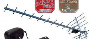
You may have heard the concepts of passive and active antenna. Passive antennas receive signals only due to their shape. But active ones contain some converters to increase the useful signal.
A passive antenna can be made active by adding an amplifier. This option is much more convenient than purchasing an antenna with a built-in amplification device. If it fails, the device is easy to replace. And it can be placed not necessarily on the antenna, but, for example, in the attic, which will allow the device to remain operational longer.
So, a TV amplifier is a device that amplifies the TV signal and reduces the level of interference, which allows you to get a better image on the screen.
The airwaves of television channels are in the range of meter (MV) and decimeter (UHF) frequencies. The former have a frequency from 30 to 300 MHz, and the latter from 300 to 3000 MHz.
According to the range of received frequencies, amplifying devices can be:
- Broadband – covers a wide spectrum of waves;
- Band (work in the decimeter or meter range);
- Multi-band (can operate in both ranges).
As a rule, if the signal is not bad, then it is enough to use a broadband amplifier. In case of poor reception, it is preferable to choose a narrowly targeted device, which in its range will cope with its task much better than a broadband one.
DVB-T2 is a standard used for digital broadcasting. Digital channels are capable of operating only in the UHF range; accordingly, amplifying devices in this range are suitable for digital television.
Amplifying devices also differ in the required supply voltage. The most common are 12-volt. They require an additional power supply. Sometimes the blocks are adjustable.
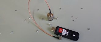
5-volt ones can connect directly to a TV tuner or TV via coaxial cable. Most often they are attached directly to the antenna.
They are also classified according to the type of television, which are called:
- Antenna;
- Satellite;
- Cable.
Cable and satellite amplifying devices are used extremely rarely, since the quality of the signal they transmit is already quite high. In rare cases, an amplifier is used for cable TV if several television devices are connected to the cable.
But antennas are used quite often. Next we will talk specifically about antenna amplifying devices.
Safe distance between parts
Make sure that the planar antenna is not completely covered by a metal casing that could act as a shield. In addition, there should be no metal in the immediate vicinity of the antenna. Also be careful with plastic components - since they usually have a higher dielectric constant than air, they can affect the electrical length of the antenna path, reducing the resonant frequency.
In general, it is best not to place any components directly around it, as they may interfere with operation. The area should also be free of items such as mounting screws or wires. This requirement applies to all layers of the printed circuit board.
You can usually find information in the specification about the size of the recommended protected area around the antenna that should be left unused. But the exact required distance is not always indicated. Instead, antenna manufacturers sometimes define a set of rules that must be followed in real-world conditions.
Advantages and disadvantages of antenna amplifiers
When planning a home television network, you need to take into account the fact that when using several amplifying circuits, the video stream can be significantly distorted. Therefore, the number of such devices should be minimal.
The advantages of these devices include the following:
- It is possible to receive even a weak TV signal;
- Small noise coefficients;
- You can improve the signal in several frequency ranges at once.
Flaws:
- Using a wideband amplification device may overload the permissible signal level, so it should have controls on different bands to avoid this problem;
- Self-excitation of the device;
- Lightning susceptibility;
- Signal loss at the output.
Amplifying devices perform signal correction after the TV antenna. Therefore, which one to choose depends on the area and the needs of the television equipment.
So, installing an amplifier for a TV antenna in a country house or in the countryside very well solves the problem of a weak signal.
Another important point is the power supply. Each amplifier has a power supply, which can be built-in or external. The built-in one will work well if the electrical network is stable and consumes up to 10V. If it burns out, you will have to replace the entire device. Therefore, if the network has voltage surges, it is better to use external units. They are larger in size and have different input voltages depending on the amplifier (5, 12, 18, 24 V).
Equipment Needs
The main task: to minimize cable losses. If the antenna itself does not have enough strength to catch the moving flow, then the microcircuit will not help. The need for a receiver arises if there is a sufficiently large distance between the device and the TV. The abilities will be fully revealed if there is a distance of 30 meters or more. Whatever the cable, the signal weakens as it passes through. You can also purchase a device when reception is from a weak repeater.
Options when there is no need to purchase a product:
- The incoming signal will have a power several times greater than the required value.
- In addition to television channels, the receiver picks up extraneous noise.
- Critical level of reception.
Before proceeding with installation, you must consider the following nuances:
- Availability of power supply. The product is sold simultaneously with the power supply. But there are also exceptions. There is no need if a voltage of 5 V is required. Then you can borrow electricity directly from the tuner. The current flow will be of high quality, there will be no ripple. However, many models require 12 V.
- There is a possibility of burnout when struck by lightning. To reduce the possibility of a negative outcome, lightning protection or grounding is done.
- Time passes and the power supply begins to deteriorate. In this case, the quality of the received signal decreases.
- It becomes possible to enhance the reception of a third-party signal, thereby reducing the quality of the TV channel.
Reasons for signal deterioration
Before deciding to install an antenna amplifying device, you first need to figure out what is the reason for the poor-quality signal:
- The distance to the repeater is too large;
- Incorrect choice or orientation of the TV antenna;
- Presence of obstacles in the signal path: high-rise buildings, buildings, trees, etc.;
- Signal distribution to several receiving devices;
- Cable wear or outdated television equipment.
There is a possibility that you can improve the signal without an amplifier.
To do this you can do the following:
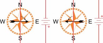
- Try changing the position of the antenna;
- Remove metal objects from the antenna and other objects that are in the signal path;
- Install a more powerful antenna;
- Check the cable for integrity.
If the antenna receives strong interference, or the reception level is greater than the amplifier can withstand, it is better to refuse to use it
It should be understood that the amplifier will increase not only the useful signal, but also interference, since it is not a filter. Therefore, if there is a problem with the signal being too noisy, you should first think about a different antenna. And if the TV signal is too weak, then it will not be amplified.
In addition, if there are twists in the connected cable, this will also increase the amount of noise. It is better to use soldering to connect structural elements.
Digital television is gaining momentum every year. This is due to greater resistance to interference and better quality of the transmitted image. But if the signal is insufficient, the broadcast will be interrupted. This problem is similarly solved by an amplifying device.
A digital TV signal amplifier is no different from any other. It is only important that he works in the DMV. Sometimes it is recommended to install such devices with a voltage of 5V so that they can be connected directly to the tuner. In this case, there is no need for a separate power supply.
Conclusion
Digital television already provides the opportunity to watch TV programs in high definition with minimal hassle and capital costs. But to definitely answer the question “Which home antenna for digital TV is better?” - impossible. You can only expect 100% success if you hire a professional installer who, using his own experience and measurements, will select the right antenna kit for your location. Before making a decision and purchasing a wave receiver, it is also worth looking at the roofs of surrounding buildings and taking advantage of the experience of residents who are already adopting “digital”.
What to look for when choosing an amplifier
Let's look at how to choose antenna amplifiers for a TV. To select a signal amplifier, you need to pay attention to the following parameters:
- Device location. There are mast or external amplification devices, which are installed on the mast, and internal ones - indoors. Using internal antenna amplifiers is much more convenient, but there is also more signal loss. In the UHF it is better to use the mast type;
- Distance to TV tower. The maximum distance should not exceed 150 km, and if less than 10 km there is no need to install an amplifier, it is enough to select and install the antenna correctly;
- Range of frequencies used. If the signal source is weak, then it is better to use a range amplification device for specific frequencies;
- Gain coefficients (GC) and noise of the device. There are special tables for device models where these values are presented. A gain of 15-25 dB is usually sufficient. And the noise figure for UHF should not be more than 3 dB, in other ranges it can reach 6-8 dB;
- Output signal level. This is the maximum signal level above which distortion or interference will occur. The higher this characteristic, the better, but the cost of the device also increases as this parameter increases;
- Number of inputs. If you take an amplifier with several inputs (for each frequency range), then the likelihood of overload increases. It is better to use a separate device for each range.
The gain should not be chosen on the principle of “the more the better.” If the values are too high, the device may overload
What amplification device is suitable for digital TV? For digital broadcasting you need an antenna for UHF with a frequency of 470 MHz or more. Accordingly, the amplifier must also be designed for this range.
Of course, it is impossible to say for sure which device will be the best for your case.
Recently, it has become popular to purchase goods on Chinese websites. Here you can find active antennas with a DVB-T2 amplifier, which are quite acceptable in terms of price-quality ratio.
Chip antennas on printed circuit boards
When designing a circuit board that will include an antenna, finding a suitable location for the component is a key decision. Even if you choose an expensive antenna with high parameters, installing it in the wrong place on the printed circuit board can negatively affect its operation, making it impossible to achieve the performance stated by the manufacturer.
At the outset, it is worth noting that the data included by the manufacturer in the antenna documentation should be approached with caution - this is certainly useful information and is a starting point, but it should be used thoughtfully. For example, it is not recommended to compare different antenna models based solely on this data. The parameters of these devices specified in the data sheets are measured in an optimized environment, while the best antenna for a given application is not the antenna with high free space transmission parameters, but the one that is best suited for the given project.
What to do if the Polish network does not accept DVB T2?
If “Pole” does not receive DVB T2 and does not respond in any way to manual settings, this cannot be the TV’s fault. Many users believe that the basic gain found in modern plasma and LCD devices is sufficient to access digital broadcast levels. According to many sellers, modern TVs have the ability to receive a signal without connecting antennas. However, in practice it turns out that the further a person is from the signal repeater, the worse the reception becomes.
This state of affairs is especially noticeable in remote areas of the country, which recently switched to digital television broadcasting. Repeater towers have to add amplification so that local residents can achieve the same quality as channels in urban areas.
In many cases, the cause of a poor signal when receiving DVB-T2 is increased power. An incorrectly selected translator can significantly increase outgoing performance, which will lead to interference. There are four ways to correct this problem and achieve better digital TV reception.
Source
Is the Polish grid suitable for receiving digital television?
The Polish mesh antenna at one time quickly spread throughout the country and gained popularity among many users. This equipment is easy to maintain and does not require additional modifications after installation. With the advent of DVB-T2 digital broadcasting in the country, users began to find various amplifiers for this type of antenna, allowing them to capture a digital signal and broadcast it to a TV.
The antenna array itself is broadband. In other words, such equipment is capable of receiving various signals of both meter and decimeter range lengths. This unique property allows the device to catch signals from digital TV channels in DVB-T2 format.
The Polish grid is not the most suitable option used for long-distance reception of digital TV channels. This is primarily due to the fact that the device requires modifications and modernization before it begins to function in the required range.
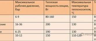
Comparison table of the presented models
To visually compare the models presented above, we use a comparison table.
| Model | Frequency (MHz) | Gain (dB) | Dimensions (mm) | Weight, kg) | Price, rub) |
| Terra HS004 | 47-862 | 34-44 | 135x180x52 | 0.7 | from 3,200 to 3,780 |
| Alcad AL-200 | 47-862 | 14-24 | 101x57x28 | 0.4 | from 1,350 to 1,600 |
| Rexant 05-6202 | 5-2500 | 25 | 60x40x20 | 0.1 | from 190 to 380 |
| Lans LX-50 | 47-862 | 16-20 | 88x76x20 | 0.2 | from 980 to 1,100 |
| One For All SV9345 | 87-862 | 43 | 43x43x213 | 0.7 | from 2,399 to 2,899 |
| REMO BAS-1321 | 87-862 | 43 | 1050x290x90 | 2.3 | from 1,760 to 2,030 |
| Harper ADVB-2440 | 87-862 | 30 | 115x115x235 | 0.5 | from 1,399 to 1,670 |
Grounded Coplanar Waveguide GCPW
In the case of printed circuit boards with chip antennas, it is recommended to make transmission lines in the form of GCPW (Golated Coplanar Waveguide) - a grounded coplanar waveguide. This eliminates the need to connect vias to elements on the underside of the PCB. This is the preferred approach because vias increase transmission line losses and also introduce parasitic inductance in the matching circuits.
RF transmission line as GCPW
GCPW is a conductive path system surrounded by ground planes at a specified distance on both sides. In addition, the signal is isolated on the underside by an additional ground plane. This configuration is well suited for high frequency operation and provides good noise isolation. Another benefit is the flexibility that is offered to designers, giving them many options when it comes to precise impedance matching.
GCPW requires careful design - neglect can have serious consequences, frustrating efforts. As with other types of transmission lines, size, the relationship between individual sizes, and consistency of performance are key. The longer the transmission line, the more distorted the signals traveling along it will be. Therefore, it is important that its length does not exceed 10% of the wavelength, especially in microwave devices, and that the width of the insulating gaps is constant along the entire length of the line.
The gaps should also be thinner than the surrounding mass planes. The width of these slots affects the characteristic impedance, so accuracy in this regard prevents mismatch. In addition, the thickness of the dielectric substrate must be twice the width of the current-carrying track.
Connecting to a TV
You can connect the antenna amplifier as follows:
- You need to install the amplifier as close to the TV as possible. This is true for branded devices and those made by hand. The exception would be room amplifiers that have short cables.
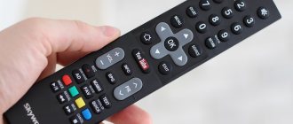
- Be sure to read the instructions before connecting. Often the nuances necessary for quality work are indicated there.
- If, after connecting the device, the picture quality leaves much to be desired, then perhaps the problem is in the integrity of the antenna or in the difference in frequencies.
- Connection should only be made with de-energized devices.
You can connect the device using the coaxial wire of a regular antenna. But for this, a special choke must be located along the power line. If the amplifier is powerful, then for high-quality operation it is connected through a capacitor element with low capacitance. Adjusting the device is easy. It is enough to move the resistor element to the middle and adjust it until the picture is of the highest quality.