Share
Detailed background information on capacitor markings.
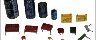
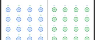
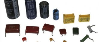
Most capacitors have one or another marking on the case indicating their electrical characteristics. Most often, the following basic parameters are indicated: capacitance, rated voltage and tolerance for capacitance deviation.
On small capacitors, only the capacitance is usually written; If such a device is intended to be used in environments where all three parameters are important, the manufacturer's technical specifications should be consulted. Electrolytic capacitors where polarity is important will have a positive (+) terminal.
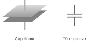
Capacitance units
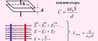
Before proceeding directly to deciphering the codes, it is worth stipulating how the capacity is measured. Despite the fact that its basic unit of measurement is the farad, most capacitors have a capacitance of only a fraction of a farad. An exception is supercapacitors/ionistors, in which the capacitance can reach several farads.
| Unit | Designation |
| Microfarad = 10-6 F | 1 µF, 1 µF, 1 uF, 1 mF |
| Nanofarad = 10-9 F | 1 nF, 1 nF |
| Picofarad = 10-12 F | 1 pF, 1 pF, mmF, uuF |
Sometimes capital letters are used instead of lowercase letters, that is, for example, MF instead of mF (1 MF - 1 microfarad), or instead of F - fd/FD (1 mmfd - 1 picofarad).
There are three types of markings - numbers, a combination of numbers and letters, and color.
Marking capacitors using a numerical-alphabetic code.
The marking of capacitors may indicate the following parameters: Type of capacitor, its rated capacity, permissible deviation of capacitance, Temperature Coefficient of Capacitance (TKE), rated operating voltage.
The order of marking may be different - the first line may be the rated voltage, TKE or the manufacturer's brand name.
TKE may be absent altogether, the rated voltage is also not always indicated! There is almost always a marking of the nominal capacity. As for capacity, there are various ways to encode it symbolically. 1. Marking of the container using three numbers. With this marking, the first two digits indicate the capacitance value in picofarads, and the last one indicates the bit depth, i.e., the number of zeros that must be added to the first two digits. But if the last digit is “9”, division by 10 occurs. Code
| Capacitance(pF) | Capacitance(nF) | Capacitance(uF) | |
| 109 | 1.0(pF) | 0.001(nF) | 0.000001(uF) |
| 159 | 1.5(pF) | 0.0015(nF) | 0.0000015(uF) |
| 229 | 2.2(pF) | 0.0022(nF) | 0.0000022(uF) |
| 339 | 3.3(pF) | 0.0033(nF) | 0.0000033(uF) |
| 479 | 4.7(pF) | 0.0047(nF) | 0.0000047(uF) |
| 689 | 6.8(pF) | 0.0068(nF) | 0.0000068(uF) |
| 100 | 10(pF) | 0.01(nF) | 0.00001(uF) |
| 150 | 15(pF) | 0.015(nF) | 0.000015(uF) |
| 220 | 22(pF) | 0.022(nF) | 0.000022(uF) |
| 330 | 33(pF) | 0.033(nF) | 0.000033(uF) |
| 470 | 47(pF) | 0.047(nF) | 0.000047(uF) |
| 680 | 68(pF) | 0.068(nF) | 0.000068(uF) |
| 101 | 100(pF) | 0.1(nF) | 0.0001(uF) |
| 151 | 150(pF) | 0.15(nF) | 0.00015(uF) |
| 221 | 220(pF) | 0.22(nF) | 0.00022(uF) |
| 331 | 330(pF) | 0.33(nF) | 0.00033(uF) |
| 471 | 470(pF) | 0.47(nF) | 0.00047(uF) |
| 681 | 680(pF) | 0.68(nF) | 0.00068(uF) |
| 102 | 1000(pF) | 1(nF) | 0.001(uF) |
| 152 | 1500(pF) | 1.5(nF) | 0.0015(uF) |
| 222 | 2200(pF) | 2.2(nF) | 0.0022(uF) |
| 332 | 3300(pF) | 3.3(nF) | 0.0033(uF) |
| 472 | 4700(pF) | 4.7(nF) | 0.0047(uF) |
| 682 | 6800(pF) | 6.8(nF) | 0.0068(uF) |
| 103 | 10000(pF) | 10(nF) | 0.01(uF) |
| 153 | 15000(pF) | 15(nF) | 0.015(uF) |
| 223 | 22000(pF) | 22(nF) | 0.022(uF) |
| 333 | 33000(pF) | 33(nF) | 0.033(uF) |
| 473 | 47000(pF) | 47(nF) | 0.047(uF) |
| 683 | 68000(pF) | 68(nF) | 0.068(uF) |
| 104 | 100000(pF) | 100(nF) | 0.1(uF) |
| 154 | 150000(pF) | 150(nF) | 0.15(uF) |
| 224 | 220000(pF) | 220(nF) | 0.22(uF) |
| 334 | 330000(pF) | 330(nF) | 0.33(uF) |
| 474 | 470000(pF) | 470(nF) | 0.47(uF) |
| 684 | 680000(pF) | 680(nF) | 0.68(uF) |
| 105 | 1000000(pF) | 1000(nF) | 1.0(uF) |
2. The second option - marking is done not in pico, but in microfarads, and the letter µ is placed instead of the decimal point.
| Code | Capacitance(uF) |
| µ1 | 0,1 |
| µ47 | 0,47 |
| 1 | 1,0 |
| 4µ7 | 4,7 |
| 10µ | 10,0 |
| 100µ | 100,0 |
3. Third option.
| Code | Capacitance(uF) |
| p10 | 0.1pF |
| IP5 | 0.47pF |
| 332p | 332pF |
| 1HO or 1no | 1nF |
| 15H or 15no | 15.0nF |
| 33H2 or 33n2 | 33.2nF |
| 590H or 590n | 590nF |
| m15 | 0.15uF |
| 1m5 | 1.5uF |
| 33m2 | 33.2uF |
| 330m | 330uF |
| 10m | 10.0uF |
Soviet capacitors used “p” instead of the Latin “r”.
The permissible deviation of the nominal capacity is marked with a letter, often the letter follows the code defining the capacity (the same line).
| Letter designation | Tolerance(%) |
| B | ± 0,1 |
| C | ± 0,25 |
| D | ± 0,5 |
| F | ± 1 |
| G | ± 2 |
| J | ± 5 |
| K | ± 10 |
| M | ± 20 |
| N | ± 30 |
| Q | -10…+30 |
| T | -10…+50 |
| Y | -10…+100 |
| S | -20…+50 |
| Z | -20…+80 |
Further, there may be (or may not be!) marking of the Temperature Coefficient of Capacity (TKE). For capacitors with non-standardized TKE, coding is done using letters.
| Tolerance at -60²…+85²(%) designation | Letter code |
| ± 10 | B |
| ± 20 | Z |
| ± 30 | D |
| ± 50 | X |
| ± 70 | E |
| ± 90 | F |
Capacitors with a linear dependence on temperature.
| TKE(ppm/²C) | Letter code |
| 100(+130….-49) | A |
| 33 | N |
| 0(+30….-47) | C |
| -33(+30….-80) | H |
| -75(+30….-80) | L |
| -150(+30….-105) | P |
| -220(+30….-120) | R |
| -330(+60….-180) | S |
| -470(+60….-210) | T |
| -750(+120….-330) | U |
| -500(-250….-670) | V |
| -2200 | K |
Next comes the voltage in volts, most often in the form of a regular number. For example, the capacitor in this picture is marked with two lines. The first (104J) means that its capacitance is 0.1 μF (104), the permissible deviation of the capacitance does not exceed ± 5% (J). The second (100V) is the voltage in volts.
In addition, the voltage of the capacitors can also be encoded using letters (see table below).
| Voltage (V) | Letter code |
| 1 | I |
| 1,6 | R |
| 3,2 | A |
| 4 | C |
| 6,3 | B |
| 10 | D |
| 16 | E |
| 20 | F |
| 25 | G |
| 32 | H |
| 40 | C |
| 50 | J |
| 63 | K |
| 80 | L |
| 100 | N |
| 125 | P |
| 160 | Q |
| 200 | Z |
| 250 | W |
| 315 | X |
| 400 | Y |
| 450 | U |
| 500 | V |
Tolerances
In accordance with the requirements of IEC Publications 62 and 115-2, the following tolerances and their coding are established for capacitors:
Table 1
| Tolerance [%] | Letter designation | Color |
| ±0,1* | V(W) | |
| ±0,25* | C(U) | orange |
| ±0,5* | D(D) | yellow |
| ±1,0* | F(P) | brown |
| ±2,0 | G(L) | red |
| ±5,0 | J(I) | green |
| ±10 | K(S) | white |
| ±20 | M(V) | black |
| ±30 | N(Ф) | |
| -10…+30 | Q(0) | |
| -10…+50 | T(E] | |
| -10…+100 | Y(Yu) | |
| -20…+50 | S(B) | violet |
| -20,..+80 | Z(A) | grey |
*-For capacitors with a capacity < 10 pF, the tolerance is indicated in picofarads.
Conversion of tolerance from % (δ) to farads (Δ):
Δ=(δхС/100%)[Ф]
Example:
The actual value of the capacitor marked 221J (0.22 nF ±5%) lies in the range: C = 0.22 nF ± Δ = (0.22 ±0.01) nF, where Δ = (0.22 x 10⁻⁹ [F] x 5) x 0.01 = 0.01 nF, or, respectively, from 0.21 to 0.23 nF.
Marking SMD capacitors.
The dimensions of SMD capacitors are small, so their marking is done very succinctly. The operating voltage is often coded by letter (2nd and 3rd options in the figure below) in accordance with the data provided in the previous section. The nominal capacity can be encoded either using a three-digit digital code (option 2 in the figure) or using a two-digit alphanumeric code (option 1 in the figure). When using the latter, you can still find two (and not one letter) with one number on the case (option 3 in the figure).
The first letter can be either a manufacturer's code (which is not always interesting) or indicate the rated operating voltage (more useful information), the second can be an encoded value in picoFarads (mantissa). The number is an exponent (indicates how many zeros need to be added to the mantissa). For example, EA3 may mean that the rated voltage of the capacitor is 16V(E) and the capacitance is 1.0 * 1000 = 1 nanofarad, BF5, respectively, the voltage is 6.3V(V), the capacitance is 1.6 * 100000 = 0.1 microfarad and. etc.
| Letter | Mantissa. |
| A | 1,0 |
| B | 1,1 |
| C | 1,2 |
| D | 1,3 |
| E | 1,5 |
| F | 1,6 |
| G | 1,8 |
| H | 2,0 |
| J | 2,2 |
| K | 2,4 |
| L | 2,7 |
| M | 3,0 |
| N | 3,3 |
| P | 3,6 |
| Q | 3,9 |
| R | 4,3 |
| S | 4,7 |
| T | 5,1 |
| U | 5,6 |
| V | 6,2 |
| W | 6,8 |
| X | 7,5 |
| Y | 8,2 |
| Z | 9,1 |
| a | 2,5 |
| b | 3,5 |
| d | 4,0 |
| e | 4,5 |
| f | 5,0 |
| m | 6,0 |
| n | 7,0 |
| t | 8,0 |
How to determine the rating and voltage
Many manufacturers do not indicate on their products such basic characteristics for any capacitor as operating voltage and rating (nominal capacity).
The rating of these electronic components is determined in the following ways:
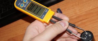
Using a measuring instrument such as a multimeter that has the function of measuring the nominal value. To measure the nominal value, the control probes of the device are connected to special connectors. Then the switch is set to the largest measurement limit (in most multimeters this is 200 µF). After this, the probes are applied to the contacts of the capacitor; after a few seconds, the value of the storage device’s rating is shown on the device’s display.
Important! Before measuring the capacitance, the SMD drive must be discharged - the charge remaining in the plates can damage the electronic circuits of the multimeter. Using a specialized RLC measuring instrument
Using a specialized RLC measuring device.
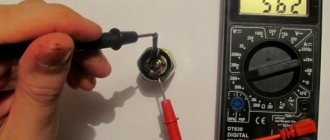
In order to find out the operating voltage of an SMD storage device, use the following simple method:
- Using a multimeter, measure the voltage between the terminals of the component included in the circuit;
- The resulting value is multiplied by 1.5.
The operating voltage calculated in this way will be approximate; a more accurate value of this characteristic can be found from the marking code of the capacitor or its description.
Color coding of ceramic capacitors.
Colored stripes are applied on the capacitor body, from left to right, or from top to bottom.
As a rule, the capacity value is encoded by the first three stripes. Each color in the first two stripes has its own number: black - number 0; brown - 1; red - 2; orange - 3; yellow - 4; green - 5; blue - 6; purple - 7; gray - 8; white - 9. Thus, if, for example, the first stripe is brown and the second is yellow, then this corresponds to the number -14. But this number will not be the value of the nominal capacitance of the capacitor; it still needs to be multiplied by the multiplier encoded by the third stripe.
In the third stripe, the colors have the following meanings: orange - 1000; yellow - 10000; green - 100000. Let's assume that the color of the third strip of our capacitor is yellow. We multiply 14 by 10000, we get the capacity in picofarads -140000, otherwise, 140 nanofarads or 0.14 microfarads. The fourth strip indicates permissible deviations from the nominal capacity (accuracy), as a percentage: white - ± 10%; black - ± 20%. The fifth bar is the rated operating voltage. Red color - 250 Volts, yellow - 400.
Multiples of capacity units
In most cases in electrical engineering, parts with small capacitance values are operated. Sometimes you will see designations such as 10uf capacitor. An inexperienced person may not immediately understand what the abbreviation uf means. It should be understood that the most common units in the description of capacitive elements are the following units: picofarad (or pF, it is equal to 10-12 F), nanofarad (nF, 10-9 F) and microfarad (μF, 10-6 F). Specifying the capacitance of a capacitor in uf means microfarads. It is advisable to purchase a table for converting measurement units of different scales to each other.
Multiple units are not used that often in practice. For some ionistor parts with a binary electrical layer, the capacitance indicator can be measured in kilofarads (kF, 1000 F). The value of standard capacitor elements usually does not exceed hundreds of farads.
Ionistor with a nominal value of 1 farad
Color coding of electrolytic capacitors.
As for small-sized electrolytic capacitors, their nominal capacity is coded using two stripes and one color spot.
The first and second bars determine the number, and the spot determines the multiplier. The color coding of the first two stripes of electrolytic capacitors fully corresponds to the marking of ceramic capacitors. It is only necessary to take into account that the capacitance value of “electrolytes” is obtained in microfarads, and not picofarads as with ceramic capacitors. The color of the spot indicating the multiplier: black - 1; brown - 10; red - 100; gray - 0.01; white - 0.1; For example, the color of the first stripe is blue (number 6), the second is orange (number 3), and the color of the spot is brown (multiplier - 10). This means 63*10= 630 microfarads. If an electrolytic capacitor has a third stripe, then it determines its rated voltage: white color - 3 volts; yellow - 6.3 volts; black - 10 volts; green - 16 volts; blue - 20 volts; gray - 25 volts; pink - 35 volts.
The positive terminal in such electrolytic capacitors is thicker than the negative terminal.
The use of any materials from this page is permitted provided there is a link to the “Electrical is Easy” website.
Storage Features
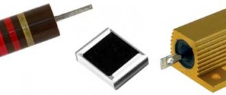
Tantalum capacitors are able to maintain performance characteristics for a long time. If the required conditions are observed (temperature up to +40°, relative humidity 60%), the capacitor loses its ability to be soldered during long-term storage, while maintaining other performance characteristics.
General recommendations for extending the service life of a tantalum capacitor and increasing the safety of its operation:
- Compliance with technical process requirements;
- Multi-stage product quality control;
- Compliance with storage conditions;
- Fulfilling the requirements for organizing a workplace for mounting devices on a board;
- Compliance with the recommended soldering temperature conditions;
- Correct selection of safe operating modes;
- Compliance with operating requirements.