Capacitors have found very wide application in electronics and electrical engineering in our time, because they are the main elements of most electrical circuits and circuits. In this article we will try to explain in detail what the electrical capacity of a capacitor is. The calculation formulas used will also be given, various types of such devices will be described and their markings will be discussed. In addition, the influence of various factors on the capacitance of the capacitor will be affected.
Capacitor
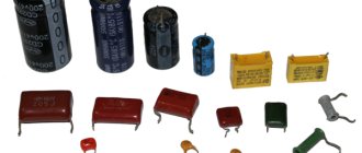
Before you figure out what the capacity of a simple capacitor is, you need to decide what this electrical element is. A capacitor is a radio-electronic part that can accumulate and release a certain portion of electrical charge. The device consists of the following elements:
- Cases. Often made of aluminum. It can be flat, spherical or cylindrical in shape.
- Covers (2 or more). They are made from metal plates or foil.
- Dielectric gasket. It is installed between the plates and serves as an insulator.
- Two or more output contacts for connecting the device to an electrical circuit.
This type of electric charge storage device works as follows.
- When an element is connected to a source of electric current, it acts as a conductor. At this moment, the electric current is at its maximum value and the voltage is at its minimum.
- Positive and negative charges (electrons and ions) begin to accumulate on the plates of the element. This way the device itself is charged. At the time of charging, the strength of the electric current gradually decreases, and the voltage, on the contrary, increases.
- After the amount of charge in the capacitor exceeds the permissible limit, it is discharged and the process begins to repeat cyclically again.
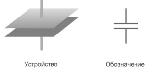
The basis for the performance of this device is its capacity. It is this parameter that determines the charge accumulation time and the total “capacity” of the device. The following figure below will help you understand how the simplest capacitor is indicated on the diagrams.
Electric capacitance, like the capacitors themselves, have found a wide range of applications. They are used as:
- Frequency filters.
- Pulse source for various photographic equipment.
- Smoothers of pulsating currents in rectifiers.
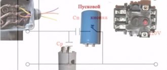
- Phase shifting elements for electric motors.
The use of capacitors in various fields is based precisely on the ability of the device to accumulate electrical charge. In more complex electrical equipment, these devices are used to uninterruptedly maintain a certain voltage in different data storage devices.
Capacity
The capacitance of a capacitor is a physical quantity that determines the relationship between the accumulated charge on the plates and the potential difference between them.
In the SI system, the capacitance of a capacitor and its unit of measurement is Farad. In formulas, the letter Ф (F) is used to denote it. However, capacitor capacitance is rarely measured in Farads because it is quite a large value. Most often, its multiples and submultiples are used.
The value of the electrical capacitance of a capacitor can always be found in the device markings, which are printed on its body.
In the diagram, the element is designated by the letter “C”. The designation of the capacity is a prerequisite, because this will simplify the process of selecting the necessary electrical components for the circuit.
Basic concepts related to electrical capacity
If a conductor receives a charge q, a potential φ arises on it. This potential depends on geometry and environment - for different conductors and conditions, the same charge will cause different potentials. But φ is always proportional to q:
φ=Cq
Coefficient C is called electrical capacitance. If we are talking about a system of several conductors (usually two), then when a charge is imparted to one conductor (plating), a potential difference or voltage U arises:
U=Cq, hence C=U/q
Capacitance can be defined as the ratio of the potential difference to the charge that caused it. The SI unit of measurement of capacitance is the Farad (formerly called Farad). 1 F = 1 V/1 C. In other words, a system has a capacity of 1 farad in which, when a charge of 1 coulomb is imparted, a potential difference of 1 volt arises. 1 Farad is a very large value. In practice, fractional values are most often used - picofarad, nanofarad, microfarad.
In practice, such a connection makes it possible to obtain a battery that can withstand a higher dielectric breakdown voltage than that of a single cell.
Addiction
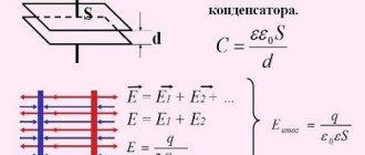
Thanks to the description given earlier, we learned what capacity is. Next, we will try to figure out what this characteristic depends on. The capacitance of the capacitor depends on the distance between the plates, their area, as well as on the dielectric material itself. Thanks to this, we can say what the capacitance of the device depends on: it is directly proportional to the area of the capacitor plate and inversely proportional to the distance between the plates.
Let's consider how to find this value. For a flat capacitor, the formula for calculating capacitance is as follows:
The dependence of the device’s ability to accumulate charge on the area of its plates and the thickness of the dielectric layer also indicates that this value is also influenced by the overall dimensions of the element.
Series and parallel connection of capacitors
Capacitors can be connected in series or in parallel, resulting in a set with new characteristics.
Parallel connection
If you connect capacitors in parallel, then the total capacity of the resulting battery is equal to the sum of all the capacitances of its components. If the battery consists of capacitors of identical design, this can be considered as adding the area of all the plates. In this case, the voltage on each battery cell will be the same, and the charges will add up. For three parallel connected capacitors:
- U=U1=U2=U3;
- q=q1+q2+q3;
- C=C1+C2+C3.
Calculation
Calculation of the capacitance of the capacitor is done using a fairly simple formula:
In this formula:
- q is the amount of charge accumulated by the capacitor.
- φ1−φ2 is the potential difference between its plates.
This expression helps to quite easily calculate the capacitance of any flat-plate capacitor. As mentioned earlier in the article, this value of the electrical capacity of capacitors always depends on its geometric dimensions.
Flat capacitor
A distinctive feature of a flat-plate capacitor is the presence of two parallel plates. Such devices can have a square, round or rectangular shape.
Let us next consider how to determine the capacitance of this type of capacitor. The following formula will always help you find the capacitance of this type of capacitor:
Electrical capacity
Often, the use of capacitors involves connecting several such elements into a circuit at once. Thanks to this, the total capacity can be increased. The formula for determining the electrical capacity of a flat capacitor when connected in parallel is as follows:
Determining the total capacitance for such an electrical circuit is done as follows: C=C1+C2
The amount of charge and voltage for such a connection circuit is determined as follows:
qtot=q1+q2
Utot=U1=U2
The formula will allow you to determine the capacitance of a capacitor for a series connection of elements:
That is, in this case, the total electrical capacity of a flat capacitor is found using the expression:
1/Ctot=1/C1+1/C1
Using these expressions, we will find the total voltage and determine the amount of charge for a series connection of elements:
qtotal=q1=q2
Utot=U1+U2
The capacitance of the capacitor and the calculation formulas used for various connection options for flat devices are shown in the figure below. We can say that it is very visual and easy to use:
Spherical capacitor
The spherical device has two plates in the form of concentric spheres, between which a dielectric is located. The capacitance of a spherical capacitor can be determined as follows:
In this expression, the value “4π” determines the coefficient of charge dissipation on the surface of spherical planes.
The capacitance of a spherical capacitor can be calculated using the formula for a flat device if the gap is quite small compared to the radius of the sphere.
Cylindrical
The cylindrical device is slightly similar to the previously described spherical one. They use similar-shaped linings. They also have a round shape, which means that the calculation of the capacity of a cylindrical device will also be influenced by such a parameter as the radius of the plates. The difference lies only in the most elongated shape of the plates of the cylindrical capacitor. The capacity of a cylindrical capacitor is determined by the formula:
Spherical and cylindrical types of elements are highly dependent on the thickness of the dielectric layer. The thicker it is, the smaller the charge volume will be, which means its resistance to breakdown voltage will increase.
Oscilloscope
With acceptable accuracy, you can determine the capacitance of a capacitor using a digital or conventional electronic oscilloscope. The principle is similar to the method of measuring capacitance with a tester. The only difference is that a stopwatch is not required, since the charging time of the capacitor is displayed with high accuracy on the oscilloscope screen. If you use a frequency generator and a serial RC chain (Fig. 4), then the capacitance can be calculated using a simple formula: C = UR / UC* ( 1 / 2*π*f* R )
.
Rice.
4. Simple scheme The calculation algorithm is simple:
- Connect the oscilloscope to the electrical circuit. When connecting the device probes to electrolytes, observe the polarity of the electric current.
- Measure the voltage amplitudes across the capacitor and resistor.
- By adjusting the generator frequency, ensure that the amplitude values on both elements are equal (at least approximately).
- Substitute the obtained values into the formula and calculate the capacitance of the capacitor.
When measuring the capacitances of non-polar capacitors, instead of an RC circuit, a bridge circuit with a frequency generator (shown in Fig. 5), as well as other assemblies, are often assembled. The resistance of the resistors is selected depending on the parameters of the rated voltages of the parts being measured. Capacity is calculated from the ratio: r4 / Cx = r2 / C0.
Figure 5. Bridge circuit
Examination
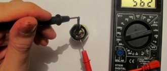
As noted earlier, the capacity of the device is marked on its body. You can check the rated value and the available capacity of the device using a tester with the “CX” mode. For example, the popular models M890D, AM-1083, DT9205A, UT139C, and others are suitable for this. Next you will need:
- Unsolder and discharge the device. Discharge is carried out with a strictly insulated metal object.
- Insert the legs of the capacitor into the grooves “CX”, observing the polarity.
- The device will display the measurement result on the display. It will need to be compared with the one indicated in the markings on its body. If the values differ greatly from each other, this indicates that the element is faulty and requires replacement.
If the multimeter shows the presence of infinite capacity, then this indicates a short circuit inside the device body and it is also considered faulty and requires replacement. In addition, the malfunction can always be determined visually by cracks or swelling of the housing.