Capacitors are devices that store electrical energy in the form of charges. The devices cannot pass direct current through themselves. Being connected to a circuit with alternating current, it is likened to a spring subjected to external influence. It is noteworthy that they will not allow current to pass through, but when it passes, the drive will recharge, which will make it seem like it is passing through the plates. If a constant voltage is applied to them in a discharged state, then a current will flow through the circuit, which decreases as the drive charges. When voltage parity is reached between the power supply and the plates, it stops flowing, causing a rupture.
What is a capacitor
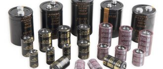
Capacitors are passive elements used in the formation of various electrical circuits, blocking and protective devices. When connected to an alternating circuit, the storage device accumulates and returns energy. If an AC is connected, then the energy is returned to the system, while maintaining a periodicity that corresponds to the operating frequency.
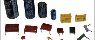
What are capacitors
For your information! When alternating current flows through a capacitor, it continuously provides resistance, the magnitude of which is inversely proportional to frequency.
A decrease in frequency leads to an increase in resistance. When a source generating such current is connected to a storage device, the maximum voltage is determined by the strength.
To use an example to verify the possibility of conducting alternating current, a simple electrical circuit is formed, including the following components:
- variable sources;
- capacitor;
- the consumer is usually a light bulb.
Circuit with a capacitor
Being included in a variable, the capacitor is recharged from time to time, acquiring and releasing charges. Consequently, electricity is exchanged between the source and the two-terminal network, which leads to the formation of reactive energy.
Note! The device does not allow transmission through a permanent network, since in this case the existing resistance will be equal to infinity. If a variable passes through, then the resistance will have a finite value.
TIPS FOR SELECTING AND USING CAPACITORS
The operational reliability of capacitors is largely determined by the correct choice of capacitor types when designing equipment and using them in modes not exceeding permissible ones. To select the correct capacitors, it is necessary to determine, based on an analysis of the equipment requirements:
- values of nominal parameters and their permissible changes during operation (capacitance, voltage, insulation resistance, etc.);
- permissible modes and operating electrical loads (operating frequency range, amplitude and frequency of the alternating voltage component, reactive power, pulse mode parameters);
- operational factors (range of operating temperatures, magnitude of mechanical loads and relative ambient humidity);
- indicators of reliability, durability and storage of capacitors;
- capacitor design, installation methods, dimensions and weight.
In order to increase the reliability and durability of capacitors, in all possible cases they should be used under less severe loads and in lighter modes than permissible.
Installation and fastening of capacitors . The methods used for mounting and fastening capacitors must provide the necessary mechanical strength, reliable electrical contact and the exclusion of resonance phenomena during exposure to vibration loads. Depending on the design, capacitors are fastened to the chassis, panels and equipment boards using fastening devices (flanges, threaded connections), using brackets, clamps, rivets, or by gluing, filling and soldering to the terminals. Fastening devices must not damage the housing and protective coatings of the capacitors. Mounting devices must not impair the conditions for heat removal from the capacitors. It is not allowed to use the spade terminals of capacitors to solder other parts to them.
Mountings for vacuum capacitors, which are also contact devices, must be made of materials with high thermal conductivity and ensure good thermal and electrical contact with the terminals of the capacitors. The surfaces of the fastenings mating with the terminals of the capacitors must be silver plated. When installing in equipment, capacitors should be secured without distortions, since the presence of the latter creates mechanical stress in the cylinder and can lead to loss of tightness and failure of the capacitor. The terminals of the outer electrodes of the capacitors should be connected to a low-potential point of the device or grounded. For variable capacitors, it is recommended to ground the terminal of the moving electrode. When pairing the adjusting screw of a variable capacitor with the output of the drive, attention should be paid to ensuring the alignment of these elements or to provide for their flexible connection.
Contacting the capacitor terminals with other elements is usually done by soldering or welding. Soldering should be done with acid-free fluxes; in this case, dangerous overheating of the capacitor output nodes should not occur. It is allowed to solder the leads at distances from the housing smaller than those specified in the standard documentation, while protecting the contact unit from overheating and damage using thermal shields and heat sinks, as well as one-time bending of the wire and petal leads of the capacitors, provided that the contact unit is protected from damage at the time of bending. The bending radius of the leads must be at least one and a half diameter of the wire lead or one and a half thickness of the tape lead. When installing non-polar capacitors with an oxide dielectric, it is necessary to ensure that their cases are insulated from other elements, the chassis and from each other.
Operating principle of a capacitor
Connecting the device to a constant source leads to the fact that at the initial moment there is an accumulation in the plates due to electrostatic induction, and the resistance at this moment is equal to zero. Electrical induction provokes a field to attract opposite charges onto different plates located opposite each other.
You may be interested in this Editor for drawing diagrams
This property is called capacitance, which is characteristic of all types of materials, including dielectrics, but in the case of conductors it is significantly greater. That is why the plates are made of conductor. An increase in capacity contributes to the accumulation of more charges on the plates.
Important! When charges accumulate, the field weakens and the two-terminal network increases.
Principle of operation
This happens due to a decrease in space in the plates and the influence of charges of the same name on each other. At the same time, the voltage is equal to the current source. The cessation of electricity in the circuit occurs after the plates are completely filled with electricity. Because of this, induction disappears and only a field remains that holds and does not allow charges to pass through.
Dielectric between plates
The electric current will have nowhere to go, and on a two-terminal network the voltage is equal to the EMF. When the EMF increases, the field acts more strongly on the dielectric due to the lack of space in the plates. If the internal capacitor voltage is higher than the limit values, then the dielectric will break through.
The capacitor is converted into a conductor, and charges are released, causing an electric current to flow. To use a two-terminal network at high voltage, increase the size of the dielectric and increase the distance between the plates while reducing the capacitance. The dielectric is located between the plates and does not allow the constant to pass through, performing a barrier function in relation to it.
Electrical induction
Note! It is direct voltage that can form electrostatic induction, but only in the case of a short circuit at the time of charging the capacitor. Thanks to this mechanism, energy is saved until the consumer is connected to it.
Capacitor in DC circuit
To understand how a storage device works in a DC circuit, you need to add a light bulb to the circuit, which will light up only during charging, during which the voltage remains from the electric current, as if catching up with it due to a smooth increase. Charges of electricity take some time to move to the plates; this is precisely the charging time, the duration of which is determined by the frequency and voltage capacitance. When charging is complete, the light goes out and no constant current flows through the passive electronic component.
Capacitor in AC circuit
If the polarity of the source is changed, this will lead to the discharge of the capacitor in the alternating current circuit and its recharging. A constant electrostatic induction is formed with an alternating one. Whenever electricity changes its direction, the charging and discharging mechanism is triggered, which is why it passes the variable. An increase in frequency leads to a decrease in the capacitive reactance of a two-terminal network.
You might be interested in Features of a wind generator for home
Capacitor in a constant circuit
These mysterious capacitors
This article is about the features of ceramic capacitors that appear at high frequencies (of the order of tens, hundreds of megahertz and higher). The article is based on research materials conducted by specialists from Johanson Technology. We will mainly talk about ceramic capacitors suitable for use in:
- High-speed digital devices (filtering of own and external interference);
- High-frequency devices (filtering, RF matching, RF signal processing, etc.);
- Any other devices for filtering external high-frequency interference, which can come both through power circuits and through the air from wireless communication devices and systems, radio stations, power electronics devices, etc.
In the production of such capacitors, special dielectrics are used, which are called NPO
or
COG
.
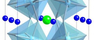
These dielectrics are known for providing a weak dependence of the capacitor's capacitance on the ambient temperature and applied voltage. Most often, to reduce their size, ceramic capacitors are made in the form of multilayer ceramic capacitors - MLCC, Multilayer Ceramic Capacitor
, the structure of which is shown in the following picture:
Johanson Technology is one of the world leaders in the production of high-frequency ceramic capacitors.
, the materials of which served as the basis for this article.
What happens to capacitors as the frequency increases?
As the operating frequency increases, the first “special” frequency that researchers encounter is the series resonant frequency – SRF, Series Resonant Frequency
. As you know from a physics course, this is the frequency at which the reactance of an ideal capacitor is compensated by the reactance of a series-connected ideal inductor in such a way that the total resistance of the circuit becomes zero. In the case of a ceramic capacitor, the phenomenon of series resonance is explained by the presence of parasitic inductance of the leads and plates of the capacitor. And the remarkable SRF in our case is as follows:
- At series resonance frequency (SRF), the capacitor has the lowest resistance, called equivalent series resistance - ESR, Equivalent Series Resistance
. This fact makes it possible to obtain a narrow-band filter instead of a capacitor, which can be used to filter out interference. - At frequencies higher than SRF, the capacitor behaves like an inductor! Therefore, it is sometimes said that at frequencies above the series resonance frequency, the capacitor is an inductance that does not allow direct current to pass through - DC blocking inductor
.
As the frequency increases further, a number of frequencies can be observed at which the multilayer capacitor has a relatively high resistance. Such frequencies are called parallel resonance frequencies - PRF, Parallel Resonant Frequency
. The presence of a series of parallel resonances is explained by the presence of parasitic capacitances connected in parallel with the “DC blocking inductor”.
It is interesting to note that in the general case, according to experimental data, a rough estimate of the frequency of the first parallel resonance can be obtained by doubling the frequency of the series resonance.
Another interesting fact is that you can get rid of all odd frequencies of parallel resonance, including the first one, simply by placing the plates of the internal plates of a multilayer capacitor not parallel to the surface of the printed circuit board, but perpendicular!
Look at the example of the dependence of the introduced attenuation on the frequency for two variants of the arrangement of the plates, which is given by Johanson:
In the top picture the capacitor plates are located parallel to the printed circuit board, and in the bottom picture they are perpendicular.
It is assumed that the disappearance of odd PRF frequencies is due to a decrease in parasitic capacitances between the ceramic capacitor plates and the printed circuit board. But why do the odd resonances disappear and the even ones remain? If you have any thoughts on this matter, welcome in the comments!
Since the SRF and PRF frequencies of ceramic capacitors can range over a very wide range, information about them becomes vital when designing electronic devices. In its documentation, Johanson Technology provides the values of these frequencies, with the PRF frequency corresponding to the frequency of the first parallel resonance (the capacitor plates are parallel to the board surface).
Here are typical resonant frequencies for Johanson Technology size 0402 capacitors:
And typical values of resonant frequencies for Johanson Technology capacitors size 0603:
As we can see, resonant frequencies move to lower frequencies as the capacitance increases and the size of the capacitors decreases. And this leads to a narrowing of the range of operating frequencies in the case where it is necessary for this capacitor to behave like... a capacitor!
Practical recommendations
- Carefully study the documentation for the capacitors you use to avoid situations where the “correct” circuit does not work correctly.
- Do not use low-frequency ceramic capacitors or capacitors with unknown characteristics (and especially electrolytic capacitors) to filter high-frequency interference.
- Determine the frequency ranges of interference and select filter capacitors based on these ranges. Take into account the inductance of the conductors, which is comparable to the parasitic inductance of high-frequency capacitors. To calculate the inductance of a conductor, you can use the formula: where L is the inductance, nH, x is the length of the conductor, cm, w is the width of the conductor, cm, h is the height of the conductor, cm.
- Follow the recommendations of electronic component manufacturers regarding the layout of high-frequency printed circuit boards.
- To expand the operating range, the ceramic capacitor can be installed on its side (eliminating the first parallel resonance).
- In high-frequency circuits, the series resonance frequencies of the capacitors used must be significantly higher than the operating frequency range.
To reinforce this idea, Johanson Technology experts give an example from their own experience, when, when the operating frequency approached the series resonance frequency, a capacitor with a capacity of 10 pF behaved like a capacitor with a capacity of 1000 pF! If the device uses a Bluetooth, Wi-Fi, GSM, GPS, etc. wireless communication module with an external antenna, then it is usually recommended to provide places in the antenna circuit for installing matching elements (placeholders). This allows, if necessary, painless adjustment of the high-frequency part of the boards. To simplify this task, Johanson Technology proposes to use special boxes of high-frequency components, which make the process of matching RF circuits less labor-intensive.
Why does alternating current flow through a capacitor?
A capacitor is a discontinuity because its pads do not touch each other due to the presence of a dielectric between them that does not conduct direct current. However, being connected to a permanent circuit, it can still conduct it at the moment of connection, since charging or recharging occurs.
When the transient process is completed, current stops flowing through the passive electronic component due to the separation of its plates by the dielectric. Being connected to such a circuit, it conducts its oscillations due to cyclic recharging. Here the device enters the oscillatory circuit and, together with the coil, performs the function of an energy storage device.
This symbiosis promotes the conversion of electricity into magnetic energy or, conversely, at an equal frequency rate, which is calculated by the formula: omega = 1 / sqrt(C × L).
Why is there alternating current?
The reality is that a capacitor is not capable of passing alternating current through itself. First, he accumulates it on the covers. A situation arises in which there is an excess of electrons on one of them, and on the other, there are few of them. As a result, the capacitor gives up these charges, due to which the electrons in the external circuit move in one direction and the other from one plate to another.
For your information! The result is that electrons move within the external circuit, but not in the passive component itself. The energy is redistributed within the field between the capacitor plates, which is called displacement currents, which differ from conduction currents.
Conduction triangle for a capacitor
We divide the sides of the current triangles, expressed in units of current, by the voltage U. We obtain a similar conductivity triangle (Fig. 13.16, b), the legs of which are active G = IG/U and capacitive Вс = Iс/U conductivity, and the hypotenuse is the total conductivity of the circuit Y = I/U . From the triangle of conductivities
The relationship between the effective values of voltage and current is expressed by the formulas
I = UY
U = I/Y (13.35)
From the triangles of currents and conductivities, determine the quantities
cosφ = IG/I = G/Y; sinφ = Ic/I = Bc/Y; tanφ = IC/IG = Bc/G. (13.36)
Formulas for calculating current in a capacitor
The capacitance of a capacitor connected to an alternating current circuit is calculated by the formula: C = q / U, where:
- C - capacity;
- q is the charge of one of the plates;
- U is the voltage inside.
Capacitance
Capacitors come in different shapes, so they are calculated using several formulas:
- flat - C = E × E0 × S / d;
- cylindrical - C=2 π × E × E0 × l / ln(R2 / R1);
- spherical - C = 4 π × E × E0 × R1 × R2 / R2 - R.
Note! The resistance in a variable circuit that a resistor connected to an electrical circuit can provide cannot be calculated, since it is considered infinitely large. However, in this case, this can be done using the formula: Xc = 1 / 2πvC = 1 / wC.
You may be interested in this All about uninterruptible power supply
The capacitor voltage in an AC circuit is calculated using the following formula: Wp = qd E / 2.
The voltage is calculated using a certain formula
To calculate the voltage across a capacitor in an AC circuit, you need to use current formulas.
Vector diagram of currents in a circuit with a capacitor
To determine the effective value of the total current I using the vector addition method, we construct a vector diagram according to the equation
I = IG + IC
Effective values of current components:
IG = GU (13.31)
IC = BCU (13.32)
The first on the vector diagram is the voltage vector U (Fig. 13.16, a), its direction coincides with the positive direction of the axis from which the phase angles are measured (initial voltage phase φa = 0). Vector I G coincides in direction with vector U, and vector IC is directed perpendicular to vector U with a positive angle. From the vector diagram it can be seen that the total voltage vector lags behind the total current vector by an angle φ , the value of which is greater than zero, but less than 90º. Vector I is the hypotenuse of a right triangle, the legs of which are its constituent vectors IG and IC:
At voltage u = Umsinωt, according to the vector diagram, the current equation
i = Imsin(ωt + φ)
Where and why are capacitors used?
Where and why are these devices, which can operate in radio engineering, electronic and electrical devices, used? Drives are used in electrical engineering when switching on asynchronous motors for phase shifting, without which the motor as part of a single-phase circuit will not function. If the capacity is several farads, then they are used in electric vehicles to power the motor.
Application possible in various fields
Proper use of these devices will allow you to get the best results. Understanding the basic principles of physics makes operating equipment easier. Incorrect use is fraught with negative consequences caused by non-compliance with safety precautions.
Circuit power with capacitor
Expression of instantaneous power of a real capacitor
p = ui = Umsinωt * Imsin(ωt+φ)
coincides with the expression for the instantaneous power of the coil. Reasoning similar to those made when considering the graph of the instantaneous power of the coil (see Fig. 13. 11) can also be carried out for a real capacitor based on the graph in Fig. 13.17. The values of active, reactive and apparent powers are expressed by the same formulas that were obtained for the coil [see. (13.19) - (13.22)]. This is easy to show if the sides of the current triangle, expressed in current units, are multiplied by the voltage U. As a result of the multiplication, a similar power triangle is obtained (Fig. 13.16, c), the legs of which are powers; active
P = UIG = UIcosφ
reactive
Q = UIC = UIsinφ
full
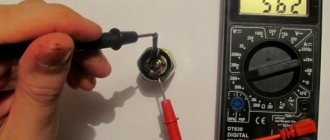
CHARGING THE CAPACITOR.
We assume that the capacitor is not initially charged. At time t = 0, the switch was closed, and a current flowed through the circuit, charging the capacitor. Increasing charges on the plates of the capacitor will increasingly impede the passage of current, gradually reducing it. Let's write Ohm's law for this closed circuit:
.
After separating the variables, the equation takes the form:
Integrating this equation taking into account the initial condition
q = 0 at t = 0 and taking into account the fact that when time changes from 0 to t, the charge changes from 0 to q, we obtain
, or after potentiation
q = . (4)
Analysis of this expression shows that the charge approaches its maximum value, equal to C, asymptotically at t ® ?.
Substituting the function I(t) = dq/dt into formula (4), we obtain
. (5)
From the law of conservation of energy it follows that when charging a capacitor for any moment in time, the work of the current source dAist is the sum of the amount of Joule heat dQ released on the resistor R and the change in the energy of the capacitor dW:
dAist = dQ + dW,
where dAist =Idt, dQ =I2Rdt, dW =d. Then for an arbitrary moment of time t we have:
Stork(t)===S. (6)
Q(t)==C. (7)
W(t) ==. (8)