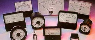
An electric motor is a machine that converts electrical energy into mechanical energy. Typically, mechanical work is expressed in the rotation of a shaft. These devices operate from different power sources and although they perform the same task, they have certain differences that determine their scope of application. It’s not for nothing that they put some motors in refrigerators, others in fans, and, in general, a third type in washing machines. For a better understanding, let’s look at the types of electric motors and how they differ from each other. This will help you understand the logic of choosing one or another engine for each device.
Types of electric motors: classification
There is no strict classification of electric motors, but they can be distinguished according to several parameters. The main ones are the type of power supply and the presence of a sliding contact. These positions can be considered key and easier to navigate. In general, there are not so many types of electric motors - synchronous, asynchronous, direct current, valve. That's probably all. Another thing is that in most “categories” there are enough options that significantly change the properties and characteristics. But this will have to be dealt with in relation to each design.
Electric motors differ in type of power supply, design and purpose
So, let's look at the types of electric motors based on the type of supply voltage. They are:
- direct current;
- AC: single phase power;
- three-phase power supply;
Only the universal type requires explanation. Such an electric motor can operate on both direct and alternating voltage. In fact, there is one type - a universal commutator motor with field windings. AC motors include synchronous and asynchronous. Collectors and valves operate on direct current.
The most common types of electric motors
According to the method of power transmission, all electric motors can be divided into two groups:
- with collector (brush);
- without a collector (brushless).
Brushless electric motors require less maintenance, are quieter, and more reliable. These include asynchronous with a squirrel-cage rotor (powered by alternating voltage), valve-type (powered by constant voltage). The rest have a commutator and brushes through which voltage is supplied to the coil windings.
Rewind
In order for an asynchronous electric motor to continue to perform its tasks at a high level, it is necessary to carefully monitor the condition of its stator windings. The most common method for eliminating identified problems is rewinding. But, as we have already written, first you should carry out an accurate inspection of copper components for breaks, abrasions and other damage. The most successful way to determine this is to test the stator coils of the power unit.
Calling
Most often, domestic electricians use a device such as a multimeter for this purpose. But before this, a visual inspection should be carried out. It is worth paying attention to the presence of external damage to the shell and insulation components, and areas where wires are burned during short circuits.
Stator continuity
The continuity test is quite simple - you need to check the resistance of each winding with an ohmmeter. They should be the same. It is also worth checking the housing by measuring the resistance on the housing. When testing insulation, it is still better to use a megohmmeter, which will provide more accurate measurement results.
Replacement
If no damage was detected during the measurements, the winding should be used further. But, if defects have nevertheless been identified, it is worth rewinding - replacing the copper elements of the stator.
It is carried out according to the following algorithm:
- dismantling the old winding and cleaning the channels from insulation residues;
- creating a circuit for a new stator coil with parameters similar to the previous one that failed;
- physical implementation of new winding, adhering to existing technological templates;
- monitoring of active stator components, laying copper elements;
- soldering copper elements according to the scheme implemented above;
- impregnation of the finished structure with varnish;
- drying.
General recommendations
When implementing the process of creating an updated winding and its further connection, you can adhere to the following recommendations:
- between the winding terminals and the housing, the resistance level should tend to the highest possible values;
- three-phase asynchronous electric motors must have the resistance of all windings at the same level;
- for single-phase modifications, the resistance indicators of the working windings should be an order of magnitude lower than those of the starting windings.
Rewinding stator windings
Benefits of rewinding
Implementation of updating the state of stator windings will extend the life of power units without significant damage to their performance.
Other benefits of doing this include:
- increase in specific power, which decreases during operation;
- efficiency and reliability. The component works without failures;
- possibility of uninterrupted duplication of windings, which greatly simplifies installation and further use.
It is also worth considering the high quality of the materials used, which also ensure the reliability of the winding.
Direct current
DC motors appeared at the end of the 19th century. With some modifications they are still used today and they are popular. For example, vibration in a modern smartphone is provided by a DC motor, very small and with a power of milliwatts, but still. Most toys also have such engines. But this does not mean that they are not used in serious technology, just as they are used. The most powerful ones are used as traction units on electric locomotives. Their power amounts to hundreds of kilowatts (more than 800), and they are powered by a voltage of 1.5 kV.
Types of DC motors
Collector
A commutator DC motor, like all others, consists of a stationary (stator) and a moving (armature) part. The stator has magnetic poles. For low-power models, permanent magnets are installed; for powerful ones, windings are added (called excitation windings), which enhance the magnetic field.
The rotor is a magnetic circuit made of metal plates, in the grooves of which turns of copper wire are laid - rotor windings. The ends of the rotor windings are brought out to the collector, which consists of copper plates in the form of cylinder sectors. The plates are isolated from each other and from the shaft on which they are mounted. The ends of the windings are brought out to the collector plates. The second part of the commutator unit is graphite brushes with a brush holder. The brushes are pressed against the commutator plates, but do not interfere with the rotation of the armature.
Commutator-type DC motor design
Voltage is applied to the brushes. At a certain point in time, they have contact with a certain pair of plates on the commutator (rarely there are four brushes). This pair of plates is connected to the rotor windings, that is, power is supplied to the winding through the brushes. A magnetic field arises around the armature, which interacts with the magnetic field of the stator. The resulting vector of this interaction “pushes” the armature, causing it to rotate.
The shaft rotates, the brushes contact another pair of plates, transferring potential to other windings, which pushes the armature further. This is how a brushed DC motor works, and in more detail in the previous article.
Universal
Most household appliances that operate on mains power use a universal commutator motor. Its differences from those described above are insignificant. How can the same design work on both direct and alternating voltage? This is all due to the fact that in this machine the magnetic fields of the poles and rotor windings interact. Everyone knows that changing the direction of rotation of the armature is simple: you need to change the polarity at the poles or at the rotor. What happens if you change them both here and there at once? Nothing. The anchor will continue to move in the same direction. This is the basis for the operation of a commutator electric motor running on alternating current.
Cross-section of a universal commutator motor
The field and armature windings are connected in series, so that the polarity of the power supply on them changes almost at the same time. The only thing that had to be changed in the universal engine was to make the armature core laminated. This is necessary to stabilize the interaction of the magnetic fields of the armature and poles (with the field windings).
Advantages, disadvantages, scope
Why are commutator motors used in most household and construction equipment? There are several reasons for this. First: they can accelerate to high speeds - up to 10 thousand rpm. Compared to 3 thousand rpm, which their closest competitors asynchronous develop, and this is very good. The second reason for their popularity is that they are easy to manage. The rotation speed directly depends on the applied voltage, and the torque on the armature current. Before the advent of semiconductors and the creation of frequency converters, this was the only type of electric motor that made it possible to easily and accurately control speed. The third reason for its widespread use is its simple design and relatively low price. Fourth, they can have good torque even at low speeds.
One of the popular types of electric motors is a commutator motor.
All these properties have determined a wide range of applications for DC motors. They are found on washing machines, drills, mixers, etc. Wherever high speeds are required, the ability to smoothly adjust, good torque.
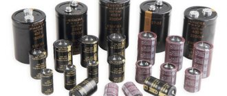
But the presence of brushes that spark and wear out makes its own adjustments. This unit requires constant maintenance; the brushes often have to be replaced and the commutator cleaned. In addition, it is the cause of two more unpleasant moments. The first is noisy work. For construction equipment or industrial equipment this may not be very critical, but for household equipment it is a significant disadvantage. The second trouble is that the brushes jump from one pair to another, so the current consumption turns out to be pulsed, which has a bad effect on the power parameters and creates radio interference. This has an impact on radio-controlled devices operating nearby. These are not only toys, but also various types of remote controls. To smooth out these jumps, capacitors are placed at the input; they smooth out the ripples and remove interference.
Valve motors
These motors are also called switched reluctance motors, brushless motors or brushless motors. There are two types of valve motors - “regular” and self-excited. Moreover, they differ in structure and functions.
Fan motors, regardless of type, are electronically controlled
Switched reluctance motor
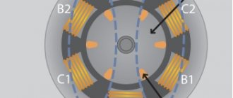
If we compare types of electric motors by size, valve motors will be the smallest. What is typical is that they operate from direct current, and the stator windings are powered by it; the rotor does not have windings, but is made of permanent magnets. Moreover, both the rotor and stator have a gear structure. The “kit” includes a hall sensor, a small modern controller that detects the position of the rotor and, depending on its position, supplies power to one or another pair of windings on the stator. That is, the valve motor is controlled using an electronic device.
Design of a brushless electric motor
The principle of operation is probably already clear. Power is supplied to one pair of windings, and a magnetic field appears around it. The nearest pole of the magnet is attracted to this field. Next, the power switches to the next pair of windings, and the magnet is attracted there. This is how the rotor rotates. The faster the power switches, the faster the rotor speed. As you can see, no brushes, only magnetic induction. This is the main plus, and the minus is the “pulsating” nature of the torque. Therefore, switched induction motors are not used in transport; few people will like it if the wheels turn jerkily. Nevertheless, considering these types of electric motors, we come to the conclusion that this one has four significant advantages: simplicity of design, good speed control, absence of a commutator, and the fourth - small dimensions. All this allows them to replace asynchronous engines in some cases.
With independent excitation
This type of electric motor is worth highlighting separately, since it differs significantly both in design, characteristics and scope of application. Let's start with the fact that the rotor consists of two separate magnetic packages, spaced at some distance from each other. The poles of the two packages are oriented so that the resulting torque is zero (matched position). The field winding is attached to the stator, although it is wound around the rotor, but it does not touch it. The stator magnetic system is also assembled from metal plates. Three-phase distributed in nature, three phase windings offset relative to each other by 120°. The stator winding is slightly larger or equal in size to the assembled rotor (both packages are covered by a magnetic field).
Self-excited switched induction electric motor
Power is supplied to one of the stator windings. The induced field in the rotor rotates it to match the stator field. Moreover, the field is simultaneously induced in two packets, so the movement is not as jerky as in the previous model. The power switches to the next winding and rotation continues.
What is good about this type of electric motor? There are many advantages. It is easy to control the rotation speed, like synchronous machines with an excitation winding, vector control is available. You can increase or decrease the speed, adjust the torque. It does not contain magnets, which cost a lot and can even become demagnetized. And one more plus, there is no commutator or brushes. There is still a minus. This type of electric motor cannot be powered directly from the network - a converter is required. And yet, it has a more complex design than the option described above. But the torque is smoother and almost linear.
Engine Minato
Another striking example of the use of magnetism energy for self-excitation and autonomous operation is today a serial model developed more than thirty years ago by the Japanese Kohei Minato. It is distinguished by noiselessness and high efficiency. According to Minato's own statements, a self-rotating magnetic motor of this design has an efficiency above 300%.
Engine Minato
The rotor has the shape of a disk or wheel, on which magnets are located at a certain angle. When a stator with a large magnet is brought to them, a moment arises and the Minato wheel begins to rotate, using alternating approach and repulsion of the poles. The closer the stator is to the rotor, the higher the torque and rotation speed. Power is supplied through the breaker relay circuit.
To prevent impulses and beating when the Minato wheel rotates, stabilizer relays are used and the control current consumption is minimized. magnet The disadvantage can be considered the lack of data on the load characteristics, traction, used control circuit relays, as well as the need for periodic magnetization, about which, by the way, there is also no information from Minato.
It can be assembled, like other prototypes, experimentally, from improvised means, for example, construction parts, relays, electrical components. magnets, etc.
Alternating current
AC electric motors are either synchronous or asynchronous. How are these types of electric motors different? The difference is that in synchronous models the rotor rotates at the same speed with which the stator field changes; in asynchronous models the rotor speed is different.
There are two types of AC motors - with synchronous and asynchronous rotor rotation
AC induction motor
In devices that are powered from a three-phase network, asynchronous motors are usually installed. So, they are the ones in production. These machines have a separate electromagnetic system in the stator. Plates are inserted inside the housing, in the grooves of which the phase windings are located. Usually there are three phases in the stator, but there may be two, or maybe many.
The rotor can be of two types - squirrel-cage or phase. The short-circuit can be all-metal (latest models) or consist of a “squirrel” cage with aluminum-filled spaces between the cage rods. The rotor is inserted into the stator, leaving a minimum gap between them, no more than a couple of millimeters even for the most powerful ones. A voltage is applied to the stator, which forms a rotating magnetic field. The rotor enters the zone of action of the magnetic field, and currents are induced in it. The resulting field has a certain direction, so that the rotor begins to rotate. Since the field arises by induction, there is no electrical contact between the rotor and the stator, there is no commutator and brushes. The shaft is fixed only in the stator covers on bearings. This motor belongs to the brushless (brushless) group.
Asynchronous motor with different rotors
An asynchronous motor with a wound rotor has a commutator unit. A magnetic circuit made of stacked plates with cells for three phase windings is put on the shaft. Power is supplied to the windings through the collector unit, and a magnetic field alternately appears in them, which is combined with the magnetic field of the stator. Thanks to this, rotation occurs.
Features of single-phase models
In a single-phase asynchronous motor, there are two windings in the stator: one is phase, the second is auxiliary or starting. It is needed to “accelerate” the rotor in order to give it initial rotation. To ensure the “lag”, the starting winding is turned on through a capacitor. So this type of asynchronous motor is often called a capacitor motor. Although, in essence, the motor is still the same asynchronous, but two-phase.
Such motors cannot develop sufficient torque, so they are used where it is not required, for example in exhaust fans. Other types of electric motors are not used in this area, since high torque is unnecessary.
Advantages, disadvantages, scope
As already mentioned, asynchronous motors are popular and mainly models with a squirrel-cage rotor. There are several advantages. The first is that there is no collector, which simplifies the design; the motor requires simpler and less frequent maintenance. Secondly, they can be connected to the network directly. During start-up, current consumption increases greatly (3-7 times compared to the nominal value), but such overloads are acceptable. Third, the design is simple and therefore inexpensive.
The scope of application of asynchronous motors is industrial processes, equipment. Especially where there is no need for high speeds and speed changes. The maximum speed that such an engine can develop is 3 thousand rpm. Not much, but enough equipment for most people. The speed of such an engine is poorly regulated. You can lower the voltage and the speed will decrease. But if the voltage is too low, the lag between the rotor speed and the speed of the magnetic field will increase, which will lead to overheating and the motor may burn out.
The scope of application of AC motors is to drive equipment in production
The problem of speed control of asynchronous motors has now been solved. They are used in conjunction with frequency converters, supplying voltage from them, or this unit is built into the structure, producing so-called inverter motors. In most cases, these are asynchronous systems, powered by a built-in converter. This allows you to change the speed within even wider limits than a DC motor allows. Moreover, the torque can also be adjusted, the problem of starting currents goes away, and the engine can also be turned off “softly”.
Synchronous electric motors
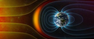
The stator of a synchronous AC motor is made in almost the same way as an asynchronous one. The difference between them is the rotor design. It consists of permanent magnets. They can be fixed to the surface or built inside. So the types of electric motors, synchronous and asynchronous, can be distinguished by the rotor.
When power is applied to the stator windings, a rotating magnetic field is created. The magnetic field of the rotor is constant and when they interact, a torque arises, which “pushes” the rotor. During operation, the constant field of magnets on the rotor “couples” with the rotating magnetic field of the stator, therefore their rotation speeds are the same and the rotor speed is easy to control. But this phenomenon makes starting difficult. The rotor will “couple” with the stator field only if it has the same speed.
The rotor of a DC synchronous motor is made of magnets
Synchronous electric motors have one problem - they are difficult to start. The rotor rotation speed must be equal to the stator field speed either this way or not at all. Right away, from the start, it simply cannot develop such a speed, because the stator field simply “slides.” As a result, the rotor simply shakes when starting, but does not rotate. They say the engine is “out of sync.” The problem is usually solved by installing a special asynchronous type starting winding on the rotor. With its help, the shaft accelerates, then the starting winding is turned off, and the constant field of magnets synchronizes the rotation speed.
Advantages, disadvantages, application
As you probably already understood, the speed of a synchronous motor is not regulated in any way. I mean, you can change the speed of the stator magnetic field, and it depends on the frequency. Before the invention of semiconductor devices, this was difficult, troublesome and ineffective. Despite the stability of operation and simplicity of design, they were rarely used. First of all, it's difficult to start; secondly, there is no way to regulate the speed. Other types of electric motors were more popular.
With the invention of the frequency converter, the problem disappeared. With their help, the frequency of three-phase current can be changed from 1 Hz to 500 Hz, so the adjustment limits of an asynchronous motor can also be more than significant. Moreover, the characteristics of this “pair” are almost the same as those of DC motors. Therefore, now synchronous motors with frequency converters are actively replacing other types of electric motors, for example, they are installed instead of a commutator drive. An example of this is direct drive washing machines and cooling coolers. DC motors also began to be replaced, and new electric trains with synchronous motors and frequency converters appeared.
Energy conversion principle
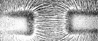
The operating principle of any type of electric motor is to use electromagnetic induction that occurs inside the device after being connected to the network. In order to understand how this induction is created and sets the engine elements in motion, you should turn to a school physics course that explains the behavior of conductors in an electromagnetic field.
So, if we immerse a conductor in the form of a winding, along which electric charges move, into a magnetic field, it will begin to rotate around its axis. This is due to the fact that the charges are under the influence of a mechanical force that changes their position on a plane perpendicular to the magnetic field lines. We can say that the same force acts on the entire conductor.
The diagram below shows a current-carrying loop that is energized and two magnetic poles that give it rotational motion.
The picture is clickable.
It is this pattern of interaction between the magnetic field and the current-carrying circuit with the creation of electromotive force that underlies the functioning of electric motors of all types. To create similar conditions, the device design includes:
- Rotor (winding) is a moving part of the machine, mounted on a core and rotation bearings. It plays the role of a current-conducting rotational circuit.
- The stator is a stationary element that creates a magnetic field that affects the electric charges of the rotor.
- Stator housing. Equipped with mounting sockets with cages for rotor bearings. The rotor is placed inside the stator.
To represent the design of an electric motor, you can create a circuit diagram based on the previous illustration:
After connecting this device to the network, a current begins to flow through the rotor windings, which, under the influence of the magnetic field arising on the stator, gives the rotor rotation, which is transmitted to the rotating shaft. Rotation speed, power and other performance indicators depend on the design of the specific motor and the parameters of the electrical network.
Types of electric motors: which one is better
Only the main types of electric motors are described and brief characteristics are given; the device and principle of operation are described very briefly. However, it is already possible to draw conclusions that there is simply no ideal solution for all cases. There is one that is most suitable for each specific case.
- An asynchronous electric motor without frequency regulation is the best choice for pumps.
- The commutator motor with its variable speeds is unrivaled for drills and vacuum cleaners. And then, recently they began to do it with valve-type ones, they are without brushes, which makes the work quieter, the service life is longer, although the price is higher. So, here's how to look.
You need to choose the type of electric motor for each specific case.
- For fans with long-term operation, you have to choose between asynchronous and valve ones. But only if they are not too powerful. For powerful ones, the ability to divide into sections is important, and this is easier to implement with valve-type ones. And even on coolers they have recently begun to use valve coolers with a magnetic rotor.
In general, to answer which one is better, we need to consider the totality of the conditions and characteristics of the work. Take into account the advantages and disadvantages, go through all types of electric motors, and this is the only way to find the optimal one.
Lazarev engine
Lazarev engine design
Domestic developer Nikolai Lazarev has created a working and fairly simple version of the unit using magnetic traction. Its engine, or rotary ring, consists of a container divided by a porous flow barrier into upper and lower parts. They communicate with each other through a tube through which a flow of water/liquid flows from the lower chamber to the upper one. In turn, the pores provide gravitational downward flow. If you place a wheel under the flow of liquid, on the blades of which magnets are attached, you will be able to achieve the goal of the flow - rotation and creation of a constant magnetic field. The rotary engine diagram of Nikolai Lazarev is used to calculate and assemble the simplest self-rotating devices.
Aircraft devices
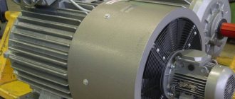
The operation of engines of this type is based on the principle of electromagnetic induction. For this purpose, stators are used of a three-pole type. Also, electromagnetic aircraft engines include brushless commutators. Terminal boxes in devices are located above the slip rings. An integral part of the stator is the armature. The shaft rotates thanks to roller bearings. Some modifications use brush holders. It is also important to mention the different types of terminal boxes. In this case, a lot depends on the power of the modification. Electromagnetic engines for aircraft are equipped with fans for cooling purposes.
Motor stator
The stator is the stationary electrical component of an electric motor. It includes several windings, the polarity of which constantly changes as alternating current (AC) passes through them. Thus, a combined stator magnetic field is created.
All stators are installed in a frame or housing. The stator housing of Grundfos electric motors for electric motors up to 22 kW is most often made of aluminum, and for electric motors with higher power - from cast iron. The stator itself is installed in the stator housing. It consists of thin plates of electrical steel wrapped in insulated wire. The core consists of hundreds of such plates. When power is applied, alternating current passes through the windings, creating an electromagnetic field perpendicular to the rotor conductors. Alternating current (AC) causes the magnetic field to rotate.
The stator insulation must comply with the requirements of IEC 62114, which provides different protection classes (temperature levels) and temperature change (AT). Grundfos electric motors have protection class F, and when the temperature rises - class B. Grundfos produces 2-pole electric motors with power up to 11 kW and 4-pole electric motors with power up to 5.5 kW. Grundfos purchases more powerful electric motors from other companies whose product quality meets Grundfos standards. For pumps, stators with two, four and six poles are mainly used, since the speed of the electric motor shaft determines the pressure and flow of the pump. The stator can be manufactured to handle different voltages, frequencies and output powers, as well as a variable number of poles.
Brushless modifications
Brushless modifications are not common these days. They are used for ventilation systems. Their distinctive feature is considered to be noiselessness. However, it should be taken into account that the models are produced with low power. On average, this parameter does not exceed 12 kW. The stators in them are often installed of a two-pole type. The shafts used are short. Special seals are used to enclose the rotor. Sometimes engines are enclosed in a casing that has ventilation ducts.
Brief overview of famous designs
Among the large number of magnetic motor designs, the following can be distinguished:
- Kalinin magnetic type motors. The design is completely inoperable, since the spring compensator mechanism has not been completed.
- Magnetic-mechanical motor designed by Dudyshev. If properly tuned, such engines can operate almost forever.
- “Perendev” are electromagnetic motors made according to the classical design. A compensator is installed on the rotor, but it is not capable of operating without switching when passing the dead center. And in order for the rotor to pass the holding dead point, switching can be done in two ways - using an electromagnet and a mechanical device. Such a design cannot claim the title of “perpetual motion machine”. And even a simple asynchronous motor will have a much higher electromagnetic torque.
- Electromagnetic motors designed by Minato. Made according to the classical scheme, it is a conventional electromagnetic motor, which has a very high efficiency. Taking into account the fact that the design cannot achieve 100% efficiency, it does not work as a “perpetual motion machine”.
- Johnson motors are analogues of Perendev, but they have less energy.
- Shkondin motor-generators are a structure that operates using the force of magnetic repulsion. Compensators are not used in motors. They are not capable of operating in “perpetual motion” mode; the efficiency is no more than 80%. The design is very complex, since it contains a commutator and a brush assembly.
- The most advanced mechanism is the Adams-designed motor-generator. This is a very well-known design, it works on the same principle as the Shkodin motor. But unlike the latter, repulsion occurs from the end of the electromagnet. The design of the device is much simpler than that of Shkondin. The efficiency can be 100%, but only if the electromagnet winding is switched using a short pulse with high intensity from a capacitor. It cannot work in “perpetual motion” mode.
- Reversible electromagnetic motor. The magnetic rotor is located outside, and a stator made of electromagnets is installed inside. The efficiency is close to 100%, since the magnetic circuit is open. Such an electromagnetic solenoid motor is capable of operating in two modes - motor and generator.
Placement category and climatic version
All electric motors are manufactured taking into account the impact of certain environmental factors during operation. For this reason, all electrical machines are divided into the following placement categories:
- For rooms with high humidity levels.
- For closed premises with natural ventilation without artificial regulation of climatic parameters. At the same time, exposure to dust, moisture and UV radiation is limited.
- In open space conditions.
- For closed premises with artificial regulation of climatic parameters. At the same time, exposure to dust, moisture and UV radiation is limited.
- For rooms with changes in humidity and temperature that do not differ from changes outside.
Depending on the climatic design in accordance with the requirements of GOST 15150 - 69, all electric motors are divided into the following types of design:
- All possible macroclimatic regions (B).
- Cold (HL).
- All sea areas (OM).
- Dry tropical (TC).
- General (O).
- Moderate (U).
- Temperate marine (M).
- Wet Tropical (TV).
The placement category and climatic modification are indicated in the symbol of the electric motor on its tag and in the passport.
Synchronous devices
The synchronous motor circuit includes a two-pole stator as well as a brush commutator. Some devices use a magnetic circuit. If we consider household modifications, they use brush holders. The average power parameter is 30 kW. Devices with fans are rare. Some models use gear drives.
To cool the engine, there are ventilation holes on the casing. In this case, the retaining ring is installed at the base of the shaft. The winding is of low voltage type. The operating principle of synchronous modification is based on the induction of an electromagnetic field. To do this, magnets of different power are installed in the stator. When the winding is excited, the shaft begins to rotate. However, its frequency is low. Powerful models have collectors with relays.
Parallel Excitation Models
Electromagnetic motors of this type are made on the basis of brush commutators. There are no anchors in this case. The shaft in the devices is mounted on roller bearings. Also, special paws are used to reduce the friction force. Some configurations have magnetic cores. Models can only be connected to a DC network.
It is also important to note that the market mainly consists of three-stroke modifications. The brush holders in the devices are made in the form of cylinders. The models differ in power. On average, the operating current at idle does not exceed 50 A. To enhance the electromagnetic field, rotors with high-voltage windings are used. Some configurations use tips on magnetic cores.
Patents for electromagnetic machines
Many engineers have already patented their engine designs. But no one has yet been able to implement a workable perpetual motion machine. Such devices have not yet been mastered, are rarely introduced into technology, and are unlikely to be found on sale. Solenoid valves are used much more often (diesel engines operate more stably under electronic control and are capable of delivering more power). Some designers are confident that electromagnetic motors are not brought to serial production because all developments are classified. And most of the problems in such engines have not yet been completely resolved.