Details Category: Beginners
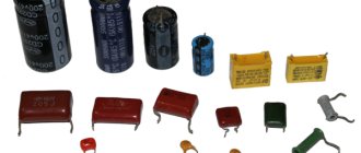
It is very important to know the capacitance of a particular capacitor, and measuring instruments with which you can find out this capacitance are not always at hand. Code markings were invented especially for these cases. There are 4 main ways of marking capacitors :
- Code marking with 3 digits;
- Code marking with 4 digits;
- Alphanumeric marking;
- Special markings for planar capacitors.
What is a capacitor?
A device that stores electricity in the form of electrical charges is called a capacitor.
The amount of electricity or electric charge in physics is measured in coulombs (C). Electrical capacitance is calculated in farads (F).
A solitary conductor with an electrical capacity of 1 farad is a metal ball with a radius equal to 13 radii of the Sun. Therefore, a capacitor includes at least 2 conductors, which are separated by a dielectric. In simple device designs, paper is used.
The operation of a capacitor in a DC circuit is carried out when the power is turned on and off. Only during transient moments does the potential on the plates change.
The capacitor in the AC circuit recharges at a frequency equal to the frequency of the power source voltage. As a result of continuous charges and discharges, current flows through the element. A higher frequency means the device recharges faster.
The resistance of the circuit with a capacitor depends on the frequency of the current. At zero frequency of direct current, the resistance value tends to infinity. As the AC frequency increases, the resistance decreases.
Operating principle of capacitors
When a circuit is connected to an electrical source, electrical current begins to flow through the capacitor. At the beginning of the passage of current through the capacitor, its strength is at its maximum and the voltage is at its minimum. As the device accumulates charge, the current drops until it disappears completely, and the voltage increases.
During the process of charge accumulation, electrons accumulate on one plate and positive ions on the other. Charge does not flow between the plates due to the presence of a dielectric. This is how the device accumulates charge. This phenomenon is called the accumulation of electric charges, and the capacitor is called an electric field accumulator.
Characteristics and properties
Capacitor parameters that are used to create and repair electronic devices include:
- Capacity - C. Determines the amount of charge that the device holds. The value of the nominal capacity is indicated on the case. To create the required values, the elements are included in the circuit in parallel or in series. Operational values do not coincide with calculated values.
- Resonant frequency - fр. If the current frequency is greater than the resonant one, then the inductive properties of the element appear. This makes work difficult. To ensure the design power in the circuit, it is reasonable to use a capacitor at frequencies below resonant values.
- Rated voltage - Un. To prevent breakdown of the element, the operating voltage is set less than the rated voltage. The parameter is indicated on the capacitor body.
- Polarity. If the connection is incorrect, breakdown and failure will occur.
- Electrical insulation resistance - Rd. Determines the leakage current of the device. In devices, parts are located close to each other. At high leakage current, parasitic connections in the circuits are possible. This leads to malfunctions. Leakage current worsens the capacitive properties of the element.
- Temperature coefficient - TKE. The value determines how the capacitance of the device changes with fluctuations in ambient temperature. The parameter is used when developing devices for operation in harsh climatic conditions.
- Parasitic piezoelectric effect. Some types of capacitors create noise in devices when deformed.
Types of markings
At the moment, manufacturers use several types, which can be located on the body either individually or interchangeably. All values below will be purely theoretical, provided for illustrative purposes.
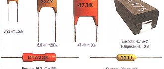
The simplest type of marking - no codes or table substitutions, the capacity is directly written on the body, which immediately provides the end user with real parameters without unnecessary movements. And this method would be used everywhere, if not for its bulkiness - it will be possible to completely write the container only on fairly large products, otherwise it will be impossible to see the inscription even with a magnifying glass. For example: writing 100 µF±6% means that this capacitor has a capacitance of 100 microfarads with a damping of 6% of the total capacitance, which is equal to a value of 94-106 microfarads. It is also possible to use markings of the form 100 µF +8%/-10%, which means unequal damping equal to 90–108 microfarads. This is the simplest and most understandable method, however, such marking is very cumbersome, so it is used on large and very capacitive capacitors.
Marking of large products
Digital marking of capacitors (as well as numerical and alphabetic markings) is used in cases where the small area of the product does not allow a detailed record of the capacitance to be placed. Therefore, certain values are replaced with ordinary numbers and Latin letters, which are deciphered one by one to obtain complete information.
Numerical and alphanumeric markings of small capacitors
Everything is very simple - if only numbers are used (and on such products there are usually three of them), then you need to decipher them as follows:
- the first two digits indicate the first two digits of the capacity;
- the third digit indicates the number of zeros that must be added after the first two digits;
- such capacitors are always measured in picofarads.
Let's take for example the first option from the picture above with the entry 104. We leave the first two digits as 10. To them we add the number of zeros indicated by the third digit, that is, 4. We get a value of 100,000 picofarads. We return to the table at the beginning of the article, reduce the number of zeros and get an acceptable value of 100 microfarads.
If one or two digits are used, they remain that way. For example, the notations 5 and 15 represent 5 and 15 picofarads, respectively. The .55 marking is equal to 0.55 microfarads.
An interesting notation is made using letters either instead of a dot or as another quantity. For example, 8n2 means 8.2 nanofarads, while n82 means 0.82 nanofarads. For a certain class of capacitors, an additional code marking may be added at the end, for example, 100V.
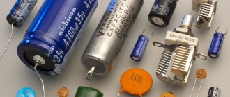
Labeling of ceramic capacitors using a numerical and alphabetic method is the standard for these products. Here, exactly the same encryption algorithms are used, and the inscriptions themselves are physically applied by the manufacturer to the ceramic surface.
Ceramic capacitors with markings
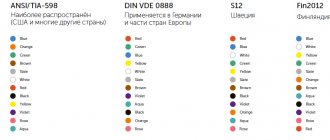
- An outdated, but still used option is color indication. It was used in Soviet production to simplify the reading of markings even on very small products. The downside is that it is quite problematic to remember such a table right away, so it is advisable to have it on hand, at least at first. The colors are applied to the capacitors, where the marking is done in the form of monotonous stripes. Read as follows: the first two colors indicate the capacitance in picofarads;
- the third color shows the number of zeros that need to be added;
- the fourth and fifth colors respectively show the possible tolerance and nominal voltage supplied to the product.
| Color | Meaning |
| Black | |
| Brown | 1 |
| Red | 2 |
| Orange | 3 |
| Yellow | 4 |
| Green | 5 |
| Blue | 6 |
| Violet | 7 |
| Grey | 8 |
| White | 9 |
Marking of imported capacitors is carried out in similar ways, only the Latin alphabet can be used instead of Cyrillic. For example, on domestic versions there may be 5mk1, which means 5.1 microfarads. Whereas on imported ones this value will look like 5µ If the entry is completely incomprehensible, then you can contact the official manufacturer for clarification; most likely, the website has tables or a program that decipher its markings. However, this occurs only in exceptional cases and is rarely encountered.
Marking of capacitors with a linear dependence on temperature
Table 3
| GOST designation | International designation | TKE [ppm/°C]* | Letter code | Color** |
| P100 | P100 | 100 (+130…-49) | A | red+purple |
| P33 | 33 | N | grey | |
| MPO | NPO | 0(+30..-75) | WITH | black |
| M33 | N030 | -33(+30…-80] | N | brown |
| M75 | N080 | -75(+30…-80) | L | red |
| M150 | N150 | -150(+30…-105) | R | orange |
| M220 | N220 | -220(+30…-120) | R | yellow |
| M330 | N330 | -330(+60…-180) | S | green |
| M470 | N470 | -470(+60…-210) | T | blue |
| M750 | N750 | -750(+120…-330) | U | violet |
| M1500 | N1500 | -500(-250…-670) | V | orange+orange |
| M2200 | N2200 | -2200 | TO | yellow+orange |
* The actual spread for imported capacitors in the temperature range -55...+85°C is shown in brackets.
** Modern color coding according to EIA. Colored stripes or dots. The second color can be represented by the color of the body.
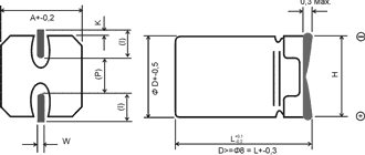
Code marking of electrolytic capacitors for surface mounting
The following coding principles are used by such well-known companies as Hitachi and others. There are three main coding methods:
A. Marking with 2 or 3 characters
The code contains two or three characters (letters or numbers) indicating the operating voltage and rated capacity. Moreover, the letters indicate voltage and capacitance, and the number indicates the multiplier. In the case of a two-digit designation, the operating voltage code is not indicated.
Rice. 9
Table 14
| Code | Capacity | Voltage |
| A6 | 1,0 | 16/35 |
| A7 | 10 | 4 |
| AA7 | 10 | 10 |
| AE7 | 15 | 10 |
| AJ6 | 2,2 | 10 |
| AJ7 | 22 | 10 |
| AN6 | 3,3 | 10 |
| AN7 | 33 | 10 |
| AS6 | 4,7 | 10 |
| AW6 | 6,8 | 10 |
| CA7 | 10 | 16 |
| CE6 | 1,5 | 16 |
| CE7 | 15 | 16 |
| CJ6 | 2,2 | 16 |
| CN6 | 3,3 | 16 |
| CS6 | 4,7 | 16 |
| CW6 | 6,8 | 16 |
| DA6 | 1,0 | 20 |
| DA7 | 10 | 20 |
| DE6 | 1,5 | 20 |
| DJ6 | 2,2 | 20 |
| DN6 | 3,3 | 20 |
| DS6 | 4,7 | 20 |
| DW6 | 6,8 | 20 |
| E6 | 1,5 | 10/25 |
| EA6 | 1,0 | 25 |
| EE6 | 1,5 | 25 |
| EJ6 | 2,2 | 25 |
| EN6 | 3,3 | 25 |
| ES6 | 4,7 | 25 |
| EW5 | 0,68 | 25 |
| GA7 | 10 | 4 |
| GE7 | 15 | 4 |
| GJ7 | 22 | 4 |
| GN7 | 33 | 4 |
| GS6 | 4,7 | 4 |
| GS7 | 47 | 4 |
| GW6 | 6,8 | 4 |
| GW7 | 68 | 4 |
| J6 | 2,2 | 6,3/7/20 |
| JA7 | 10 | 6,3/7 |
| JE7 | 15 | 6,3/7 |
| JJ7 | 22 | 6,3/7 |
| JN6 | 3,3 | 6,3/7 |
| JN7 | 33 | 6,3/7 |
| JS6 | 4,7 | 6,3/7 |
| JS7 | 47 | 6,3/7 |
| JW6 | 6,8 | 6,3/7 |
| N5 | 0,33 | 35 |
| N6 | 3,3 | 4/16 |
| S5 | 0,47 | 25/35 |
| VA6 | 1,0 | 35 |
| VE6 | 1,5 | 35 |
| VJ6 | 2,2 | 35 |
| VN6 | 3,3 | 35 |
| VS5 | 0,47 | 35 |
| VW5 | 0,68 | 35 |
| W5 | 0,68 | 20/35 |
We advise you to study the Do-it-yourself cable cutting machine
Rice. 10
B. 4-character marking
The code contains four characters (letters and numbers) indicating the capacity and operating voltage. The first letter indicates the operating voltage, the subsequent digits indicate the nominal capacitance in picofarads (pF), and the last digit indicates the number of zeros. There are 2 options for encoding the capacity: a) the first two digits indicate the nominal value in picofarads, the third - the number of zeros; b) the capacitance is indicated in microfarads, the m sign acts as a decimal point. Below are examples of marking capacitors with a capacity of 4.7 μF and an operating voltage of 10 V.
Rice. eleven
C. Two-line marking
If the size of the case allows, then the code is located in two lines: the capacitance rating is indicated on the top line, and the operating voltage is indicated on the second line. Capacitance can be indicated directly in microfarads (µF) or in picofarads (pf) indicating the number of zeros (see method B). For example, the first line is 15, the second line is 35V - means that the capacitor has a capacity of 15 uF and an operating voltage of 35 V.
Rice. 12
Marking of planar electrolytic capacitors
There are two main ways to mark such capacitors:
- Alphanumeric. Example: 10 3.3V which corresponds to 10uF and 3.3 Volts.
- According to the code. Example: G101 where G is the voltage according to the table, and 101 is 10*101 which corresponds to 100pF.
| Letter | e | G | J | A | C | D | E | V | H (T for tantalum) |
| Voltage | 2.5 V | 4 V | 6.3 V | 10 V | 16 V | 20 V | 25 V | 35 V | 50 V |
- < Back
- Forward >
Comments
ololosh 12/22/2015 20:56
Quote
mihan 03/12/2016 16:24 Thank you! Now everything fell into place; for a long time I could not figure out the markings of the capacitors.
Quote
Alexandr 11.12.2016 12:00 Tell me please. What is taken from here https://prnt.sc/dhzjl2 https://prnt.sc/dhzjf9 This is an ancient nvidia 9800gt video card
Quote
Update list of comments
Application
Capacitors are used in almost all areas of electrical engineering. Let's list just a few of them:
- construction of feedback circuits, filters, oscillatory circuits;
- use as a memory element;
- for reactive power compensation;
- to implement logic in some types of protection;
- as a sensor for measuring liquid level;
- for starting electric motors in single-phase AC networks.
Using this radio-electronic element, it is possible to receive high-power pulses, which is used, for example, in photo flashes and in the ignition systems of carburetor engines.
Designation in diagrams
In general, when repairing and re-soldering modern SMD printed circuit boards, it is most convenient when you still have a diagram at hand, looking at which it is much easier to understand what is installed, to find out the location of a certain part, because an SMD capacitor in appearance may not differ at all from the same transistor. The designations of these parts in the circuits remained the same as they were before the arrival of chips on the market, and therefore the capacity and other necessary characteristics can also be easily found by a radio amateur who has not encountered SMD components.
Video
How to choose a capacitor
Green Glade picnic set for 4 persons.
4309 ₽ More details
Green Glade picnic set for 4 persons.
4300 ₽ More details
Women's plus size sneakers
Marking SMD capacitors.
The dimensions of SMD capacitors are small, so their marking is done very succinctly. The operating voltage is often coded by letter (2nd and 3rd options in the figure below) in accordance with the data provided in the previous section. The nominal capacity can be encoded either using a three-digit digital code (option 2 in the figure) or using a two-digit alphanumeric code (option 1 in the figure). When using the latter, you can still find two (and not one letter) with one number on the case (option 3 in the figure).
The first letter can be either a manufacturer's code (which is not always interesting) or indicate the rated operating voltage (more useful information), the second can be an encoded value in picoFarads (mantissa). The number is an exponent (indicates how many zeros need to be added to the mantissa). For example, EA3 may mean that the rated voltage of the capacitor is 16V(E) and the capacitance is 1.0 * 1000 = 1 nanofarad, BF5, respectively, the voltage is 6.3V(V), the capacitance is 1.6 * 100000 = 0.1 microfarad and. etc.
Marking of planar ceramic capacitors
Such capacitors are marked with two letters, the first is the manufacturer of the capacitor, and the second is the value in picofarads in accordance with the table below.
| Marking | Meaning | Marking | Meaning | Marking | Meaning | Marking | Meaning |
| A | 1.0 | J | 2.2 | S | 4.7 | a | 2.5 |
| B | 1.1 | K | 2.4 | T | 5.1 | b | 3.5 |
| C | 1.2 | L | 2.7 | U | 5.6 | d | 4.0 |
| D | 1.3 | M | 3.0 | V | 6.2 | e | 4.5 |
| E | 1.5 | N | 3.3 | W | 6.8 | f | 5.0 |
| F | 1.6 | P | 3.6 | X | 7.5 | m | 6.0 |
| G | 1.8 | Q | 3.9 | Y | 8.2 | n | 7.0 |
| H | 2.0 | R | 4.3 | Z | 9.1 | t | 8.0 |
Why is labeling needed?
The purpose of marking electronic components is to allow them to be accurately identified. Capacitor markings include:
- data on the capacitance of the capacitor - the main characteristic of the element;
- information about the rated voltage at which the device remains operational;
- data on the temperature coefficient of the capacitance, which characterizes the process of changing the capacitance of the capacitor depending on changes in ambient temperature;
- percentage of permissible deviation of the capacity from the nominal value indicated on the device body;
- release date.
For capacitors, when connecting which polarity must be observed, information must be provided that allows the element to be correctly oriented in the electronic circuit.
The marking system for capacitors produced at enterprises that were part of the USSR had fundamental differences from the marking system used at that time by foreign companies.
Marking of solid capacitors
According to the international standard, they begin to read from units of measurement. Farads are used to measure capacitance. The marking is applied to the body of the device itself.
Sometimes markers are applied that indicate permissible deviations from the norm of the capacitance of the capacitor itself (indicated as a percentage).
Sometimes, instead of them, a letter is used that denotes one or another value of the tolerance itself. Then we determine the rated voltage. In the event that the device body is large, this parameter is indicated by a number, followed by letters. The maximum permissible value of the parameter is indicated using numbers. If there is no information on the housing about the permissible voltage value, then it can only be used in low-voltage circuits. If the device, according to its parameters, should be used in circuits where there is alternating current, then it, accordingly, should be used exactly this way and not otherwise.
A device that operates with direct current cannot be used in circuits with alternating current.
Next, we determine the polarity of the device: positive and negative. This step is very important. If the poles are determined incorrectly, there is a high risk of a short circuit or even explosion of the device itself. Regardless of the polarity, the capacitor can be connected if no information about the plus and minus terminals is indicated.
The polarity value can be applied in the form of special indentations that have the shape of a ring, or in the form of a single-color stripe. In aluminum capacitors, which in appearance resemble a can of cans, such designations indicate negative polarity. But, for example, in tantalum capacitors, which have small dimensions, the opposite is true - the polarity with these designations will be positive. Color coding should not be taken into account only if plus and minus are indicated on the capacitor itself.
Capacitor markings: explanation
The values of the first two digits on the case, which indicate the capacity of the device. If the capacitor is small, marking is carried out according to the EIA standard.
Numbers: designation
When the designation contains only one letter and two numbers, the numbers correspond to the capacitance parameter of the capacitor. You need to decipher the remaining markings in your own way, based on one or another instruction. The zero multiplier is the third digit. Decoding is carried out depending on what number is at the end. A certain number of zeros must be added to the first two digits if the digit is in the range from zero to six. If the last digit is the number eight, then in this case it is necessary to multiply the first two digits by 0.01. When the value of the capacitance of the capacitor becomes known, it will be necessary to determine the units of measurement in which this value is indicated. Ceramic devices, as well as film options, are small. In them, this parameter is measured in picofarads. Microfarads are used for large capacitors.
Letters: their designation
Next, you need to decipher the letters that are in the marking. If there is a letter in the first two characters, then it can be deciphered using several methods. If there is a letter R, then it plays the role of a comma, which is used in a fraction. If there are letters u, n, p, then it also acts as a comma in the same fraction.
Ceramic capacitors: marking
These types of devices have two contacts and a round shape. Both the main indicators and the tolerance for deviations from the capacity parameter will be indicated on the case. To do this, use a special letter, which is located after the designation of the capacity in numbers.
If there is a letter B, then the deviation in this case will be +0.1 pF, if the letter C is + 0.25 pF, and so on. Only when the capacitance parameter value is less than 10pF are these values used. If the capacity parameter is greater than that indicated above, then the letters are the percentage of permissible deviations.
Mixed markings of numbers and letters
The marking can be indicated in the form of a letter, then a number, and then a letter again. The first character is the lowest permissible temperature. The second symbol, on the contrary, indicates the highest permissible temperature. The third symbol is the device capacity, which can change within the previously specified temperature values.
Other markings
The voltage value can be found using the markings located on the device body. The symbols indicate the permissible maximum parameter value for a particular capacitor. Sometimes the markings are simplified. For example, only the first digit is used. A voltage less than ten volts will be designated, for example, by zero, and the same parameter, which will have a voltage ranging from ten to ninety-nine volts, will be designated by one, and so on. Devices that were released much earlier have different markings. Then you need to consult the reference book to avoid making mistakes. Here you can also learn how to test a capacitor on a board with a multimeter.
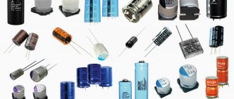
Fixed capacitors
Fixed capacitors are used in various circuits to separate the alternating and direct current components and smooth out the ripple of rectifier voltages. In combination with other circuit elements, capacitors form resonant circuits widely used in radio equipment. Fixed capacitors are classified according to their rated capacitance, accuracy class, rated operating voltage, purpose, dielectric material and design features.
The nominal values of capacitances of capacitors are established by GOST 2519 - 60. During the manufacture of capacitors, the actual value of the capacitance differs from the nominal value indicated in the marking. The permissible deviation of the capacitance from the nominal value is called tolerance. According to this principle, all capacitors are divided into five classes: 0, 1, II, III, IV, their tolerances are respectively ±2%; ±5%; ±10%; ±20% and from - 20 to + 50%.
Ceramic high voltage capacitor.
Depending on the purpose, there are loop, separating, blocking and filter capacitors. Based on the dielectric material, capacitors are divided into mica, ceramic, paper, metal-paper, paper-oil, film, glass-enamel, glass-ceramic, electrolytic, air, vacuum, gas-filled. Based on their design, capacitors are divided into tubular, disk, barrel, pot, crimped and sealed, flat and cylindrical, etc.
Regardless of the type, the capacitor is characterized by its operating voltage. The operating voltage is the voltage under which the capacitor plates can remain for a long time without breakdown of the dielectric separating them. Operating voltage is expressed in volts. Of great importance for the normal operation of the capacitor is the resistance of its insulation. With low insulation resistance, leaks occur that disrupt the normal operation of the circuit. Losses in a capacitor are characterized by the dielectric loss tangent, which expresses the ratio of the power of active losses to the reactive power of the capacitor.
In low-power capacitors, energy losses are mainly caused by dielectric conductivity and dielectric hysteresis, i.e., losses due to rotation of polar molecules in the direction of the field when voltage is applied to the plates. Losses in the plates and leads are small, so they are usually neglected. One of the most important characteristics of a capacitor is stability—the constant value of the capacitor’s capacitance during operation. The change in capacity can be either temporary or irreversible. The main factor influencing the stability of the capacitance of the capacitor is the effect of ambient temperature and heating of the capacitor due to the power dissipated on it. As the temperature rises, the geometric dimensions of the material increase, which entails a temporary (until the temperature returns to its original value) change in capacity.
Color coding
In practice, several color marking techniques are used to color code permanent capacitors.
* Tolerance 20%; a combination of two rings and a dot indicating a multiplier is possible.
** The color of the housing indicates the operating voltage.
The “+” terminal may have a larger diameter.
To mark film capacitors, 5 colored stripes or dots are used:
The first three encode the value of the nominal capacitance, the fourth - the tolerance, the fifth - the rated operating voltage.
Mechanism and structure
The composition of ceramic BaTiO3 is an aggregate made up of microcrystals ranging from 1 to 20 millimeters in diameter. This microcrystal is called a particle, and consists of a crystal structure, which is shown in Fig. 1 and 2. The particle is divided into many domains at a temperature below the Curie point. The crystal axes are aligned in the same direction within the domain, thus similar to spontaneous polarization. When heated to the Curie point and above, the crystal structure of BaTiO3 changes from tetragonal to cubic. Then, spontaneous polarization and domain walls disappear (disappear).
Structure of a ceramic capacitor.
When BaTiO3 is cooled (below the Curie point), its crystal structure rotates from cubic to quadrangular, segments up to about 1% along the C axis and along other axes are shortened. Then spontaneous polarization and domain walls appear. At the same time, the particles are distorted by influence “from outside”. At this stage, many small domain walls are generated, and the direction of spontaneous polarization in each domain can easily be completely changed, even by small (low) electric fields. Since the dielectric constant is proportional to the amount of spontaneous polarization inversion per unit volume, a large capacitance is observed.
When capacitors are stored (used) without load at temperatures below the Curie Point, the size of the randomly oriented domains becomes large and they (domains) gradually shift to a stable energy state (Fig. 3, 90 domains). This also makes it easier to collect residual stress from crystalline distortion.
In addition, the movement of space charges (ions with low mobility, free points of the crystal lattice, etc.) within the domain wall leads to polarization of the space charge. This space charge polarization adversely affects the spontaneous polarization, preventing its reversal.
In other words, the temporary transition from the generation of spontaneous polarization (spontaneous polarization is gradually rearranged to a more stable state) to inversion is complicated by the appearance of space charge polarization. In this state, a higher electric field is needed to reverse the spontaneous polarization in the domains, which in turn can be reversed by low electric field decreases and capacitance reductions. This is believed to be the mechanism of aging.
However, the microtexture of the crystal lattice returns to its original state when heated to a temperature above the Curie Point, at which point aging of the lattice begins all over again. In general, the capacitance of a multilayer ceramic capacitor with a high dielectric constant decreases approximately linearly on a logarithmic time scale - within 24 hours after heat treatment above 125 C. Please refer to the attached typical aging data of our products and the rated capacitance of capacitors. Capacitance, which has decreased as a result of natural aging, tends to be restored when the capacitors are heated to the Curie point and above.
The expected capacitance of a multilayer ceramic capacitor will be at its nominal value when these conditions are set on the equipment. We choose our capacitance amplitude based on the previous assumption. By the way, the temperature compensating values of typical capacitors do not exhibit the phenomenon of aging.
Ceramic capacitors of standard parameters.
Ceramic and glass-ceramic capacitors with a solid inorganic dielectric layer are available in high-voltage and low-voltage versions. They are compact in size and reliable. Widely in demand in computing, household, medical, military equipment, and transport. Based on their rated voltage, they are divided into high- and low-voltage.
The following ceramic capacitors are produced by design type:
- KTK – tubular;
- KDK – disk;
- SMD – surface and others.
To make ceramic capacitors, they do not use baked clay, but materials similar to it in structure - ultraporcelain, tikond, ultrasteatite. The lining is a silver layer. Ceramic and glass-ceramic devices are used in circuits in which frequency characteristics, low leakage losses, compact dimensions, and low cost are important.
Units
The easiest way is to calculate the capacitance of a flat capacitor.
If the linear dimensions of the plates-plates significantly exceed the distance between them, then the formula is valid: C= e*S/d
e is the value of the electrical permittivity of the dielectric located between the plates.
- S – area of one of the plates (in meters).
- d – distance between plates (in meters).
- C is the capacitance value in farads.
What is a farad? For a capacitor with a capacity of one farad, the voltage between the plates rises by one volt when receiving electrical energy in an amount of one coulomb. This amount of energy flows through the conductor within one second, at a current of 1 ampere. The farad received its name in honor of the famous English physicist - M. Faraday.
1 farad is a very large capacitance. In everyday practice, capacitors of much smaller capacity are used and derivatives of farads are used for designation:
- 1 Microfarad – one millionth of a farad.10-6
- 1 nanofarad is one billionth of a farad. 10-9
- 1 picofarad -10-12 farads.
| code | picofarads, pF, pF | nanofarads, nF, nF | microfarads, μF, μF |
| 109 | 1.0 pF | ||
| 159 | 1.5 pF | ||
| 229 | 2.2 pF | ||
| 339 | 3.3 pF | ||
| 479 | 4.7 pF | ||
| 689 | 6.8 pF | ||
| 100 | 10 pF | 0.01 nF | |
| 150 | 15 pF | 0.015 nF | |
| 220 | 22 pF | 0.022 nF | |
| 330 | 33 pF | 0.033 nF | |
| 470 | 47 pF | 0.047 nF | |
| 680 | 68 pF | 0.068 nF | |
| 101 | 100 pF | 0.1 nF | |
| 151 | 150 pF | 0.15 nF | |
| 221 | 220 pF | 0.22 nF | |
| 331 | 330 pF | 0.33 nF | |
| 471 | 470 pF | 0.47 nF | |
| 681 | 680 pF | 0.68 nF | |
| 102 | 1000 pF | 1 nF | |
| 152 | 1500 pF | 1.5 nF | |
| 222 | 2200 pF | 2.2 nF | |
| 332 | 3300 pF | 3.3 nF | |
| 472 | 4700 pF | 4.7 nF | |
| 682 | 6800 pF | 6.8 nF | |
| 103 | 10000 pF | 10 nF | 0.01 µF |
| 153 | 15000 pF | 15 nF | 0.015 µF |
| 223 | 22000 pF | 22 nF | 0.022 µF |
| 333 | 33000 pF | 33 nF | 0.033 µF |
| 473 | 47000 pF | 47 nF | 0.047 µF |
| 683 | 68000 pF | 68 nF | 0.068 µF |
| 104 | 100000 pF | 100 nF | 0.1 µF |
| 154 | 150000 pF | 150 nF | 0.15 µF |
| 224 | 220000 pF | 220 nF | 0.22 µF |
| 334 | 330000 pF | 330 nF | 0.33 µF |
| 474 | 470000 pF | 470 nF | 0.47 µF |
| 684 | 680000 pF | 680 nF | 0.68 µF |
| 105 | 1000000 pF | 1000 nF | 1 µF |
Four-digit marking
This marking is similar to that described above, but in this case the first three digits determine the mantissa, and the last is the exponent in base 10 to obtain the capacitance in picofarads. For example, 1622 = 162*102 pF = 16200 pF = 16.2 nF.
Capacitor markings.
Alphanumeric marking
With this marking, the letter indicates the decimal point and designation (uF, nF, pF), and the numbers indicate the capacitance value:
15p = 15 pF, 22p = 22 pF, 2n2 = 2.2 nF, 4n7 = 4.7 nF, μ33 = 0.33 µF
It is often difficult to distinguish the Russian letter “p” from the English “n”. Sometimes the letter R is used to indicate the decimal point. Usually capacitances are marked in microfarads, but if the letter R is preceded by a zero, then these are picofarads, for example: 0R5 = 0.5 pF, R47 = 0.47 µF, 6R8 = 6.8 µF .
Planar ceramic capacitors
Ceramic SMD capacitors are usually not marked at all except for color (I don’t know the color marking, if anyone can tell you, I’ll be glad, I only know that the lighter the capacitance, the smaller the capacity) or are marked with one or two letters and a number.
The first letter, if present, indicates the manufacturer, the second letter indicates the mantissa in accordance with the table below, the number is an exponent in base 10, to obtain the capacitance in picofarads.
Example:
N1 /from the table we determine the mantissa: N=3.3/ = 3.3*101pF = 33pF
S3 /according to table S=4.7/ = 4.7*103pF = 4700pF = 4.7nF
Sometimes Latin letter coding is used. To decipher, you should use the table of letter coding of the operating voltage.
Table of marking capacitors by operating voltage.
Planar electrolytic capacitors
Electrolytic SMD capacitors are marked in two ways:
1) Capacitance in microfarads and operating voltage, for example: 10 6.3V = 10 µF at 6.3V.
2) A letter and three digits, where the letter indicates the operating voltage according to the table below, the first two digits determine the mantissa, the last digit is the exponent in base 10, to obtain the capacitance in picofarads.
It will be interesting➡ What is the polarity of a capacitor and how to determine it?
The stripe on such capacitors indicates the positive terminal. Example: according to table “A” - voltage is 10V, 105 is 10*105 pF = 1 µF, i.e. this is a 1uF capacitor at 10V
Marking of capacitors with nonlinear temperature dependence
Table 4
| TKE Group* | Tolerance[%] | Temperature**[°C] | Letter code *** | Color*** |
| Y5F | ±7,5 | -30…+85 | ||
| Y5P | ±10 | -30…+85 | silver | |
| Y5R | -30…+85 | R | grey | |
| Y5S | ±22 | -30…+85 | S | brown |
| Y5U | +22…-56 | -30…+85 | A | |
| Y5V(2F) | +22…-82 | -30…+85 | ||
| X5F | ±7,5 | -55…+85 | ||
| X5P | ±10 | -55…+85 | ||
| X5S | ±22 | -55…+85 | ||
| X5U | +22…-56 | -55…+85 | blue | |
| X5V | +22…-82 | -55..+86 | ||
| X7R(2R) | ±15 | -55…+125 | ||
| Z5F | ±7,5 | -10…+85 | IN | |
| Z5P | ±10 | -10…+85 | WITH | |
| Z5S | ±22 | -10…+85 | ||
| Z5U(2E) | +22…-56 | -10…+85 | E | |
| Z5V | +22…-82 | -10…+85 | F | green |
| SL0(GP) | +150…-1500 | -55…+150 | Nil | white |
* Designation according to EIA standard, IEC in parentheses.
**Depending on the technologies that the company has, the range may be different. For example: for group Y5P normalizes -55…+125 °С.
***According to EIA. Some use a different encoding.
Rice. 1
Table 5
| Marks stripes, rings, dots | 1 | 2 | 3 | 4 | 5 | 6 |
| 3 marks* | 1st digit | 2nd digit | Factor | — | — | — |
| 4 tags | 1st digit | 2nd digit | Factor | Tolerance | — | — |
| 4 tags | 1st digit | 2nd digit | Factor | Voltage | — | — |
| 4 tags | 1st and 2nd digits | Factor | Tolerance | Voltage | — | — |
| 5 marks | 1st digit | 2nd digit | Factor | Tolerance | Voltage | — |
| 5 marks" | 1st digit | 2nd digit | Factor | Tolerance | TKE | — |
| 6 marks | 1st digit | 2nd digit | 3rd digit | Factor | Tolerance | TKE |
* Tolerance 20%; a combination of two rings and a dot indicating a multiplier is possible.
** The color of the housing indicates the operating voltage.
Rice. 2
Table 6
| Color | 1st digit µF | 2nd digit uF | Multiplier | Voltage |
| Black | 0 | 1 | 10 | |
| Brown | 1 | 1 | 10 | |
| Red | 2 | 2 | 100 | |
| Orange | 3 | 3 | ||
| Yellow | 4 | 4 | 6,3 | |
| Green | 5 | 5 | 16 | |
| Blue | 6 | 6 | 20 | |
| Violet | 7 | 7 | ||
| Grey | 8 | 8 | 0,01 | 25 |
| White | 9 | 9 | 0,1 | 3 |
| Pink | 35 | |||
Rice. 3
Table 7
| Color | 1st digit pF | 2nd digit pF | 3rd digit pF | Factor | Tolerance | TKE |
| Silver | 0,01 | 10% | Y5P | |||
| Gold | 0,1 | 5% | ||||
| Black | 0 | 0 | 1 | 20%* | NPO | |
| Brown | 1 | 1 | 1 | 10 | 1%** | Y56/N33 |
| Red | 2 | 2 | 2 | 100 | 2% | N75 |
| Orange | 3 | 3 | 3 | 103 | N150 | |
| Yellow | 4 | 4 | 4 | 104 | N220 | |
| Green | 5 | 5 | 5 | 105 | N330 | |
| Blue | 6 | 6 | 6 | 106 | N470 | |
| Violet | 7 | 7 | 7 | 107 | N750 | |
| Grey | 8 | 8 | 8 | 108 | 30% | Y5R |
| White | 9 | 9 | 9 | +80/-20% | SL | |
* For capacitances less than 10 pF, the tolerance is ±2.0 pF. ** For capacitances less than 10 pF, tolerance ±0.1 pF.
Rice. 4
Table 8
| Color | 1st and 2nd digit pF | Factor | Tolerance | Voltage |
| Black | 10 | 1 | 20% | 4 |
| Brown | 12 | 10 | 1% | 6,3 |
| Red | 15 | 100 | 2% | 10 |
| Orange | 18 | 103 | 0.25 pF | 16 |
| Yellow | 22 | 104 | 0.5 pF | 40 |
| Green | 27 | 105 | 5% | 20/25 |
| Blue | 33 | 106 | 1% | 30/32 |
| Violet | 39 | 107 | -2О…+5О% | |
| Grey | 47 | 0,01 | -20…+80% | 3,2 |
| White | 56 | 0,1 | 10% | 63 |
| Silver | 68 | 2,5 | ||
| Gold | 82 | 5% | 1,6 | |
To mark film capacitors, 5 colored stripes or dots are used. The first three encode the value of the nominal capacitance, the fourth - the tolerance, the fifth - the rated operating voltage.
Rice. 5
Table 9
| Nominal capacitance [µF] | Tolerance | Voltage | |||
| 0,01 | ±10% | 250 | |||
| 0,015 | |||||
| 0,02 | |||||
| 0,03 | |||||
| 0,04 | |||||
| 0,06 | |||||
| 0,10 | |||||
| 0,15 | |||||
| 0,22 | |||||
| 0,33 | ±20 | 400 | |||
| 0,47 | |||||
| 0,68 | |||||
| 1,0 | |||||
| 1,5 | |||||
| 2,2 | |||||
| 3,3 | |||||
| 4,7 | |||||
| 6,8 | |||||
| 1 strip | 2 lane | 3 lane | 4 lane | 5 lane | |
Some notes and tips on working with capacitors
It must be remembered that capacitors with a higher rated voltage should be selected as the ambient temperature increases, creating a larger voltage reserve to ensure high reliability. If the maximum constant operating voltage of the capacitor is specified, this refers to the maximum temperature (unless otherwise stated). Therefore, capacitors always operate with a certain margin of safety. And yet, it is desirable to ensure that their actual operating voltage is at a level of 0.5-0.6 nominal.
If a limit value for alternating voltage is specified for a capacitor, then this applies to a frequency of (50-60) Hz. For higher frequencies or in the case of pulsed signals, the operating voltages should be further reduced to avoid overheating of the devices due to dielectric losses. High-capacity capacitors with low leakage currents are able to retain the accumulated charge for a long time after the equipment is turned off. To ensure faster discharge, for greater safety, you should connect a resistor with a resistance of 1 MOhm (0.5 W) in parallel with the capacitor.
Marking capacitors using a numerical-alphabetic code.
The marking of capacitors may indicate the following parameters: Type of capacitor, its rated capacity, permissible deviation of capacitance, Temperature Coefficient of Capacitance (TKE), rated operating voltage.
The order of marking may be different - the first line may be the rated voltage, TKE or the manufacturer's brand name. TKE may be absent altogether, the rated voltage is also not always indicated! There is almost always a marking of the nominal capacity. As for capacity, there are various ways to encode it symbolically. 1. Marking of the container using three numbers. With this marking, the first two digits indicate the capacitance value in picofarads, and the last one indicates the bit depth, i.e., the number of zeros that must be added to the first two digits. But if the last digit is “9”, division by 10 occurs.
| Code | Capacitance(pF) | Capacitance(nF) | Capacitance(uF) |
| 109 | 1.0(pF) | 0.001(nF) | 0.000001(uF) |
| 159 | 1.5(pF) | 0.0015(nF) | 0.0000015(uF) |
| 229 | 2.2(pF) | 0.0022(nF) | 0.0000022(uF) |
| 339 | 3.3(pF) | 0.0033(nF) | 0.0000033(uF) |
| 479 | 4.7(pF) | 0.0047(nF) | 0.0000047(uF) |
| 689 | 6.8(pF) | 0.0068(nF) | 0.0000068(uF) |
| 100 | 10(pF) | 0.01(nF) | 0.00001(uF) |
| 150 | 15(pF) | 0.015(nF) | 0.000015(uF) |
| 220 | 22(pF) | 0.022(nF) | 0.000022(uF) |
| 330 | 33(pF) | 0.033(nF) | 0.000033(uF) |
| 470 | 47(pF) | 0.047(nF) | 0.000047(uF) |
| 680 | 68(pF) | 0.068(nF) | 0.000068(uF) |
| 101 | 100(pF) | 0.1(nF) | 0.0001(uF) |
| 151 | 150(pF) | 0.15(nF) | 0.00015(uF) |
| 221 | 220(pF) | 0.22(nF) | 0.00022(uF) |
| 331 | 330(pF) | 0.33(nF) | 0.00033(uF) |
| 471 | 470(pF) | 0.47(nF) | 0.00047(uF) |
| 681 | 680(pF) | 0.68(nF) | 0.00068(uF) |
| 102 | 1000(pF) | 1(nF) | 0.001(uF) |
| 152 | 1500(pF) | 1.5(nF) | 0.0015(uF) |
| 222 | 2200(pF) | 2.2(nF) | 0.0022(uF) |
| 332 | 3300(pF) | 3.3(nF) | 0.0033(uF) |
| 472 | 4700(pF) | 4.7(nF) | 0.0047(uF) |
| 682 | 6800(pF) | 6.8(nF) | 0.0068(uF) |
| 103 | 10000(pF) | 10(nF) | 0.01(uF) |
| 153 | 15000(pF) | 15(nF) | 0.015(uF) |
| 223 | 22000(pF) | 22(nF) | 0.022(uF) |
| 333 | 33000(pF) | 33(nF) | 0.033(uF) |
| 473 | 47000(pF) | 47(nF) | 0.047(uF) |
| 683 | 68000(pF) | 68(nF) | 0.068(uF) |
| 104 | 100000(pF) | 100(nF) | 0.1(uF) |
| 154 | 150000(pF) | 150(nF) | 0.15(uF) |
| 224 | 220000(pF) | 220(nF) | 0.22(uF) |
| 334 | 330000(pF) | 330(nF) | 0.33(uF) |
| 474 | 470000(pF) | 470(nF) | 0.47(uF) |
| 684 | 680000(pF) | 680(nF) | 0.68(uF) |
| 105 | 1000000(pF) | 1000(nF) | 1.0(uF) |
2. The second option - marking is done not in pico, but in microfarads, and the letter µ is placed instead of the decimal point.
| Code | Capacitance(uF) |
| µ1 | 0,1 |
| µ47 | 0,47 |
| 1 | 1,0 |
| 4µ7 | 4,7 |
| 10µ | 10,0 |
| 100µ | 100,0 |
3. Third option.
| Code | Capacitance(uF) |
| p10 | 0.1pF |
| IP5 | 0.47pF |
| 332p | 332pF |
| 1HO or 1no | 1nF |
| 15H or 15no | 15.0nF |
| 33H2 or 33n2 | 33.2nF |
| 590H or 590n | 590nF |
| m15 | 0.15uF |
| 1m5 | 1.5uF |
| 33m2 | 33.2uF |
| 330m | 330uF |
| 10m | 10.0uF |
Soviet capacitors used “p” instead of the Latin “r”.
The permissible deviation of the nominal capacity is marked with a letter, often the letter follows the code defining the capacity (the same line).
| Letter designation | Tolerance(%) |
| B | ± 0,1 |
| C | ± 0,25 |
| D | ± 0,5 |
| F | ± 1 |
| G | ± 2 |
| J | ± 5 |
| K | ± 10 |
| M | ± 20 |
| N | ± 30 |
| Q | -10…+30 |
| T | -10…+50 |
| Y | -10…+100 |
| S | -20…+50 |
| Z | -20…+80 |
Further, there may be (or may not be!) marking of the Temperature Coefficient of Capacity (TKE). For capacitors with non-standardized TKE, coding is done using letters.
| Tolerance at -60²…+85²(%) designation | Letter code |
| ± 10 | B |
| ± 20 | Z |
| ± 30 | D |
| ± 50 | X |
| ± 70 | E |
| ± 90 | F |
Capacitors with a linear dependence on temperature.
| TKE(ppm/²C) | Letter code |
| 100(+130….-49) | A |
| 33 | N |
| 0(+30….-47) | C |
| -33(+30….-80) | H |
| -75(+30….-80) | L |
| -150(+30….-105) | P |
| -220(+30….-120) | R |
| -330(+60….-180) | S |
| -470(+60….-210) | T |
| -750(+120….-330) | U |
| -500(-250….-670) | V |
| -2200 | K |
Next comes the voltage in volts, most often in the form of a regular number. For example, the capacitor in this picture is marked with two lines. The first (104J) means that its capacitance is 0.1 μF (104), the permissible deviation of the capacitance does not exceed ± 5% (J). The second (100V) is the voltage in volts.
In addition, the voltage of the capacitors can also be encoded using letters (see table below).
| Voltage (V) | Letter code |
| 1 | I |
| 1,6 | R |
| 3,2 | A |
| 4 | C |
| 6,3 | B |
| 10 | D |
| 16 | E |
| 20 | F |
| 25 | G |
| 32 | H |
| 40 | C |
| 50 | J |
| 63 | K |
| 80 | L |
| 100 | N |
| 125 | P |
| 160 | Q |
| 200 | Z |
| 250 | W |
| 315 | X |
| 400 | Y |
| 450 | U |
| 500 | V |
Temperature coefficient of capacitance (TKE) Marking of capacitors with non-standardized TKE
table 2
| TKE Group | Tolerance at -6О…+85°С[%] | Letter code | Color* |
| H10 | ±10 | IN | orange+black |
| H20 | ±20 | Z | orange+red |
| H30 | ±30 | D | orange+green |
| H50 | ±50 | X | orange+blue |
| H70 | ±70 | E | orange+purple |
| H90 | ±90 | F | orange+white |
* Modern color coding, Colored stripes or dots. The second color can be represented by the color of the body.
Storage Features
Tantalum capacitors are able to maintain performance characteristics for a long time. If the required conditions are observed (temperature up to +40°, relative humidity 60%), the capacitor loses its ability to be soldered during long-term storage, while maintaining other performance characteristics.
General recommendations for extending the service life of a tantalum capacitor and increasing the safety of its operation:
- Compliance with technical process requirements;
- Multi-stage product quality control;
- Compliance with storage conditions;
- Fulfilling the requirements for organizing a workplace for mounting devices on a board;
- Compliance with the recommended soldering temperature conditions;
- Correct selection of safe operating modes;
- Compliance with operating requirements.
Features of the use of capacitor 2A 104 J
Capacitor
Good consumer parameters make it possible to use radio components of this category to solve various engineering problems. Capacitors are used in low-voltage circuits to create high-quality noise suppression filters. When preparing design calculations, the following advantageous features can be taken into account:
- minimal parasitic inductance;
- significant discharge current;
- reliability;
- long-term preservation of original operating parameters under difficult operating conditions.
When considering analogues, attention should be paid to the relatively high temperature dependence. Ceramic capacitors do not have a large enough capacity for their comparative dimensions.