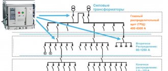
At all stages of production, transmission, distribution and consumption of electrical energy in almost all sectors of the national economy, electrical devices play an important role.
Electrical devices (contactors, starters, relays, electromagnets) are part of automatic, semi-automatic and manual control systems for electrical power plants, electric drives, electric lighting devices, electrical technological installations, etc. They are used to control start-up, regulate rotation speed and implement electric braking electric motors. Electrical devices are used to regulate the currents and voltages of generators. They carry out the functions of monitoring and protecting installations that consume electricity.
Thus, the use of electromechanical devices allows you to control the operation of electrical and non-electrical objects according to a given program, as well as protect these objects from undesirable conditions - overloads, overvoltages, unacceptably high currents, etc.
Many electrical devices are designed to perform a single function in a control or protection system, but there are also multifunctional devices. The operation of electromechanical devices in automation systems is based on a number of physical phenomena: the interaction of ferromagnetic bodies in a magnetic field, the force interaction of a conductor with current and a magnetic field, the occurrence of EMF in coils and eddy currents in massive bodies of electrically conductive material when an alternating magnetic field appears, the thermal effect of electric current, etc.
The main parts of electrical apparatus are
- electrical contacts (fixed and moving, main and auxiliary),
- mechanical or electromagnetic drive of the contact group (bringing into contact and pressing moving and fixed contacts),
- control handles (buttons) and working windings. The electrical device is triggered, that is, it closes and opens contacts or connects the moving and stationary parts of the electromagnetic mechanism, under the influence of:
1) service personnel pressing control handles (buttons); in this case, the device is called manual or semi-automatic; 2) electrical quantities characterizing the operation of the controlled (managed) object, changing the current or voltage on the working windings; in this case the device is called automatic.
Depending on the functions that the device must provide, various requirements may be placed on it, but the main requirements are reliability and accuracy of operation: reliable connection of contacts, low electrical resistance at the junction of the contacts, accuracy of the dependence of the moment of operation on the value of the control current or voltage.
Electric cars
Definition 1
Electrical equipment is a set of electrical devices and products that are used for the production, distribution, transmission, consumption and conversion of electrical energy.
Electrical equipment includes electrical apparatus and electrical machines. Electrical machines are electromechanical energy converters. These include electrical generators, motors, and transformers. Electric motors convert electrical energy into mechanical work and heat. An electric generator converts non-electrical energy into electrical energy and heat. Electrical machines are classified according to:
- Kind of current. According to this criterion, electrical machines are divided into three-phase and single-phase machines, as well as alternating and direct current machines.
- The relationship between the speed of rotation of the magnetic field and the rotor. According to this criterion, electric machines are divided into asynchronous and synchronous.
- Purpose. According to this criterion, electric machines are divided into generators, electric motors, converters, etc.
- Constructive execution. According to this criterion, electrical machines are divided into several subtypes: according to the method of cooling (natural, air, forced or hydrogen), according to the method of environmental protection (open, explosion-proof, closed, protected, etc.), according to the method of fastening (on flanges, paws, bearing struts).
Are you an expert in this subject area? We invite you to become the author of the Directory Working Conditions
The following electrical devices are distinguished by purpose:
1) switching (disconnectors, switches, switches); 2) protective, the main purpose of which is to protect electrical circuits from unacceptably high currents, overvoltages, voltage drops, etc. (fuses, protection relays); 3) ballasts, designed to control electric drives and other industrial consumers of electricity (contactors, starters, control relays); 4) monitoring and regulating, designed to monitor and maintain the main process parameters (sensors and relays) in a given range; 5) electromagnets (power), used to hold or move objects in the production or management process.
This chapter discusses electrical devices (relays, starters, contactors and electromagnets) and some control and regulation circuits that use electromechanical devices.
First of all, let's consider the features of the operation of electrical contacts and the operation of the electromagnetic mechanism - the drive of the contact group of electrical devices.
Control and protection devices
Automatic remote control devices include electromagnetic starters, contactors and relays of various kinds, the switching of which is carried out when an electrical signal (voltage or current) is applied to their coils and this signal is removed. They are two-position switching devices with self-resetting, which are turned on and off by an electrical signal.
12.1. Automatic control devices. Purpose, device, choice
Electromagnetic starters. Designed for remote control of electrical installations (for electric motors, starting, stopping, braking, reversing), as well as with a thermal relay for protection against small but long-term overloads. The starter also protects the electrical installation from voltage reduction or disappearance and from self-starting of the engine after voltage restoration, the so-called zero protection. In accordance with the listed functions, the starter may include a contactor, control buttons, thermal protection relays, and signal lamps located in one housing.
Electromagnetic starters differ from each other according to: purpose (irreversible, reversible); degree of protection from environmental influences; the presence of thermal relays (without thermal relays, with thermal relays); type of blocking in reversing starters (mechanical, electrical, mechanical and electrical at the same time); the presence of control buttons built into the starter shell (without buttons, with buttons); size, size or transmitted power; voltage of the main circuit and control circuit.
The main power (linear) contacts of the starter are included in the cutting of wires supplying the electrical installation (electric motor). The heating elements of thermal relays are also included in the wires of two or three phases. The electromagnet coil is connected to the network through the breaking contacts of thermal relays and control buttons (Fig. 12.1).
Fig. 12.1. Electric motor control circuit using an electromagnetic starter
Starters of the PME and PA series are used, as well as the currently produced series PM12, PML, PMS, PMA. Starters of the PM12, PME, PML, PMS, PMA series have a linear W-shaped or U-shaped electromagnetic system, the PA and PAE series have a rotary-lever design (Fig. 12.2).
Rice. 12.2. Design of magnetic starters with linear W-shaped (a) and rotary-lever U-shaped (b) magnetic circuits: 1 – base; 2 – spring; 3 – fixed contact; 4 – moving contact; 5 – traverse, 6 – coil; 7 – core; 8 – anchor; 9 – short-circuited turn; 10 – block contact bridge
The magnetic starter system is assembled from separate sheets of electrical steel. The starter coil is powered by alternating current, so a pulsating magnetic flux appears in the magnetic circuit. To eliminate vibration, armature wear and burning of the main contacts, the end of the core in the area where the armature is adjacent to it is broken and part of it is covered with a short-circuited damper coil made of copper or brass. In a short-circuited coil, an alternating magnetic flux induces an emf, and the current flowing through it creates its own magnetic flux, shifted in phase with respect to the main one. Thus, two magnetic fluxes appear in the air gap, shifted in phase with each other. Their sum at any moment is not equal to zero, therefore, the force of attraction of the electromagnet does not decrease to zero.
Starters are produced in sizes 0...7 for power 1...100 kW and currents 4...200A. The frequency of starts per hour according to mechanical wear resistance at rated current for starters of the 5th value is 3600, 6th and 7th values - 2400. Mechanical wear resistance for starters of the 5th value is 16 million cycles, 6th and 7th magnitude - 5 million cycles. The switching (electrical) wear resistance of the starters is 3 million cycles.
An electromagnetic starter is mainly selected by size or size, design, presence of reverse and thermal relay, voltage and other characteristics according to the alphabetic and digital decoding of the starter type. The structure of the symbols for starters of the most common series is given below.
1 – Series designation.
2 – Symbol of the rated current value: 010 - 10A, 025 - 25A, 040 - 40A, 063 - 63A, 100 - 100A, 125 - 125A, 160 - 160A, 250 - 250A.
3 – Designation of the starter version according to purpose and presence of a thermal relay: 1- without thermal relay, irreversible; 2 - with thermal relay, irreversible; 5 - without thermal relay, reversible, with electrical and mechanical interlocking; 6-with traction relay, reversible, with electrical and mechanical locking.
4 – Designation of the starter version according to the degree of protection and the presence of buttons: O - IP00; 1-IP54 without buttons; 2-IP54 with “Start” and “Stop” buttons; 4-IP40 without buttons; 5-IP20; 6-IP40 with "Start" and "Stop" buttons.
5 – Designation of the starter version according to the type of control circuit current: O - alternating current. Rated voltage of the retractor coil, V: 24,36,40,48,110,127,220,230,240,380,400,415,440,500,660V frequency 50 Hz.
6 – Purpose of climatic version according to GOST 15150 - 69: U - standard version, T - tropical version.
7 – Designation of the placement category according to GOST 15150 - 69.
8 – Designation of starter design for wear resistance: A, B, C.
9 – Designation of specifications according to which the starter is produced: TU 16-89 and GFR. 644236.033 TU.
Types of thermal relays used for starters: RTTS-10, RTT-121, RTT-131, RTT-231, RTT310, RT362.
1 – Series designation.
2 – Designation of size (size) by transmitted power: 0-1kW, 1-4kW, 2-10kW.
3 – Designation of design for protection from environmental influences: 1-open, 2-protected, 3-dust-splash-proof, 4-dust-moisture-proof.
4 – Designation of the version of starters according to purpose, presence of reverse and thermal relay: 1-irreversible without relay, 2-irreversible with relay, 3-reversible without relay, 4-reversible with relay.
Rated voltage of the retractor coil is 24, 36, 40, 48, 110, 127, 220, 230, 240, 380, 400, 415, 440, 500, 660V frequency 50 Hz.
Starters are manufactured according to climatic design and placement category: UHL4, U3, T3, O4, and wear resistance design: A, B, V.
Types of thermal relays used for starters: RTT5-10, RTT-141.
Contactor. It is a two-position device with self-resetting, designed for frequent switching of operating currents, as well as for rare shutdowns due to overload currents. Switching on of contactors is remote using built-in electromagnets.
Contactors differ from each other by: the type of current in the main circuit and control circuit (DC, AC); number of main poles (from one to five), rated current of the main circuits (4; 6.5; 10, 16, 25, 40, 63, 100, 160, 250, 400, 630, 1000, 2500 A); rated voltage of the main circuit (DC - 110,220,400,600V; AC - 220,380,500,660,1140V); rated voltage of the switching coil (DC - 24,48,60,110,220V; AC - 24,36,110,127, 220,230,240,380,400,415,440,500,660V); arc extinguishing method (with magnetic extinguishing or arc extinguishing grid); the presence and execution of block contacts; type of connection of conductors; class corresponding to the switching frequency; accommodation categories; exposure to climatic factors; degree of protection.
Mechanical wear resistance allows for from 250 thousand to 10 million cycles, the response time of contactors ranges from tenths to hundredths of a second.
Contactors have an electromagnet design with a valve (hinged) type armature (Fig. 12.3), and a forward armature, similar to the design of the starter electromagnet (Fig. 12.2).
Rice. 12.3. Direct current contactor design: 1 – fixed main contact; 2 – spark arresting grid; 3 – insulating partitions; 4 – arc extinguishing chamber; 5 – movable main contact; 6, 9 – spring; 7 – flexible conductor; 8 – anchor; 10 – closing block contacts; 11 – opening block contacts; 12 – electromagnet coil; 13 – contacts for supplying voltage to the coil; 14 – fixed core.
The fixed part has a retractor coil 12, a fixed contact 1, a core 14. The moving part consists of a moving contact 5, an armature 8 and a bridge of block contacts 10, 11. AC contactors, according to the principle of their operation and the main design element, do not differ from DC contactors . The difference is that the AC contactor has a laminated magnetic system made up of individual insulated steel plates and a short-circuited coil at the end of the core, similar to that for starters.
The following types of DC contactors are produced: KPV 600, KPV 620, KP, KPD, KPM, KN, KMI: alternating current KT 600, CNM, KT 7000, KTP 600, KTP 64, KTP 65, KTV, KTD, KTI, KTU.
The letter designations of the types of contactors of direct and alternating current are deciphered as follows: K - contactor, P - direct current, T - alternating current, V - vertical installation, D - industrial use, M - marine version or modification, N - increased reliability, U - coal industry. When the letter P appears after the letter T, this means that the AC contactor is powered by DC control circuits. The digital designation of contactors is not systematized (each series has its own type designation) and therefore you should always refer to the contactor passport for its technical data. When choosing contactors, it is necessary to proceed from the conditions of their use and the characteristics of the electric drive. The following basic requirements: ensuring the necessary switching capacity, heating and switching wear resistance.
Electromagnetic relay. A relay is a switching device designed to produce abrupt changes in controlled circuits at a given value of electrical influencing quantities. An electromagnetic relay is a device for switching low-current control circuits of an electric drive in accordance with the electrical signal supplied to its coil. The scope of application of the relay is very wide. They are used as current and voltage sensors, intermediate elements for transmitting commands from one circuit to another and multiplying signals from an electrical signal amplifier, time sensors, output elements of various electric drive coordinate sensors and technological parameters of working machines and mechanisms.
The electromagnetic relay works as follows (Fig. 12.4). On the core 2 of the magnetic system there is a coil 1, to which the input electrical signal is supplied.
Rice. 12.4. Electromagnetic relay
When the current (voltage) exceeds a certain value, called the current (voltage) of the relay operation, the electromagnetic force created by it will become greater than the opposing force of the return spring 10. The armature 3 will be attracted to the core 2 and the traverse 6, rising, will ensure the closure of contacts 8 and the opening of contacts 7. The pressing force in the contacts is created by spring 9.
If you reduce (turn off) the current (voltage) in the coil, then armature 3, under the action of spring 10, will move to its original position and the relay contacts will return to their normal (original) position. The current (voltage) at which the armature returns to its original position is called the return or release current (voltage). The ratio of the return current (voltage) to the operating current (voltage) is called the relay return ratio.
Since relay contacts switch small currents from milliamps to 10A, they usually do not use arc chutes, and the contact designs are simple.
The main types of relays used in electric drive control circuits: time electromechanical - 2РВМ, CRONO, BC-33, ВС-43, РВ-100, РВ-200; time electromagnetic – REV-811…REV-818, REV-881…REV884; three-phase voltage control – EL-11...EL-13; intermediate - RPLU, REU-11, REU-21, NN63R, NN64R, PE-37, RP-8, RP-9, RP-11, RP-12, RP-16...RP-18, RP-23, RP- 25, RP-251...RP-256, RP-21004, R153, R3, R4, R15, REP-15, REP-25, REP-34, RPU-2M, RPU-3M, RPL, REV-822, REV- 826; current - RT-01, RT-40, RT-140, RTD-11, RTD-12, RST-11, RST-13, RE-830; voltage – RN-01, RN-51, RN-151, RN-53, RN-153, RN-54, RN-154.
Reed electromagnetic relays . They have the peculiarity that their contacts are sealed, which increases their wear resistance and operational reliability. The reed switch is a ferromagnetic (iron-nickel alloy) contact parts (moving and stationary contacts) hermetically sealed in a glass container filled with neutral gas. The reed switch is activated by the external magnetic field of a coil (Fig. 12.5) or a permanent magnet.
Rice. 12.5. Reed relay
If DC voltage is applied to coil 4, then a current will begin to flow in it, creating a magnetic flux in the magnetic wire 5 and contacts 1 and 2. Under its influence, moving contact 2 will move and close with fixed contact 1. The contacts are enclosed in a glass case 4. The wear resistance of relays with reed switches, capable of switching currents up to 5A at voltages up to 100V, reaches several tens of millions of operations with an operation time of 0.3...2.0 ms.
The following types of reed relays are produced: RGK 49, RGK 50, RGK 51, RGK 52, RGK 53, RGK 54 for a range of operating voltages 3.5,12,15,24V with a switching current of up to 3A.
12.2. Electrical installation protection devices. Purpose, device, choice
Protection devices used in electric drives include air circuit breakers, fuses and thermal relays.
Automatic air circuit breakers . Automatic circuit breakers are designed for infrequent closing and opening of an electrical circuit under load and long-term passage of current through it, as well as disconnecting the circuit during abnormal and emergency conditions: short circuits, prolonged small overloads, excessive reduction in supply voltage or its disappearance.
The contact system and mechanisms of the circuit breaker are mounted on a plastic panel. It is equipped with moving and fixed contacts and an arc extinguishing device. To influence the latch of the tripping mechanism, one or more releases are used, disconnecting their main contacts. Releases are electromagnetic or thermobital mechanisms that are triggered and cause the circuit breaker to trip instantly or with a certain time delay. The most common ones are: electromagnetic overcurrent releases, triggered when a current exceeds the installation current (short circuit, excessive overload current); electromagnetic undervoltage releases, triggered when the voltage on the coil becomes less than a preset one or disappears completely; thermal releases, triggered by small but long-term overload currents; independent releases, triggered without a time delay when voltage is applied to their coil; electromagnetic undercurrent and reverse current releases, activated when the current respectively becomes less than a certain value or changes its direction.
Let's consider the principle of operation of some releases (Fig. 12.6. a, b, c).
Fig. 12.6. Schemes of operation of electromagnetic releases: a – maximum current; b – minimum voltage; c – thermal release: 1 – spring; 2 – latch; 3 – coil; 4 – steel core; 5 – contacts; 6 – bimetallic plate; 7 – heating element
In a circuit breaker with an electromagnetic overcurrent release, when the current reaches a set limit value or a short circuit, coil 3 retracts the steel core 4 and releases the latch 2, which, under the action of spring 1, breaks the power contacts 5. In a circuit breaker with an electromagnetic undervoltage release or current, coil 3 holds core 4 and the latch associated with it until the mains voltage, and therefore the current in the coil, drops to the established limit value or disappears completely, after which core 4 is released and latch 2 releases spring 1, the power circuit Contacts 5 are then broken. Electromagnetic releases operate almost instantly - their own response time is 0.02...0.03 s. In a circuit breaker with a thermal release, the current passing through the heating element 7 heats the bimetallic plate 6, which removes the latch 2 of the spring 1 and thereby disconnects the power contacts 5. From a cold state at an ambient temperature of 40 ° C and a load of 1.1 rated thermal the release does not operate for an hour, at a load of 1.35 rated it operates in 30 minutes, and at a sixfold load - in no more than 2...10 s.
An automatic circuit breaker with three releases simultaneously (electromagnetic maximum value, electromagnetic minimum value and thermal) replaces the switch, electromagnetic starter, fuse link and thermal relay.
The schematic diagram of a universal circuit breaker for high currents is shown in Fig. 12.7.
The current-carrying circuit has main 3 and arc-extinguishing contacts 1, which are held or returned to their original position by spring 13. Turning the circuit breaker on and off manually with handle 8 or electromagnets 7 and 11. Links 10,12 and stop 9 are a free-acting mechanism, the position of the levers of which when automatically switched off, shown as a dashed line. In case of short circuit currents, the circuit breaker is switched off by current element 5, in case of low voltage - by element 6, in case of overload currents - by heating bimetallic element 4. To extinguish the arc that occurs during switching, arc extinguishing chamber 2 is used.
Rice. 12.7. Schematic diagram of a circuit breaker for high currents
According to their design, there are automatic circuit breakers with a plastic case and a cover for currents up to 630A - installation ones and without a case and cover for currents from 630 to 15000A - universal. Based on the shutdown time, automatic circuit breakers are distinguished between low-speed and high-speed.
Considering only automatic installation machines, the following most used series should be noted: AP-50 2(3) MTN; AE2000; VA51-35; A3700...A3716 up to 180A; A3726 up to 250A; VA5700...VA5731 up to 16...100A; VA5735 up to 100A; VA57F35 up to 100A; VM-40IP (16.25A); VM-403P (16,25,40A); "SHIELD", DEK-1P (10...63A); DEK-2P (10-63A); AB-50-45; VA 50-41…VA 56-41; AB 2M; "Electron" 306С, 316В, 325С, 325В, 340В, 340С, VAMU, Legrand DRH and others.
Automatic switches intended for installation in apartments and meeting all the requirements for installation products are called household: series AE-1000, VA-101, VA1-103, VA-201, VA-301...BA304; VA 92-29; VA47; BA88; "Shield"; Legrand DRKHTM, LRTM and others.
The rated currents of circuit breakers and release settings should be selected based on the rated current of the circuit and the possible overload current. The switching capacity is checked by the permissible short circuit current. Between the rated current of the thermal release Iset.heat and the operating current of the circuit there must be a condition Iset.heat = 1.25 Ioper. The electromagnetic release current Iset.em for powering single electric motors should be Iset.em=1.25 Istart (Istart is the starting current of the electric motor). For a group of electric motors, the starting current of the larger electric motor Istart.max and the total current of the others are taken into account, that is
where n is the number of electric motors.
Thermal relays. Thermal relays are used to protect electric motors from small but long-term overloads that arise due to the passage of increased currents through the windings, overloads of the working mechanism for technological reasons, difficult starting conditions, a prolonged decrease in network voltage, or a break in one of the phases. Thermal overloads cause accelerated aging and destruction of insulation, which leads to short circuits. The main requirement for thermal protection is that it must operate when the electric motor is overloaded over 20% within no more than 20 minutes from the moment the established temperature is reached. The principle of operation of a thermal relay is similar to the principle of operation of a thermal release of a circuit breaker. It is only necessary to note the features of the thermal relay. A thermobimetallic plate, capable of bending when heated, consists of two dissimilar metals firmly connected to each other, having different coefficients of thermal expansion. According to the method of heating the bimetallic plate, thermal relays with direct, indirect and combined heating are distinguished.
Thermal relays of the TRN, TRP, RTT and RTL types are widely used. Thermal relays of the TRN type are bipolar with temperature compensation, manual reset and replaceable heaters, designed for currents from 0.32 to 40A. TRP thermal relays are single-pole, manual reset or self-reset, without temperature compensation and with replaceable heaters for currents from 25 to 150A. Three-pole relays of the PTT and RTL types provide accelerated response in case of phase loss and have a mechanism for accelerated response, temperature compensation, and control limits for the set current - 0.75...1.25 of the nominal one. Thermal relays of the PTT type are available in five versions according to rated current: O - 0.2...10A; 1-0.2…25A; 2-10...63A; 3-63...160A; 4-125…630A. Thermal relays of the RTL series come in three versions according to rated current: RTL-1000-up to 25A, RTL-2000-up to 80A and RTL-3000-up to 200A.
12.3. Modern control and protection devices