Device
A semiconductor diode is a two-terminal device made from a semiconductor substance that allows current to pass in one direction and virtually no current in the other.
The main element of the diode is a crystalline component with a pn junction, to which a metal anode and a cathode are soldered (welded). The passage of direct current is carried out when a positive potential, relative to the cathode, is applied to the anode.
Note! Holes move in the direction of forward current. The electrons move in the opposite direction.
The diode design can be point, planar, or polycrystalline.
Additional Information. There are no fundamental differences between point and planar bipolar devices.
The structure of a point diode is shown in figure (a).
When a thin needle, with an impurity deposited on it, is welded to a semiconductor plate with a certain type of electrical conductivity, a hemispherical mini pn junction with a different type of conductivity is formed. This action is called diode forming.
The production of a planar two-terminal network is carried out by the diffusion fusion method. Figure (b) shows an alloy germanium diode and the principle of its design. In a plate of n-type germanium, when a drop of indium is fused there at 500 degrees, a layer of p-type germanium is formed. The lead contacts soldered to the germanium and indium base plate are made of nickel.
Germanium, silicon, gallium arsenide and carbide are used in the production of semiconductor wafers. Semiconductor monocrystalline wafers with a correct structure throughout the entire volume are used as the basis for point and planar two-terminal networks.
In polycrystalline two-terminal networks, the pn junction is formed by semiconductor layers, which include a large number of randomly oriented small crystals that do not represent a single single-crystalline form. These are selenium, titanium and copper oxide bipolars.
Main characteristics and parameters of diodes
For the device to work correctly, it must be selected in accordance with:
- Current-voltage characteristic;
- Maximum permissible constant reverse voltage;
- Maximum permissible pulse reverse voltage;
- Maximum permissible direct direct current;
- Maximum permissible pulsed direct current;
- Rated direct direct current;
- Direct direct voltage at rated current;
- Constant reverse current, indicated at the maximum permissible reverse voltage;
- Operating frequency range;
- Capacity;
- Breakdown voltage (for protective diodes and zener diodes);
- Thermal resistance of the housing for various installation options;
- Maximum permissible power dissipation.
Classification of diodes
The industry produces a wide variety of semiconductor valves that can be used in many industries.
These devices can be classified according to general characteristics:
- According to the semiconductor material from which they are made (silicon, germanium, gallium arsenide);
- According to the physical processes that perform work (in tunnel diodes, in photodiodes, in LEDs);
- By purpose (zener diode, rectifier, pulse, varicap, etc.);
- According to the manufacturing technique of the electrical junction (alloy, diffuse, etc.);
- By type (type) of electrical transition (point, planar).
Additional Information. Classifications based on the type of electrical transition and the purpose of the diode are mainly used.
Types of diodes by purpose
Diodes are classified according to their functional purpose:
- Rectifier (for converting alternating current into direct current);
- Pulse (used in pulse modes);
- Schottky (for converting and processing ultra-high-frequency signals at frequencies above 300 MHz);
- Detector microwave (for detecting ultra-high frequency signals);
- Switching microwave (for controlling the level of microwave power in devices);
- Zener diode (for voltage stabilization);
- TVS (to suppress pulsed electrical overvoltages exceeding the avalanche breakdown voltage of the device);
- Stabilizer (for voltage stabilization);
- Zener diode with a voltage equal to the band gap;
- Avalanche-transmission (ALT) (for generating ultra-high-frequency oscillations);
- Tunnel (to generate vibrations);
- Reversed (whose conductivity at reverse voltage is greater than at forward voltage);
- Varicap (used as an element with an electrically controlled capacitance);
- Photodiode (for pumping charged minority carriers into the base under the influence of light);
- LED (for emitting main charge carriers under the influence of electric current).
Types of diodes by frequency range
Diodes are classified according to operating frequency. Two-terminal networks can be:
- Low frequency, with a frequency less than 1000 Hz;
- High frequency, with a frequency greater than 1000 Hz;
- Pulse, used in circuits where high response speed is required.
Diodes with a rectifying metal-semiconductor junction have a lower breakdown voltage and higher frequency characteristics (Schottky) than those with a pn junction. Low-power high-frequency and pulsed diodes (gates) operate at high frequencies or in a high-speed pulse circuit.
Checking the suppressor (TVS diode)
Protective diode, also known as limiting zener diode, suppressor and TVS diode. These elements come in two types: symmetrical and asymmetrical. The former are used in alternating current circuits, the latter - in direct current. If we briefly explain the principle of operation of such a diode, it is as follows:
An increase in input voltage causes a decrease in internal resistance. As a result, the current in the circuit increases, which causes the fuse to trip. The advantage of the device is its fast response, which allows it to absorb excess voltage and protect the device. Response speed is the main advantage of a protective (TVS) diode.
Now about the verification. It is no different from a regular diode. True, there is an exception - Zener diodes, which can also be attributed to the TVS family, but in essence they are a fast zener diode operating according to the “mechanism” of avalanche breakdown (Zener effect). But the performance check reverts to a regular dialing test. Creating triggering conditions leads to failure of the element. In other words, there is no way to check the protective functions of a TVS diode; it’s like checking a match (whether it’s good or not) by trying to light it.
Diode marking
The designation system for semiconductor diodes includes a code consisting of letters and numbers.
The first component of the marking can be presented in the form of a number for devices of special purpose or in the form of a letter for devices of general use.
If the material designation uses:
- G or 1, then this is germanium and germanium compounds;
- K or 2, this is silicon and silicon compounds;
- A or 3 – gallium arsenide;
- And or 4 – indium phosphide.
To indicate the second digit in the marking, use:
- D – rectifier, pulse;
- C – in rectifying pillars and bridges;
- B – in the designation of varicaps;
- And - in tunnels;
- A – in the microwave;
- C – in zener diodes and stabilizers;
- G – in noise generators;
- L - in emitting LEDs.
The third element characterizes the main features of the device and depends on its subclass. For example, 2D204V is a silicon rectifier diode with a constant and average current value of 0.3-10 A, development number 04, group B.
Current-voltage characteristics (ideal and real)
The VA characteristic is given in the form of the relationship between the current of the external circuit of the pn junction of the device and the polarity of the voltage on its electrodes. This relationship can be obtained experimentally or calculated based on the current-voltage characteristic equation.
Ideal characteristic
The main task of a rectifier diode is to conduct electric current in one direction and prevent it from passing in the opposite direction. Therefore, when voltage is applied directly (plus is applied to the anode, and minus is applied to the cathode), the ideal device should be an excellent conductor, with a resistance equal to zero. With the opposite connection, on the contrary, it should have enormous resistance, becoming a complete insulator.
Additional Information. In practice, the ideal model is used in digital electronics because in this field only the logical function of the device matters.
Real current-voltage characteristic
A real diode, due to the structure of the semiconductor, has many disadvantages in comparison with an ideal two-terminal device.
The parameters of industrial plastic elements differ significantly from those that, for convenience, are accepted as ideal. In reality, the nonlinear I-V characteristic shows large deviations in both current values and conversion slope. Therefore, the device can only withstand the loads represented by these limit values:
- Maximum direct rectified current;
- Reverse leakage current;
- Maximum forward and reverse voltage;
- Potential drop at the pn junction;
- The maximum operating frequency of the processed signal.
The current-voltage characteristic for diode elements is an important parameter by which you can determine how the device will operate in an electrical circuit.
Important! Before using a two-terminal device for its intended purpose, you need to study the current-voltage characteristics of this device.
Electronics for everyone
Somehow I didn’t really paint this simple detail. Well, a diode and a diode. Nipple system. It lets you through in one direction, but doesn’t let you through in the other, which is easier. In principle, yes, but there are nuances. This article will be about them, and a little about the rough choice of this part.
▌Valve
In a nutshell, in our sewer electrics for plumbers, the diode is a valve. Something like this:
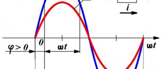
And yes, it would be a big assumption to assume that the valve flows in one direction and not in the other. In fact, everything is somewhat more complicated. In fact, the valve has a certain elasticity of the spring, and so until the direct pressure overcomes this spring, there will be no flow, even in the forward direction.
This is equally true for a diode. The diode has such a parameter as voltage drop. For Schottky diodes it is about 0.2…0.4 volts, and for conventional diodes it is about 0.6…0.8 volts.
Three simple conclusions follow from this knowledge.
1) In order for current to flow through the diode, the voltage across the diode must be higher than its voltage drop.
2) No matter what current flows through the diode, there will always be a voltage across it approximately equal to its voltage drop (that’s why it’s called that way). Those. The diode resistance is nonlinear and decreases with increasing current.
3) By connecting a diode in series with the load, we will lose a voltage across the load equal to the voltage drop of the diode. Those. If you put a diode in a 4.5 volt battery to protect against polarity reversal, you will lose 0.7 volts from the batteries, which is quite significant. Your device will stop working much sooner than the batteries actually run out. And the batteries will not be completely drained. In this case, it is better to install a Schottky diode. It has a lower drop than a simple one (but it has its own jokes). Or better yet, a field-effect transistor.
Let there be a graph too:
This is the current-voltage characteristic of the diode. Which clearly shows that it opens at approximately 0.7 volts. Before this, the current is practically zero. And then it grows parabolically upward with increasing voltage. The resistor's current-voltage characteristic would be linear in direct accordance with Ohm's law. And it’s not that the diode does not pass into the return line, but the current there is very insignificant, fractions of a milliampere. But after a certain voltage, the diode suddenly breaks through and it begins to open, the voltage drop is set somewhere at the level of the reverse voltage limit, and then it completely burns out. After all, an increase in current and a large voltage drop across the diode mean large thermal losses (P=U*I). But the diode is not designed for them. So it usually burns out after a breakdown. But if you limit the current or exposure time so that the thermal power does not exceed the design value, then the electrical breakdown is reversible. But this only applies to ordinary diodes, not Schottky ones. Those break through immediately and completely.
And here is the real characteristics of the Vishay 1N4001 diode
Direct current-voltage characteristic, one quadrant is shown, working. It starts somewhere at 0.6 volts. At the same time, the current there is negligible. And then, with increasing voltage, the diode begins to open sharply. At 0.8 volts the current is already 0.2A, at 1 volt it is already 2.5A and so on until it burns out 
Here is the answer to the question why LEDs cannot be connected in series to a voltage source without current limitation. It seems that the falls have been compensated, so what will happen to them? And the slightest change in voltage causes a sharp change in current. But power supplies are never ideal and power supply variations are always present. Including temperature and load.
And the reverse I-V characteristic, the voltage as a percentage of the maximum (since the datasheet is for the entire family of diodes, from 4001 to 4007 and they have different reverse voltages). Here the currents are already in microamperes and significantly depend on temperature.
▌Selection of diodes. Quick estimates.
To a first approximation, a diode has three interesting parameters - reverse voltage, limiting current and voltage drop.
Those. If you are making a rectifier for a network device, then a diode would be good for 400 volts, or better yet 600 volts of reverse breakdown voltage. So that there is a good supply.
With the limiting current everything is also simple. It should be no less than what will flow through it. It is better to have a reserve of 30 percent.
Well, the drop usually needs to be taken into account for low voltages, battery power.
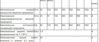
We open the datasheet for... let it be 1N4007 (an ordinary ordinary diode) and look for the required parameters. And immediately we see what we are looking for, a table of maximum values Maximum Rating or something like this:
IF(AV)
direct current. It is always indicated something like this. There's 1A here. The maximum current that this diode carries and does not die. It pulses up to 30A for 8.3ms (IFSM), let’s say it will survive the charge of the capacitors.
The reverse voltage limit is determined by the parameters: VRRM
— repeating peak value.
VRMS
is the effective value of a sinusoidal alternating voltage.
In the West it is customary to call it root mean square. We are also gradually coming to this designation. VDC
- and simply reverse DC voltage.
Well, we look at the drop according to the graphs in the same datasheet for a specific current.
There are also Schottky diodes, they have a smaller internal capacitance and therefore, first of all, they close much faster, which is important for pulse converters operating at high frequencies. And secondly, they have a voltage drop three times lower. But they have low reverse breakdown voltage. A classic Schottky diode looks like this from datasheets:
This is the 1N5819 standing in Pinboard II in the converter:
The voltage drop can be measured with a multimeter in diode test mode.
It shows the drop in volts. And this drop must be taken into account, especially in low-current circuits. For example, you use a diode to decouple some pin of a microcontroller from the signal leaving it. For example, so that when connecting a device to the controller, nothing unnecessary flows.
And the controller itself (MK) must supply a logical unit to the HZ device. And, let's say, it gives it as 3.3 volts. And if the diode drop is 0.6 volts and you have up to H.Z. it will reach not 3.3 volts, but less. And here the question arises: will H.Z. accept it? is it like a logical unit? Will this be correct? Well, and, accordingly, solve problems if not.
All this applies to LEDs to the same extent. Only their voltage drop is much higher and depends on the color. Also, if you want to correctly calculate the resistor limit for an LED, then measure its voltage drop. Subtract the voltage drop of the LED (or LED circuit) from the power supply, and then use the resulting voltage to calculate the resistance using Ohm’s law.
For example, we have an LED with a drop of 3 volts. Its rated current is 10mA, and our power supply is 5 volts. So 5-3 = 2 volts. Now you need to select a resistor for these two volts so that the current is 10mA. 2 / 0.01=200 ohm.
It is especially important to select the correct resistance for flashlights of different optocouplers and other optical sensors. Otherwise the characteristics are not predictable.
Therefore, by the way, you cannot turn on LEDs in parallel with a common current-limiting resistor. Because diodes have a variation in characteristics, even if they are from the same batch. And due to the slightest difference from its neighbors, the difference in current through one diode can be quite significant. As a result, one of the diodes will work with overheating, overheat and burn out. A current-limiting resistor is placed on each diode.
In the second part of this article, which has already been written, the remaining parameters will be described in more detail and why they are formed based on the semiconductor design of the diode. In the meantime, I’ll draw pictures...
Device
A semiconductor electrical diode or diode valve is a device that is made of semiconductor materials (usually silicon) and operates only with a one-way flow of charged particles. The main component is the crystal part, with a pn junction, which is connected to two electrical contacts. Vacuum diode tubes have two electrodes: a plate (anode) and a heated cathode.
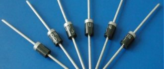
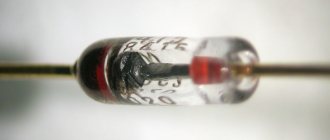
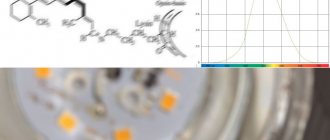
Photo - semiconductor diode
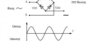
Germanium and selenium are used to create semiconductor diodes, just as they were more than 100 years ago. Their structure allows the parts to be used to improve electronic circuits, convert alternating and direct current into unidirectional pulsating current, and to improve various devices. In the diagram it looks like this:
Photo - diode designation
There are different types of semiconductor diodes, their classification depends on the material, operating principle and area of use: zener diodes, pulsed, alloy, point, varicaps, laser and other types. Quite often analogues of bridges are used - these are planar and polycrystalline rectifiers. Their communication is also carried out using two contacts.
The main advantages of a semiconductor diode:
- Full interchangeability;
- Excellent throughput parameters;
- Availability. You can buy them at any electrical goods store or remove them for free from old circuits. The price starts from 50 rubles. Our stores offer both domestic brands (KD102, KD103, etc.) and foreign ones.
Application area
The scope of use of these parts in modern radio engineering is high. It is difficult to find a device that works without these parts. To understand why a diode is needed, here are a few examples:
- Diode bridges - contain from 4 to 12 semiconductor devices that are connected to each other. The main task of diode bridges is to rectify current, and they are actively used, for example, in creating generators for cars.
- Detectors - created by combining diodes and capacitors. As a result, it becomes possible to isolate low-frequency modulation from various signals. Used in the manufacture of radio and television receivers.
- Protective devices - allow you to protect the electrical circuit from possible overloads. Several products are connected in the opposite direction. When the circuit is working normally, they remain in the closed position. As soon as the input voltage reaches critical levels, the device is activated.
- Switches - such systems based on these products allow switching high-frequency signals.
- Spark protection systems - the creation of a shunt-diode barrier allows you to limit the voltage in the electrical circuit. To increase the degree of protection, special current-limiting resistors are used together with semiconductor parts.
These are just a few examples of the use of diodes. They are quite reliable devices that can be used to solve a large number of problems. Most often, these radio components fail due to natural aging or overheating.
If an electrical breakdown of a product occurs, its consequences are rarely irreversible, since the crystal is not destroyed.
Marking
The marking of a semiconductor diode is an abbreviation for the main parameters of the device. For example, KD196V is a silicon diode with a breakdown voltage of up to 0.3 V, a voltage of 9.6, a model of the third development.
- The first letter determines the material from which the device is made;
- Device name;
- A number defining the purpose;
- Device voltage;
- A number that determines other parameters (depending on the type of part).
Video: using diodes
Content
- 1 Large Signal Modeling 1.1 Shockley Diode Model 1.1.1 Example of a Diode-Resistor Circuit
- 1.2.1 Iterative solution
- 1.3.1 Mathematically idealized diode
- 2.1 Resistance
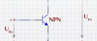
Principle of operation
Semiconductor or rectifier diodes have a fairly simple operating principle. As we have already said, a diode is made of silicon in such a way that one end is p-type and the other end is n-type. This means that both pins have different characteristics. One has an excess of electrons, while the other has an excess of holes. Naturally, there is a region in the device in which all the electrons fill certain gaps. This means that there are no external charges. Due to the fact that this region is depleted of charge carriers and is known as the combining region.