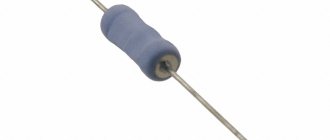
Marking of MLT resistors
The simplest in terms of evaluation is the Soviet resistor, its power rating is marked directly on the case with the marking MLT-1 and so on, where the unit of measurement is power, and MLT is the type of resistors most popular in Soviet times, and this abbreviation means that the resistor is M - metal film, L-varnished, T-heat-resistant. The power of such resistors depends on their size; the larger the resistor, the more power it can dissipate. These resistors are already an endangered species; they can be found in old electronic equipment.
For MLT type resistors, the unit of measurement of resistance, like others, is Ohms, they are designated as R and E. The exact size of power is indicated by the additional letter “K” - kilo-ohms or the letter “M” - mega-ohms, the measurement system here is quite simple. For example: 33E is 33 Ohms, and 47K is 47 kOhms, respectively, 1M2 is 1.2 Megaohms and so on.
An example of the designation of MLT resistors:
Designation of resistors on circuit diagrams.
On circuit diagrams, fixed resistors, regardless of their type, are depicted as a rectangle
, and the resistor terminals are depicted as lines drawn from the sides of the rectangle. This designation is accepted everywhere, but in some foreign circuits the designation of a resistor in the form of a toothed line (saw) is used.
R” is placed next to the symbol
" and the serial number of the resistor in the circuit, and also indicate its nominal resistance in units of Ohm, kOhm, MOhm.
The resistance value from 0 to 999 Ohms is indicated in ohms
, but do not put a unit of measurement:
15
— 15 Ohm
680
– 680 Ohm
920
— 920 Ohm
R is used to denote Ohm
:
1R3
— 1.3 Ohm
33R
– 33 Ohm
470R
— 470 Ohm
Resistance values from 1 to 999 kOhm are indicated in kiloohms
with the addition of the letter "
k
":
1.2k
— 1.2 kOhm
10k
— 10 kOhm
560k
— 560 kOhm
Resistance values of 1000 kOhm and more are indicated in units of megaohm
with the addition of the letter "
M
":
1M
— 1 MΩ
3.3 M
— 3.3 MΩ
56 M
— 56 MΩ
A resistor is used according to the power for which it is designed and which it can withstand without the risk of being damaged when electric current passes through it. Therefore, on the diagrams inside the rectangle, symbols are written indicating the power of the resistor: a double slash indicates a power of 0.125 W; a straight line along the resistor icon indicates a power of 0.5 W; Roman numerals indicate power from 1 W and above.
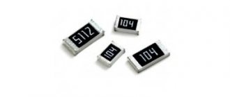
Marking of SMD resistors - designations and explanation
Marking of SMD resistors
The term “SMD resistor” appeared relatively recently. Surface Mounted Devices can literally be translated into Russian as “surface-mounted device.” Chip resistors, as they are also called, are used in surface-mounted printed circuit boards. They have much smaller dimensions than similar wirewound resistors. Square, rectangular or oval shape and low rise allow you to compactly place circuits and save space.
The case has contact pins, which during installation are attached directly to the tracks of the printed circuit board. This design makes it possible to fasten elements without using holes. Thanks to this, the useful area of the board is used with maximum effect, which allows reducing the dimensions of the devices.
Appearance of SMD resistors
The dimensions and shape of SMD resistors are regulated by the JEDEC regulatory document, which provides recommended sizes. Typically, SMD resistors are marked on the case, containing data on the dimensions of the resistor. For example, digital code 0804 assumes a length of 0.08 inches and a width of 0.04 inches.
If we convert this encoding to the SI system, then this SMD resistor will be designated as 2010. From this marking it can be seen that the length is 2.0 mm and the width is 1.0 mm (1 inch is equal to 2.54 mm).
The required power dissipation determines the chip size. Since it is not possible to place the standard markings found on conventional wire-wound resistors on an SMD resistor, which has a very small size, a code designation system has been developed. For convenience, manufacturers have conventionally divided chip resistors into three types according to the marking method:
- three-digit marking;
- four-digit marking;
- marking consisting of two numbers and a letter.
The latter option is used for high-precision resistors with a tolerance of 1% (precision). The very small size does not allow markings with long codes to be placed on them. The EIA-96 standard has been developed for them
To mark small resistances (less than 10 Ohms), the Latin letter “R” is used. For example: 0R1 = 0.1 Ohm and 0R05 = 0.05 Ohm.
Marking of SMD resistors
There are ratings of increased accuracy (so-called precision).
Marking of precision SMD resistors
An example of selecting the required resistor: if the number 232 is indicated, then you need to multiply 23 by 10 to the second power. This results in a resistance of 2.3 kΩ (23 x 102 = 2,300 Ω = 23 kΩ). Chips of the second type are calculated similarly.
SMD resistor designation calculator
Decoding the designation of chip resistors is a specific task. You can calculate the required value using old proven methods by performing several arithmetic operations. But progress does not stand still, and the same can be done using various sites.
The SMD resistor calculator will help you choose the right size, understand the codes, and also save you from grueling calculations. In addition, there is a special program “Resistor”. By clicking the mouse a couple of times, you can find the information you need.
Types of resistors
Despite the simplicity of the operating principle, there are a number of device classifications. According to the installation method, they are distinguished:
- Terminals are one of the most popular options; fastening is carried out through the base of the electrical board; used if the use of new SMD technology is impractical or impossible;
- SMD – the next “generation” of resistors; elements of this type do not have lateral “antennae”; are used when assembling motherboards using robotic systems - the technology is simpler, the fastening is more reliable.
SMD resistor
In addition, the method of manufacturing the device is taken into account. The following options are available:
- Wire - the main element is wire winding in a bifilar manner; metal is used with low resistivity and the ability to withstand high temperatures;
- Metal film, composite – the basis is films made of certain alloys (manganin, nickel, nichrome, carbon, metal oxides and others).
Metal film resistors
Important! The film in models of the latter type is wound in different thicknesses (thin or thick). The technology is used for SMD type elements and chips
An additional division is based on the design and assembly. The following options are possible:
- Constant - the resistance power is set at the factory during assembly and does not change during use;
- Variables – “tuning” type models, equipped with an additional control unit that regulates the resistance power;
- Nonlinear - the parameters are not manually adjusted, but depend on external data (temperature, voltage, light and others).
In addition, there are specialized current models - high-resistance, with an increased level of operating frequency, precision (allowing you to calculate more accurate data).
SMD resistor marking table (code/nominal/size/power) table
SMD resistors marking table:
| Code | Nominal, W | Size | Power V |
| 0402 | 0.062 | Length 1.0 ±0.1, width 0.5 ±0.05, height 0.35 ±0.05 | 100 |
| 0603 | 0.1 | Length 1.6 ±0.1 width 0.85 ±0.1 height 0.45 ±0.05 | 100 |
| 0805 | 0.125 | Length 2.1±0.1 width 1.3 ±0.1 height0.5 ±0.05 | 200 |
| 1206 | 0.25 | Length 3.1 ±0.1 width1.6 ±0.1 height0.55 ±0.05 | 400 |
| 1210 | 0.33 | Length 3.1 ±0.1 width 2.6 ±0.1 height0.55 ±0.05 | 400 |
| 2010 | 0.75 | Length 5.0 ±0.1 width 2.5 ±0.1 height 0.55 ±0.05 | 400 |
| 2512 | 1 | Length 6.35 ±0.1 width 3.2 ±0.1 height 0.55 ±0.05 | 400 |
| 0075 | 0,02 | Length 0.3 Width 0.15 | 100 |
| 01005 | 0,03 | Length 0.4 Width 0.2 | 100 |
| 0201 | 0,05 | Length 0.6 Width 0.3 | 100 |
| 1218 | 1 ; 1,5 | Length 3.2 Width 4.8 | 150 |
| 1812 | 0,5; 0,75 | Length 4.5 Width 3.2 | 200 |
Today there are a huge number of highly specialized parts that differ in their advantages and disadvantages. For example, there are capacitors that can operate at high temperatures, almost 230 °C, there are those that are designed to work in aggressive environments, and milliohm chip resistors have also appeared. There are capacitors that can only be used in certain circuits. The table above indicates standard options, but actual power dissipation may vary.
Types of resistors
Types of resistors for general use include constants, the resistance of which cannot be changed, and variable, when it is permissible to change it within acceptable values. The dissipation power will be in the range of 0.125-100 W, and the resistance will not exceed 10 megaohms.
Permanent
Permanent conductors are distinguished by the presence of only two terminals and constant resistance. Since this type is intended only to reduce the current, it does an excellent job in various electrical appliances. Permanent elements are divided into general and special purpose.
Variables
The variables have three outputs, and in the diagram you can see the boundary values of the operating mode. A slider that moves along the resistive layer will help you change the resistance. During movement, the resistance drops between the middle and one of the side terminals, and accordingly increases on the other side. Variable resistors are divided into trimming and adjusting.
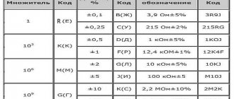
Decoding the markings of Soviet resistors
Color coding of resistors
The marking of Soviet resistors MLT-1 and MLT-2 has an alphanumeric designation and contains:
- two numbers and a letter;
- three numbers and a letter.
Letter code:
- ohms – R or E;
- kilo-ohms – K;
- megaohms - M.
The order of the digital code:
- the denomination from the whole number was placed before the letter - 33K (33 ohms);
- a value less than one was placed after the letter - R 27 (0.27 ohm), M68 (0.68 MOhm or 680 KOhm);
- the denomination of a whole number with a decimal fraction was divided into two parts - the whole number before the letter, the decimal fraction after - 5K6 (5.6 KOhm).
Another number on the case indicated a deviation from the resistance rating.
MLT-1
A code was applied to the body, which indicated:
- MLT – metal film resistor with a heat-resistant varnish layer;
- 1 – power dissipation in watts;
- 47K – resistance 47 Kom;
- 5% – permissible deviation from the nominal value of 5%.
Other
The small size of the case of resistors with a power of less than 0.25 watts did not allow the application of an alphanumeric code, so they were marked with four stripes (rings) of different colors.
The first stripe was applied closer to the edge of the resistor, the rest so as not to make it difficult to read the code.
The color stripes were located from left to right and indicated:
- First, second - face value.
- The third is the multiplier.
- The fourth is the deviation from the nominal value in %.
Each digit from 0 to 9 was color coded:
- black – 0;
- brown – 1;
- red – 2;
- orange – 3;
- yellow – 4;
- green – 5;
- blue – 6;
- purple – 7;
- gray – 8;
- white – 9.
After the numbers there was a strip symbolizing the decimal factor - by which you need to multiply the number formed by the first two stripes:
- silver – 0.01;
- gold – 0.1;
- black – 10;
- brown – 100;
- red – 1000;
- orange – 10000;
- yellow – 100,000;
- green – 10,000,000;
- blue – 1,000,000;
- purple – 10,000,000;
- gray – 100,000,000;
- white – 1000,000,000.
General provisions
In accordance with GOST 28883-90 and the international standard, the resistance of resistors is marked in the form of colored rings. Each colored ring corresponds to a specific digital code. Markings with three stripes are used for resistors with an accuracy of 20%, with four stripes - with an accuracy of 5% and 10%, with five - with an accuracy of up to 0.005%. The sixth strip on the resistor shows the temperature coefficient of resistance (TCR). The color markings on the resistors are shifted to one of the terminals and can be read from left to right. The first stripe is the one closest to the resistor terminal. If, due to the small size of the resistor, the color marking cannot be moved to one of the terminals, then the first sign is made in a strip with a width approximately twice as wide as the others. The color marking of resistors from foreign manufacturers, which are most widespread in our country, most often consists of four color rings. The resistance of the resistor is determined by the first three rings. The first two rings are numbers, and the third ring is the multiplier. The fourth ring represents the permissible deviation of the resistor's resistance from its nominal value.
Color coding of 3-band resistors.
The color of the first two stripes indicates the first digits of the resistance. The third line means a multiplier in the form of a power of ten, by which you need to multiply a number consisting of the first two digits. The accuracy of resistors with 3 bands is 20%.
The resistance of a three-band resistor can be found using the formula:
R=(10A+B)10C,
where R is the resistor resistance, Ohm; A – color number of the first stripe; B – color number of the second stripe; C – color number of the third stripe.
Color coding of 4-band resistors.
The color of the first two stripes indicates the first digits of the resistance. The third line means a multiplier in the form of a power of ten, by which you need to multiply a number consisting of the first two digits. The fourth bar indicates the percentage accuracy of the resistor. It can be silver or golden in color, which means a tolerance of 10% or 5%, respectively.
The resistance of a four-band resistor can be found using the formula:
R=(10A+B)10C,
where R is the resistor resistance, Ohm; A – color number of the first stripe; B – color number of the second stripe; C – color number of the third stripe.
Color coding of 5 band resistors.
The color of the first three stripes indicates the resistance numbers. The fourth line means a multiplier in the form of a power of ten, by which you need to multiply a number consisting of the first three digits. The fifth bar indicates the accuracy of the resistor in percentage.
The resistance of a five-band resistor can be found using the formula:
R=(100A+10B+C)10D,
where R is the resistor resistance, Ohm; A – color number of the first stripe; B – color number of the second stripe; C – color number of the third stripe; D – color number of the fourth stripe.
Color coding of 6 band resistors.
The color of the first three stripes indicates the resistance numbers. The fourth line means a multiplier in the form of a power of ten, by which you need to multiply a number consisting of the first three digits. The fifth bar indicates the accuracy of the resistor in percentage. The sixth band indicates the temperature coefficient of resistance.
The resistance of a six-band resistor can be found using the formula:
R=(100A+10B+C)10D,
where R is the resistor resistance, Ohm; A – color number of the first stripe; B – color number of the second stripe; C – color number of the third stripe; D – color number of the fourth stripe.
How to choose the right SMD resistor
SMD marking
Resistors, which are manufactured using surface mount device technology, or SMD for short, are installed on the surface of the board, most often attached to printed conductors using a soldering iron. The technology of just such installation has made it possible to automate the installation of components, using different soldering methods. Using SMD capacitors, you can reduce the size of the equipment, as well as reduce the time for manufacturing the element.
Considering that there are many varieties, you need to know how to choose them. First of all, it is worth appreciating their advantages and disadvantages. Also, you cannot select a component without knowing the specifics of its application and the area in which it may be useful.
Considering each resistor individually, we can say that it is a two-terminal component that is used to limit current, distribute voltage and form the timing characteristics of the circuit. Along with passive components, active components are used - these are operational controllers, integrated circuits, which are necessary to control and implement bias, filtering and input-output.
If variable capacitors are used, they are needed solely to change the parameters of the circuit. Such components are current sensitive and measure voltage in circuits. As for the material from which they can be made, the choice is also huge; they are used for manufacturing: metal foil, ceramics, varistor, metal, there are photoresistors.
Naturally, it is best to choose the most accurate components that differ in performance characteristics and select dimensions. It should be clearly understood that no matter what technical characteristics are used to increase power, there is also such a thing as heat removal. Some parts can operate at high temperatures, but the heat energy must be removed. Then, in addition to such resistors, additional requirements are imposed regarding mounting on the board. Most often, contacts of copper conductors are used to dissipate heat; due to this, the surface of the board can be cooled.
It happens that in printed circuit boards, the thickness of the board is allocated for surface mounting of elements and special copper polygons are installed, which act as a radiator. Sometimes it turns out that it is impossible to do otherwise than to use forced external cooling, for example, installing micro fans. Among the large selection, you should choose the component that is needed.
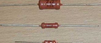
Description of MLT resistors
A fixed resistor is used to ensure the normal operation of electrical circuit components as a current limiter, voltage divider, shunt or load; it is mounted in a wall-mounted manner.
What they look like
A metal film resistor consists of a ceramic tubular base coated with a thin layer of metallized film of a special resistive material. The value of the resistance ratings depends on the composition of the film and the number of turns of the spiral cut on a ceramic base.
Along the edges of the tubular base there are brass caps with silver-plated copper wire leads for installation in the circuit.
To protect against mechanical damage, the current-carrying layer is covered with moisture-resistant organic enamel with markings applied to it.
Most often, the enamel coating is red with alphanumeric or color markings applied to it.
What features do
According to the manufacturing method, MLT resistors can be either with a spiral groove or unthreaded. The most reliable are considered to be non-threaded ones, the ohmic resistance of which is up to 2 kOhm.
During operation, all resistors heat up, dissipating the generated heat. The location of low-power metal-film resistors next to more powerful ones causes intense heating and premature failure of the element - the location of resistive elements at a distance of two diameters between them is considered optimal.
Important! The housing of metal film resistors is not insulated, therefore touching the chassis or live parts is not allowed due to the possibility of a short circuit and breakdown of the resistive element.
The operational reserve of Soviet resistances is large, but they are subject to aging - during long-term storage in a heated room, the conductive layer oxidizes and crystallizes, and the protective coating hardens.
Attention! Natural aging manifests itself in a significant change in nominal characteristics and can lead to rapid failure of the resistance during operation.
When and by whom were they produced?
Metal film resistors were produced from 1964 to 1993 - these were the most popular resistors in the USSR, which are still used by many radio amateurs.
Soviet industrial plants producing metal film resistors - Nizhny Novgorod (now NPO ERKON), Kermet in the Penza region.
Internal structure
The main load-bearing element of the resistor is a substrate made of aluminum oxide (Al2O3). This material has good dielectric properties, but in addition it has very high thermal conductivity, which is necessary to remove the heat generated in the resistive layer into the environment.
Internal structure of the resistor.
The main (but not all) electrical characteristics of a resistor are determined by the resistive element, which is most often a film of metal or oxide, for example, pure chromium or ruthenium dioxide, deposited on a substrate.
The composition, technology of application to the substrate and the nature of processing of this film are the most important elements that determine the characteristics of the resistor, and most often represent the manufacturing secret of the manufacturer.
Some types - wire resistors - use thin (up to 10 microns) wire made of a material with a low temperature coefficient of resistance (for example, constantan) wound on a substrate as a resistive material. In the latter case, the resistor value usually does not exceed 100 Ohms.
To connect the resistive element to the conductors of the printed circuit board, several layers of contact elements are used. The inner contact layer is usually made of silver or palladium, the intermediate layer is a thin film of nickel, and the outer layer is lead-tin solder.
This complex contact structure is designed to ensure reliable mutual adhesion of the layers. Its characteristics, such as reliability and current noise, depend on the quality of the contact elements of the resistor. The last element of the SMD resistor design is a protective layer, which ensures the protection of all elements of the resistor structure from the effects of environmental factors, and primarily from moisture. This layer is made of glass or polymer materials.
Fixed resistance resistors (fixed resistors).
unchanged during operation.
. Structurally, such a resistor is a ceramic tube, on the surface of which a conductive layer is applied, which has a certain ohmic resistance. Metal caps are pressed along the edges of the tube, to which resistor leads made of tinned copper wire are welded. The top of the resistor housing is covered with moisture-resistant colored enamel.
The ceramic tube is called a resistive element
and depending on the type of conductive layer applied to the surface, resistors are divided into
non-wire
and
wire
.
2.1. Non-wire resistors.
Non-wire resistors are used to operate in electrical circuits of direct and alternating current, in which relatively small load currents flow. The resistive element of the resistor is made in the form of a thin semiconducting film
, applied to a ceramic base.
The semiconducting film is called resistive layer
and is made from a film of a homogeneous substance with a thickness of 0.1 - 10 microns (micrometer) or from
microcompositions
. Microcompositions can be made of carbon, metals and their alloys, oxides and compounds of metals, and also in the form of a thicker film (50 microns) consisting of a crushed mixture of a conductive substance.
Depending on the composition of the resistive layer, resistors are divided into carbon, metal-film (metallized), metal-dielectric, metal-oxide and semiconductor. The most widely used are metal film and carbon composite fixed resistors. Domestic resistors include MLT, OMLT (metalized, enamel-lacquered, heat-resistant), BC (carbon) and KIM, TVO (composite).
Non-wire resistors are characterized by their small size and weight, low cost, and the ability to be used at high frequencies up to 10 GHz. However, they are not stable enough, since their resistance depends on temperature, humidity, applied load, operating time, etc. But still, the positive properties of non-wire resistors are so significant that they are the ones that are most widely used.
2.2. Wirewound resistors.
Wirewound resistors are used in DC electrical circuits. When making a resistor, a thin wire made of nickel, nichrome, constantan or other alloys with high electrical resistivity is wound onto its body in one or two layers. The high resistivity of the wire allows the resistor to be made with minimal consumption of materials and small dimensions. The diameter of the wires used is determined by the current density passing through the resistor, technological parameters, reliability and cost, and starts from 0.03 - 0.05 mm.
To protect against mechanical or climatic influences and to secure the turns, the resistor is coated with varnishes and enamels or sealed. The type of insulation affects the heat resistance, dielectric strength and outer diameter of the wire: the larger the diameter of the wire, the thicker the insulation layer and the higher the dielectric strength.
The most widely used wires are enamel insulation PE (enamel), PEV (high-strength enamel), PETV (heat-resistant enamel), PETK (heat-resistant enamel), the advantage of which is its small thickness with a fairly high electrical strength. Common high-power resistors are enameled wire resistors such as PEV, PEVT, S5-35, etc.
Compared to non-wire resistors, wire resistors are more stable. They can operate at higher temperatures and withstand significant overloads. However, they are more difficult to manufacture, more expensive and unsuitable for use at frequencies above 1-2 MHz, since they have high intrinsic capacitance and inductance, which manifest themselves already at frequencies of several kilohertz.
Therefore, they are mainly used in DC or low-frequency circuits, where high accuracy and stability of operation are required, as well as the ability to withstand significant overload currents that cause significant overheating of the resistor.
With the advent of microcontrollers, modern technology has become more functional and at the same time much smaller. The use of microcontrollers has made it possible to simplify electronic circuits and thereby reduce the current consumption of devices, which has made it possible to miniaturize the element base. The figure below shows SMD resistors that are soldered to the board from the printed circuit board side.
SMD resistors - marking the nominal values of SMD resistors
SMD resistors - marking of chip resistors
SMD resistors - the markings of which are of interest to many radio amateurs. These resistors are manufactured in miniature packages, usually made of ceramic and intended for surface mounting. This element is the most common component in modern electronic circuits.
Various companies producing SMD resistors make many different modifications of their products, code designations of which differ from others. In this regard, electronics engineers who often have to repair electronic equipment or assemble printed circuit boards need to clearly know the code designations of resistors.
Purpose of chip resistors
The main function of resistors in a circuit is to limit current in a specific part of the electrical path. One of the closest examples that can be used to show a resistor in action is the inclusion of resistance in the supply circuit of LED diodes or in the emitter circuit of a bipolar transistor installed in the amplifying stage. The table below will greatly assist you in deciphering the codes.
Table of decoding nominal values of SMD resistors
| Code smd | Meaning | Code smd | Meaning | Code smd | Meaning | Code smd | Meaning |
| R10 | 0.1 Ohm | 1R0 | 1 ohm | 100 | 10 ohm | 101 | 100 Ohm |
| R11 | 0.11 Ohm | 1R1 | 1.1 Ohm | 110 | 11 ohm | 111 | 110 Ohm |
| R12 | 0.12 Ohm | 1R2 | 1.2 Ohm | 120 | 12 ohm | 121 | 120 Ohm |
| R13 | 0.13 Ohm | 1R3 | 1.3 Ohm | 130 | 13 ohm | 131 | 130 Ohm |
| R15 | 0.15 Ohm | 1R5 | 1.5 Ohm | 150 | 15 ohm | 151 | 150 Ohm |
| R16 | 0.16 Ohm | 1R6 | 1.6 Ohm | 160 | 16 ohm | 161 | 160 Ohm |
| R18 | 0.18 Ohm | 1R8 | 1.8 Ohm | 180 | 18 ohm | 181 | 180 Ohm |
| R20 | 0.2 Ohm | 2R0 | 2 ohm | 200 | 20 ohm | 201 | 200 Ohm |
| R22 | 0.22 Ohm | 2R2 | 2.2 Ohm | 220 | 22 Ohm | 221 | 220 Ohm |
| R24 | 0.24 Ohm | 2R4 | 2.4 Ohm | 240 | 24 ohm | 241 | 240 Ohm |
| R27 | 0.27 Ohm | 2R7 | 2.7 Ohm | 270 | 27 Ohm | 271 | 270 Ohm |
| R30 | 0.3 ohm | 3R0 | 3 ohm | 300 | 30 ohm | 301 | 300 Ohm |
| R33 | 0.33 Ohm | 3R3 | 3.3 Ohm | 330 | 33 Ohm | 331 | 330 Ohm |
| R36 | 0.36 Ohm | 3R6 | 3.6 Ohm | 360 | 36 Ohm | 361 | 360 Ohm |
| R39 | 0.39 Ohm | 3R9 | 3.9 Ohm | 390 | 39 Ohm | 391 | 390 Ohm |
| R43 | 0.43 Ohm | 4R3 | 4.3 Ohm | 430 | 43 Ohm | 431 | 430 Ohm |
| R47 | 0.47 Ohm | 4R7 | 4.7 Ohm | 470 | 47 Ohm | 471 | 470 Ohm |
| R51 | 0.51 Ohm | 5R1 | 5.1 Ohm | 510 | 51 Ohm | 511 | 510 Ohm |
| R56 | 0.56 Ohm | 5R6 | 5.6 Ohm | 560 | 56 Ohm | 561 | 560 Ohm |
| R62 | 0.62 Ohm | 6R2 | 6.2 Ohm | 620 | 62 Ohm | 621 | 620 Ohm |
| R68 | 0.68 Ohm | 6R8 | 6.8 Ohm | 680 | 68 Ohm | 681 | 680 Ohm |
| R75 | 0.75 Ohm | 7R5 | 7.5 Ohm | 750 | 75 Ohm | 751 | 750 Ohm |
| R82 | 0.82 Ohm | 8R2 | 8.2 Ohm | 820 | 82 Ohm | 821 | 820 Ohm |
| R91 | 0.91 Ohm | 9R1 | 9.1 Ohm | 910 | 91 Ohm | 911 | 910 Ohm |
| Code smd | Meaning | Code smd | Meaning | Code smd | Meaning | Code smd | Meaning |
| 102 | 1 kOhm | 103 | 10 kOhm | 104 | 100 kOhm | 105 | 1 MOhm |
| 112 | 1.1 kOhm | 113 | 11 kOhm | 114 | 110 kOhm | 115 | 1.1 MOhm |
| 122 | 1.2 kOhm | 123 | 12 kOhm | 124 | 120 kOhm | 125 | 1.2 MOhm |
| 132 | 1.3 kOhm | 133 | 13 kOhm | 134 | 130 kOhm | 135 | 1.3 MOhm |
| 152 | 1.5 kOhm | 153 | 15 kOhm | 154 | 150 kOhm | 155 | 1.5 MOhm |
| 162 | 1.6 kOhm | 163 | 16 kOhm | 164 | 160 kOhm | 165 | 1.6 MOhm |
| 182 | 1.8 kOhm | 183 | 18 kOhm | 184 | 180 kOhm | 185 | 1.8 MOhm |
| 202 | 2 kOhm | 203 | 20 kOhm | 204 | 200 kOhm | 205 | 2 MOhm |
| 222 | 2.2 kOhm | 223 | 22 kOhm | 224 | 220 kOhm | 225 | 2.2 MOhm |
| 242 | 2.4 kOhm | 243 | 24 kOhm | 244 | 240 kOhm | 245 | 2.4 MOhm |
| 272 | 2.7 kOhm | 273 | 27 kOhm | 274 | 270 kOhm | 275 | 2.7 MOhm |
| 302 | 3 kOhm | 303 | 30 kOhm | 304 | 300 kOhm | 305 | 3 MOhm |
| 332 | 3.3 kOhm | 333 | 33 kOhm | 334 | 330 kOhm | 335 | 3.3 MOhm |
| 362 | 3.6 kOhm | 363 | 36 kOhm | 364 | 360 kOhm | 365 | 3.6 MOhm |
| 392 | 3.9 kOhm | 393 | 39 kOhm | 394 | 390 kOhm | 395 | 3.9 MOhm |
| 432 | 4.3 kOhm | 433 | 43 kOhm | 434 | 430 kOhm | 435 | 4.3 MOhm |
| 472 | 4.7 kOhm | 473 | 47 kOhm | 474 | 470 kOhm | 475 | 4.7 MOhm |
| 512 | 5.1 kOhm | 513 | 51 kOhm | 514 | 510 kOhm | 515 | 5.1 MOhm |
| 562 | 5.6 kOhm | 563 | 56 kOhm | 564 | 560 kOhm | 565 | 5.6 MOhm |
| 622 | 6.2 kOhm | 623 | 62 kOhm | 624 | 620 kOhm | 625 | 6.2 MOhm |
| 682 | 6.8 kOhm | 683 | 68 kOhm | 684 | 680 kOhm | 685 | 6.8 MOhm |
| 752 | 7.5 kOhm | 753 | 75 kOhm | 754 | 750 kOhm | 755 | 7.5 MOhm |
| 822 | 8.2 kOhm | 823 | 82 kOhm | 824 | 820 kOhm | 815 | 8.2 MOhm |
| 912 | 9.1 kOhm | 913 | 91 kOhm | 914 | 910 kOhm | 915 | 9.1 MOhm |
Marking of SMD resistors
Characteristics
The most important characteristics of resistors are the value of the nominal resistance, the tolerance for this value and the temperature coefficient of change in resistance.
Closely related to these characteristics are the permissible power dissipation and the thermal resistance between the resistor and the environment. In addition, in some applications of resistors, their noise characteristics (especially current noise) can be significant.
Also, temporary stability, the maximum operating voltage, the dependence of resistance on the applied voltage and the frequency parameters of the resistor (characteristics of its equivalent circuit at various frequencies).
Let's consider the most important of these characteristics from the point of view of the use of resistors in analog and digital-to-analog electronic devices. These are the value of the nominal resistance, the tolerance for this value and the temperature coefficient of change in resistance. The tolerance on the nominal resistance value is specified as a percentage of the nominal resistance value. The nominal value is the resistance value of the resistor, measured at fixed values of external influence factors.
Heating and cooling curve when soldering SMD resistors.
The most important among these factors is temperature. Typically, the nominal resistance value is given for a temperature of +20°C and normal atmospheric pressure. SMD resistors are available with nominal resistance tolerances ranging from ±0.05% to ±5%. Designers should keep in mind that the most common, accessible, and cheapest resistors are those with nominal value tolerances of ±5% and ±1%.
More precise resistors usually require pre-order and their cost increases several times. Temperature coefficient of resistance (TCR) is a value that characterizes the reversible relative change in the resistance of a resistor when its temperature changes by 1°C. It should be borne in mind that a change in the temperature of the resistor can occur both due to changes in ambient temperature and due to its self-heating.
The TCS value is determined by the formula:
TKS=DR/(R*DT)
where DR is the absolute value of the change in resistance when the temperature of the resistor changes by the value DT, R is the nominal value of the resistor resistance.
The TCS value is measured in 1/°C, however, most often it is measured in ppm units (1ppm=10E-6 1/°C). Modern SMD resistors are available with TCR values ranging from ±5 to ±200 ppm.
It is interesting to compare the effect on the overall deviation from the nominal value of the resistor resistance of its tolerance and temperature changes. This comparison can be made by introducing a parameter such as the critical temperature Tk, defined as the change in the temperature of the resistor at which the change in its resistance, determined by the TCR value, becomes equal to the tolerance for the nominal resistance.
Taking into account the small value of the tolerance on the value of the nominal resistance of the resistor, it can be stated with a sufficient degree of accuracy that with the worst combination of tolerances on resistors, the tolerance on the value of K is twice as large as the tolerance on the resistor value.
This means that when using SMD resistors of the highest accuracy in this circuit and without taking into account the influence of heating of the resistors, it is impossible to achieve a transmission coefficient accuracy higher than ±0.1%! This precision is clearly not enough for many analog devices. Fortunately, in reality the situation is somewhat simpler. The fact is that in the given expression for the transmission coefficient, its accuracy is determined not by the absolute values of the resistances of resistors R1 and R3, but by their ratio.
If resistors from the same company and the same batch are used for the circuit, then the values of their TCR and nominal values can be much closer than the passport data for each resistor separately. This allows you to significantly increase the resulting accuracy of the circuit, both at normal temperature and when it changes. However, in practice, applying the proposed approach to reducing the error of circuits is not so easy!
In the circuit discussed above, it only works well when K = -1, since this requires identical resistors, which can be selected from the same batch. For other values of K, this circuit will not provide the required accuracy, since for resistors of different ratings the probability of divergence of parameters (especially TCR) increases significantly.
Chip resistor markings, ratings
After reading the designation of a 2r00 resistor, how can you determine what resistance it is designed for? For this purpose, there is a marking for smd resistors. This can be done using tables that contain a list of characteristics, according to the designation on the case. An online calculator program will also help you decipher the digital markings. The interface of this online tool looks simple and works quickly. All you need to do is enter the required request into the fields.
Online calculator for calculating digital symbols
Upon visual inspection of the element, the marking of SMD resistors may have the following signs printed on the housing:
- digital markings;
- alphabetic characters;
- color markers.
They are applied directly to the top of the body and have different meanings.
Digital markings
The code written on the resistive element may consist of three or four digits. The three-digit designation is easy to decipher. For example, for a resistor 103, how many ohms is the resistance value is indicated by the first two digits, the third is the multiplier by which the two-digit number is multiplied. In mathematics, it is the exponent of a number with a base of 10.
Attention! The multiplier in this case is the power n to which the number 10 must be raised. Therefore, chip resistor 104 has a nominal value of 10 * 104 = 100 kOhm
Marking with three numbers positions elements that have an error tolerance: 2; 5; 10%.
Three-digit numeric designation
Marking of resistors less than 1 ohm
The corresponding mark on the part, as for resistances less than 10 Ohms, requires entering the letter R into the code. It is placed either in front of two digits or in the middle and replaces the decimal point.
Designation of SMD resistors
Color designation
The color method of marking resistors is used for elements that have a small standard size. However, it is not used for SMD resistors. Based on the color palette of the rings, you can determine: denomination, multiplier and temperature coefficient (TC). The colored ring surrounding the element has a specific color, width and location.
Some features when applying color markings that can be interpreted as follows:
- Parts with an error of 20% have 3 rings. The first two are the resistance value, the third is the multiplier.
- Four rings indicate that the tolerance is other than 20% and is indicated by the fourth ring.
- The five colored rings have a different meaning. The first three are the part rating, the fourth is the multiplier value, the fifth is the tolerance value of 0.005%.
TCR, also known as TCR (Temperature Coefficient of Resistance), shows how much the resistance value of a two-terminal network will change when the temperature changes by one degree. Temperature can change in any direction.
The sixth bar (rarely) will indicate the TCR value for the resistor. Use in circuits sensitive to changes in ambient temperature requires the installation of an element with a certain TCR value.
Interpretation of colored markers
Letter marking
The EIA - 96 standard allows the entry of a letter as the third character when encoding resistive SMD chips.
Decoding the mnemonic symbol with letters
With a tolerance requirement of 1%, the markings have three-digit or four-digit designations on the body of the parts.
Two numbers and a letter for such SMD resistors of size 0603 are distributed as follows:
- the first two digits are resistance in Ohms;
- the letter is a multiplier: S, R, B, C, D, E, F.
Resistance data with a three-digit code is determined from tables.
Table of codes for the first two digits with a tolerance of 1%
Numbering using 4 digits with a given tolerance for deviation from accuracy means:
- the first three digits are the mantissa (fractional part of the decimal number);
- The fourth digit is the exponent of the number 10.
For example, a resistive element labeled 3501 has a rating of 350 * 10 = 3.5 kOhm.
Interesting. When a zero “0” is drawn on the part, this means the SMD resistor has a zero resistance value. It's just a jumper. When measured by a tester, the result should not be misleading - the element is working.
When replacing faulty elements located on a printed circuit board, correctly determining the nominal value will help eliminate the damage. If necessary, you can replace SMD components with parts of similar parameters by deciphering the digital and alphabetic codes.
Resistor calculation
To select and install elements in the circuit, you must first calculate the rating and power of the components.
Formula for calculating resistance and power
Use Ohm's Law for a section of the circuit to calculate the resistance of the resistor, the formula is:
R = U/I,
Where:
- U – voltage at the terminals of the element, V;
- I – current strength in a section of the circuit, A.
This formula is applicable for currents of constant direction. In the case of calculations for alternating current, the circuit impedance Rz is taken into account.
Important! The structure of the circuits is not limited to installing only one resistor. Usually there are many of them, they are connected to each other in parallel and in series
To find the general indicator, separate methods and formulas are used.
Serial connection
With this connection, the “output” of one element is connected to the “input” of another, they go sequentially one after another. How to calculate the resistor in this case? You can use an online electronic calculator, you can apply the formula.
The total value will be the sum of the resistances of the components included in the series connection:
R123 = R1+R2+R3.
Each of them will experience the same voltage drop: U1, U2, U3.
Parallel connection
When performing this type of connection, the terminals of the same name are connected in pairs, the formula looks like:
R = (R1 x R2)/ (R1 + R2).
Usually the resulting R value is less than the smaller of all the values of the connected elements.
Serial and parallel connections
Information. In practice, parallel or series connection is used when there is no part of the required rating. For such cases, elements are selected of the same power and the same type, so as not to get a weak link.
Mixed compound
It is possible to calculate the total resistance of mixed connections by applying the combining rule. First, all parallel and series connections are selected and equivalent equivalent circuits are drawn up. They begin to be calculated using formulas for each case. From the resulting simpler circuit, parallel and serial links are again isolated and calculations are made again. They do this until they get the most elementary compound or one equivalent element. The calculated result will be the desired one.
Calculation method for mixed connection
Power
Finding the resistance value alone is not enough to apply the part. It is necessary to find out what power the element should be designed for. Otherwise, it will overheat and fail. For surface mounting, it is better to install powerful parts on a radiator.
The resistor power is calculated using the formula:
P = I² * R = U²/R,
Where:
- P – power, W;
- I – current, A;
- U – voltage, V;
- R – resistance, Ohm.
After determining the power of the resistors using the formula, components are selected based on the graphic designation on the diagrams.
Basic designations for resistor power
Designation of smd resistors
There are two marking systems or, if you want, designations for resistors.
For example, 0204 = 0.02(length) x 0.04(length) (all in inches).
In another system - metric (metric), the designation is already in millimeters.
For example, 0510 = 0.5 (length) x 1.0 (width) (in millimeters).
And this will be the same 0204 resistor that was in inches. In order to confuse one system with another, in technical documentation for the metric system the letter M is often added, but not the fact, after the numeric code (say, 0510M).
Now I will provide some very useful background information.
Designation (length, width, power) of the element (resistor).
| In inches | L, length, length (inches) | W, width, width (inches) | Metric | L, length in mm. | W, width in mm. |
| 0050 | 0,008 | 0,004 | 0201M | 0,2 | 0,1 |
| 0075 | 0,012 | 0,006 | 03015M | 0,3 | 0,15 |
| 01005 | 0,016 | 0,008 | 0402M | 0,4 | 0,2 |
| 0201 (02016) | 0,02 | 0,01 | 0603M | 0,6 | 0,3 |
| 0202 | 0,02 | 0,02 | 0605M | 0,6 | 0,5 |
| 0204 | 0,02 | 0,04 | 0510M | 0,5 | 1,0 |
| 0303 | 0,03 | 0,03 | 0808M | 0,8 | 0,8 |
| 0306 | 0,03 | 0,06 | 0816M | 0,8 | 1,6 |
| 0402 | 0,04 | 0,02 | 1005M | 1,0 | 0,5 |
| 0404 | 0,04 | 0,04 | 1010M | 1,0 | 1,0 |
| 0406 | 0,04 | 0,06 | 1016M | 1,0 | 1,6 |
| 0408 | 0,04 | 0,08 | 1020M | 1.0 | 2,0 |
| 0502 | 0,05 | 0,02 | 1406M | 1,4 | 0,6 |
| 0504 | 0,05 | 0,04 | 1210M | 1,2 | 1,0 |
| 0505 | 0,05 | 0,05 | – | 1,2 | 1,2 |
| 0508 | 0,05 | 0,08 | 1220M | 1,2 | 2,0 |
| 0510 | 0,05 | 0,1 | – | 1,2 | 2,5 |
| 0603 | 0,06 | 0,03 | 1608M | 1,6 | 0,8 |
| 0606 | 0,06 | 0,06 | 1616M | 1,6 | 1,6 |
| 0612 | 0,06 | 0,12 | 1632M | 1,6 | 3,2 |
| 0616 | 0,06 | 0,16 | 1640M | 1,6 | 4,0 |
| 0805 | 0,08 | 0,05 | 2012M | 2,0 | 1,25 |
| 0808 | 0,08 | 0,08 | 2020M | 2,0 | 2,0 |
| 0815 | 0,08 | 0,15 | 2037M | 2,0 | 3,7 |
| 0830 | 0,08 | 0,30 | 2075M | 2,0 | 7,5 |
| 1005 | 0,1 | 0,05 | 2512M | 2,5 | 1,2 |
| 1008 | 0,1 | 0,08 | 2520M | 2,5 | 2,0 |
| 1010 | 0,1 | 0,1 | 2525M | 2,5 | 2,5 |
| 1020 | 0,1 | 0,2 | 2550M | 2,5 | 5,0 |
| 1206 | 0,12 | 0,06 | 3216M | 3,2 | 1,6 |
| 1210 | 0,12 | 0,1 | 3225M | 3,2 | 2,5 |
| 1218 | 0,12 | 0,18 | 3245M (3248M) | 3,2 | 4,5-4,8 |
| 1224 | 0,12 | 0,24 | 3250M | 3,2 | 5,0 |
| 1225 | 0,12 | 0,25 | 3264M | 3.2 | 6,4 |
| 1505 | 0,15 | 0,05 | 3812M | 3,8 | 1,2 |
| 1806 | 0,18 | 0,06 | 4516M | 4.5 | 1,6 |
| 1808 | 0,18 | 0,08 | 4520M | 4,5 | 2,0 |
| 1812 | 0,18 | 0,12 | 4532M | 4,5 | 3,2 |
| 1825 | 0,18 | 0,25 | 4564M | 4,5 | 6,4 |
| 2007 | 0,2 | 0,07 | 5320M | 5,3 | 2,0 |
| 2010 | 0,2 | 0,1 | 5025M | 5,0 | 2,5 |
| 2220 | 0,22 | 0,2 | 5750M (5650M) | 5,7-5,6 | 5,0 |
| 2225 | 0,22 | 0,25 | 5664M | 5,6 | 6,4 |
| 2512 | 0,25 | 0,12 | 6432M (6332M) | 6,4-6,3 | 3,2 |
| 3014 | 0,30 | 0,14 | 7836M | 7,8 | 3,6 |
| 3921 | 0,39 | 0,21 | 1052M | 10,0 | 5,2 |
| 4527 | 0,45 | 0,27 | 11070M (11470M) | 11,0-11,4 | 7,0 |
| 5931 | 0,59 | 0,31 | 1577M | 15,0 | 7,75 |
| 6927 | 0,69 | 0,27 | 17570M | 17,5 | 7,0 |
Here it is worth mentioning the following. Despite the fact that we were talking about resistors, an analogy in housings is drawn with other radio elements. Such size designations are also used for ceramic SMD capacitors (2220, 2225, 1825, 0505, 0204, etc.), SMD resistor assemblies, and SMD LEDs.
Types of resistors
Types of resistors can be divided into the following categories:
- Unregulated (permanent) - wire, composite, film, carbon, etc.
- Adjustable (variable and adjustable). Trimmer resistors are designed for tuning electrical circuits. Elements with variable resistance (potentiometers) are used to adjust signal levels.
A separate group is represented by semiconductor resistive elements (thermoresistors, photoresistors, varistors, etc.)
The characteristics of resistors are determined by their purpose and are specified during manufacture. Among the key parameters:
- Nominal resistance. This is the main characteristic of the element, measured in ohms (Ohm, kOhm, MOhm).
- Permissible deviation as a percentage of the specified nominal resistance. Indicates the possible spread of the indicator, determined by the manufacturing technology.
- Power dissipation is the maximum power that a resistor can dissipate under long-term load.
- Temperature coefficient of resistance is a value showing the relative change in the resistance of the resistor when the temperature changes by 1°C.
- Limit operating voltage (electric strength). This is the maximum voltage at which the part maintains its declared parameters.
- Noise characteristic is the degree of distortion introduced by a resistor into the signal.
- Moisture resistance and heat resistance are the maximum values of humidity and temperature, exceeding which can lead to failure of the part.
- Voltage factor. A value that takes into account the dependence of resistance on applied voltage.
The use of resistors in the microwave region makes additional characteristics important: parasitic capacitance and inductance
Online calculator of resistance values of DIP and SMD resistors
Online SMD resistor marking calculator
We present a simple and convenient SMD resistor resistance calculator. To find out the value of your resistor, enter its code in the black field:
Our calculator allows you to determine the resistance of SMD resistors marked according to the EIA-96 standard, according to which 3 or 4 numbers, or 2 numbers and 1 letter are applied to the case.
SMD resistor markings
When using markings with three or four digits, the first 2 or 3 of which indicate the quantitative value of the resistor's resistance, and the last - the multiplier indicator. The multiplier is equal to the power to which the quantity must be raised to obtain the final denomination.
Here are a few examples of determining the value of an SMD resistor based on its marking:
- 473 = 47kΩ ± 5%
- 103 = 10kΩ ± 5%
- 312 = 3.1kΩ ± 5%
- 106 = 10MΩ ± 5%
When marking resistances less than 10Ω, the Letter R is used. It indicates the position of the decimal point:
- 0R5 = 0.5Ω
- 0R3 = 0.3Ω
- 0R7 = 0.7kΩ
For high-precision resistors, the error rate of which is 1%, the letter is placed at the end of the value and is a multiplier. The two numbers at the beginning indicate the code by which the resistance is determined:
- 92Z = 0.89Ω ± 1%
- 32D = 210kΩ ± 1%
- 24E = 1.74MΩ ± 1%
The store offers:
And many many others!
Types of resistors
Resistors are classified according to several criteria.
For discrete elements, division occurs at the installation location:
- introductory. On the circuit board they are mounted through it. The contacts of such nodes are located according to the axial or radial principle. In the language of electronic engineers, they are called legs. This type of resistor has been used for a very long time. They can be found on both old and modern equipment. They replace SMD elements if their use is difficult or absolutely impossible.
- SMD. They are components of an electrical circuit without legs. The terminals are located on the body. Although it is very difficult to call them such, since they protrude to the surface insignificantly. The advantages of such components include low cost, ease of assembly and saving space on the circuit.
The marking of SMD resistors is no different from the input elements. It is also identified by stripes and color.