A diode is one of the types of devices designed on a semiconductor basis. It has one pn junction, as well as anode and cathode terminals. In most cases, it is designed for modulation, rectification, conversion and other actions with incoming electrical signals.
Principle of operation:
- An electric current acts on the cathode, the heater begins to glow, and the electrode begins to emit electrons.
- An electric field is formed between the two electrodes
- If the anode has a positive potential , then it begins to attract electrons to itself, and the resulting field is a catalyst for this process. In this case, an emission current is generated.
- Between the electrodes, a negative spatial charge is formed, which can interfere with the movement of electrons. This happens if the anode potential is too weak. In this case, some of the electrons are unable to overcome the influence of the negative charge, and they begin to move in the opposite direction, returning to the cathode again.
- All electrons that reach the anode and do not return to the cathode determine the parameters of the cathode current. Therefore, this indicator directly depends on the positive anode potential.
- The flow of all electrons that were able to get to the anode is called the anode current, the indicators of which in the diode always correspond to the parameters of the cathode current. Sometimes both indicators can be zero; this happens in situations where the anode has a negative charge. In this case, the field that arises between the electrodes does not accelerate the particles, but, on the contrary, slows them down and returns them to the cathode. The diode in this case remains in a locked state, which leads to an open circuit.
Device
Below is a detailed description of the diode structure; studying this information is necessary for further understanding of the principles of operation of these elements:
- The housing is a vacuum cylinder that can be made of glass, metal or durable ceramic varieties of material.
- inside the cylinder . The first is a heated cathode, which is designed to ensure the process of electron emission. The simplest cathode in design is a filament with a small diameter, which heats up during operation, but today indirectly heated electrodes are more common. They are cylinders made of metal and have a special active layer capable of emitting electrons.
- Inside the indirectly heated there is a specific element - a wire that glows under the influence of electric current, it is called a heater.
- The second electrode is the anode, it is needed to receive the electrons that were released by the cathode. To do this, it must have a potential that is positive relative to the second electrode. In most cases, the anode is also cylindrical.
- Both electrodes of vacuum devices are completely identical to the emitter and base of the semiconductor variety of elements.
- Silicon or germanium is most often used to make a diode crystal One of its parts is p-type electrically conductive and has a deficiency of electrons, which is formed by an artificial method. The opposite side of the crystal also has conductivity, but it is n-type and has an excess of electrons. There is a boundary between the two regions, which is called a pn junction.
Such features of the internal structure give diodes their main property - the ability to conduct electric current in only one direction.
Purpose
Below are the main areas of application of diodes, from which their main purpose becomes clear:
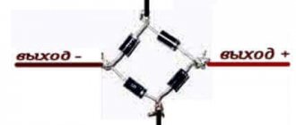
- Diode bridges are 4, 6 or 12 diodes connected to each other, their number depends on the type of circuit, which can be single-phase, three-phase half-bridge or three-phase full-bridge. They perform the functions of rectifiers; this option is most often used in automobile generators, since the introduction of such bridges, as well as the use of brush-collector units with them, has made it possible to significantly reduce the size of this device and increase its reliability. If the connection is made in series and in one direction, this increases the minimum voltage required to unlock the entire diode bridge.
- Diode detectors are obtained by combining these devices with capacitors. This is necessary so that it is possible to isolate low-frequency modulation from various modulated signals, including the amplitude-modulated variety of the radio signal. Such detectors are part of the design of many household appliances, such as televisions or radios.
- Ensuring protection of consumers from incorrect polarity when switching on circuit inputs from occurring overloads or switches from breakdown by electromotive force that occurs during self-induction, which occurs when the inductive load is turned off. To ensure the safety of circuits from overloads that occur, a chain is used consisting of several diodes connected to the supply buses in the reverse direction. In this case, the input to which protection is provided must be connected to the middle of this chain. During normal operation of the circuit, all diodes are in a closed state, but if they have detected that the input potential has gone beyond the permissible voltage limits, one of the protective elements is activated. Due to this, this permissible potential is limited within the permissible supply voltage in combination with a direct drop in the voltage on the protective device.
- Switches based on diodes are used to switch high-frequency signals. Such a system is controlled using direct electric current, high-frequency separation and the supply of a control signal, which occurs due to inductance and capacitors.
- Creation of diode spark protection . Shunt-diode barriers are used, which provide safety by limiting the voltage in the corresponding electrical circuit. In combination with them, current-limiting resistors are used, which are necessary to limit the electric current passing through the network and increase the degree of protection.
The use of diodes in electronics today is very widespread, since virtually no modern type of electronic equipment can do without these elements.
Temperature measurement when upgrading cooling systems for PCs and other electronic devices
Without accurate and high-quality means of measuring temperature, it is difficult to evaluate the results of your work on overclocking, testing thermal interfaces, and measuring the characteristics of the latter. And in general any work involving cooling. I will try here to talk about various sensors for measuring temperature, their advantages and disadvantages. It is sensors, since accuracy (including repeatability of characteristics for different samples of the same model) determines the possibility of their use. And high-quality electronics for linearization and digitization of readings is a matter of the measurement circuit and instrument developers.
Introduction
We are accustomed to measuring temperature in degrees Celsius, where the freezing point of water (0 °C) and the boiling point of water (100 °C) are taken as reference points.
The English scientist Kelvin proposed a universal absolute thermodynamic temperature scale, which has become standard in modern thermometry. He substantiated the concept of absolute zero temperature.
Fahrenheit invented the mercury thermometer and defined a temperature scale for it, where the reference points were the freezing point of the saline solution as zero (0F = -32°C), and the temperature of the human body as 98.2F (36.6°C).
There have been cases when controllers built into the motherboard gave readings in degrees Fahrenheit, which caused a storm of questions from users. Therefore, it is sometimes necessary to convert the temperature value from scale to scale.
To do this, use the formulas:
T(K)=T(°C) + 273.15
T(°C)=(°F - 32)/1.8
Temperature sensors are divided into two groups: contact and non-contact.
The most widely used temperature sensors are contact temperature sensors. This:
thermistor, thermistor, diode operating on forward and reverse current, thermocouple.
Temperature sensors, approximate characteristics.
| Sensor type | Operating temperature range °C | Characteristic | Accuracy % | Supply voltage/current | Interface/signal | Peculiarities |
| Mercury thermometer | +105 | linear | 0.02 °C | No | No | Calibration Tool |
| Semiconductor thermistor (Thermistor) | -60 -:- +125 cm for your type | nonlinear | ±20 -:- ±1 | Limited to Imax | /current, voltage | Thermistor power is limited |
| -200…+300°С | nonlinear | ±5, ±10, ±20 | There are no restrictions in the operating temperature range of the SE | /current, voltage | thermistors based on diamond single crystals | |
| Resistance thermometer | -50 -:- +200 | nonlinear | up to 0.001 | according to your passport | /current | For bridge circuits |
| Reverse (thermal) current diode | <100 | quadratic | large, requires individual adjustment | <rev.max. | /current | Doubling the current for every: 10°С -Si 14°С-Ge |
| Direct current diode | equal to the temperature of Si or Ge structures | close to linear | requires adjustment | /pr.max | /voltage | sensitivity 3mV/°С-Si 2mV/°С-Ge |
| Thermocouple (type L, chromel - alumel) | -180 -:- +1300 | nonlinear | 1.5, standard less than 0.1 | No | /voltage | The use of calibration tables reduces the error to 0.1% |
| Analog temperature sensor TMP35 | +10 -:- +125 | linear | +/- 1 | 2.7-5.5 V | voltage | |
| Digital temperature sensor DS1624 | -55 -:- +125 | linear | 0.03°С | 2.7-5.5 V | I2C | |
| Pyrometer | min -70 max +2200 | Digital device | from 0.5 | 9 V | USB | |
| Thermal imager | -20 -:- +300 | resolution 0.08°С | ±2 °C or ±2% | batteries/adapter 220V | USB /IEEE1394 |
This category of temperature sensors operates when the sensor is in direct contact with the surface of the controlled object. Contact temperature sensors (CTS) are the most common for temperature measurements.
Most of them, when used as part of meters, require calibration, which is performed using high-precision thermometers (standard or laboratory with an accuracy exceeding the expected error of the meter). Some have a certified output current equal to I=k*t, where k is the coefficient that determines the slope angle of the characteristic.
For temperatures of 20 - 100 ºС, calibration of temperature sensors or meters can be performed at home using a simple device. It consists of a vessel with water standing on a heater. Your control device (for example, a mercury thermometer with a division value of 0.1 ºC) is attached to the vessel so that its sensitive part filled with mercury is in the center. Your controlled sensor is fixed to the sensitive part with a thin thread. The vessel is filled with water (to test high-resistance sensors, the water must be distilled). The heater should be of low power to ensure slow (for example, within an hour) heating of your volume of water.
Such calibration, of course, cannot have metrological quality, but it is quite sufficient not only to check the performance of your temperature sensor, but also to ensure the accuracy of temperature measurement (for the above-mentioned mercury thermometer 0.1 - 0.5ºС) in your experiments.
Mercury thermometer
It is impossible not to say here about mercury thermometers. TP laboratory models have a sensitivity of 0.01 °C and allow you to test (calibrate) both the sensor and a standard or custom-made measuring device. For example, a Mercury thermometer type TR-2 has a division value of 0.02 °C.
The quality of the readings and temperature sensor is the key to high-quality measurements and correct conclusions about your research.
Semiconductor thermistor
Thermistors are used in temperature measurement and control systems, fire alarms, thermal control and protection of machines and mechanisms, in temperature control systems, vacuum measurement, liquid and gas velocities and other applications.
This is the most common sensor. It is widely used due to its high sensitivity (up to 5% per °C) and mechanical strength, stability and low cost. Disadvantages include nonlinearity of the characteristic and high error (up to 30%). The latter, however, is not significant in temperature control systems, since it can be reduced by calibrating or tuning the unit. Moreover, there are TPs with an accuracy of 1% (ST4-16A).
Its use is straightforward, but temperature measuring devices require calibration or graduation.
Resistance thermometer
Resistance thermometer
— temperature measurement sensor. The operating principle is based on the measurement of calibrated copper or platinum resistance. The dependence of the sensor resistance on temperature is called calibration. The most common graduations in industry: 50P, 50M, 100M, 100P. The most accurate and stable over time are resistance thermometers based on platinum wire or platinum coating on ceramics (accuracy - more than 0.001 ° C). The most widely used in the West are PT100 (resistance at 0°C - 100Ω) PT1000 (resistance at 0°C - 1000Ω) (IEC751). The dependence on temperature is almost linear and obeys the quadratic law at positive temperatures and the 4th degree equation at negative ones. Temperature range -200 +800°C.
Measurements using a TC are carried out using a bridge circuit using a 2, 3, 4 wire circuit.
Advantages:
- High measurement accuracy, can reach up to 0.001°C.
- Compensation of line resistance when using a 4-wire measurement circuit.
- Almost linear characteristic.
Flaws:
- Low measurement range (compared to thermocouples).
- Cannot measure high temperature (compared to thermocouples).
Semiconductor diode in forward and reverse connection
A semiconductor diode has a real dependence of the forward voltage drop and reverse current on temperature; this property allows the diode to be used as a temperature sensor. And it is used. For example, the sensor of most VLSI chips (processors, chipsets and others) is a semiconductor diode biased in the forward direction.
Forward biased semiconductor diode
The forward voltage drop across a semiconductor diode, as mentioned above, depends on temperature. Moreover, the sensitivity is different for diodes made of different materials and in different sections of the current-voltage characteristic. For silicon, the maximum temperature sensitivity is 3 mV/°C, and for germanium - 2 mV/°C. Minimum temperature sensitivity is about 1.2 mV/°C.
εi = (U – φе)/T <0
εi - temperature sensitivity,
φе is the bandgap width,
U and T diode voltage and junction temperature.
The dependence of the voltage on the diode when it is biased by direct current has the form:
U = φT*lnI/I0+φз ,
But, only one parameter of the above formula has a dependence on temperature, this is φT ≈ T (φT is the temperature potential). This dependence of φT on temperature, in turn, has the form:
φT ≈ T/11600
It is useful to remember that at "room temperature" T = 300 K is equal to 25 mV.
The U(t) dependence is almost linear. This allows you to use this connection of the diode as a temperature sensor, when by measuring the voltage drop on the forward branch of the volt-ampere characteristic we measure the temperature of the junction (diode).
This solution is widely used for measuring the temperature of chips, since it requires only one diode built into its structure.
The disadvantages of this use include:
— Dependence of diode parameters on the technical process.
Since it is known that the parameters of semiconductor structures significantly depend on the position on the wafer. This is confirmed by the variation in performance and power consumption of processors obtained on one wafer. This is especially true for large (300, 450 mm) plates.
— Dependence of the initial voltage on the diode on the current flowing through it.
This introduces an additional error in measuring the temperature of the chip, which is about 1ºC.
Don't look at the flickering decimal places - it's fiction.
The actual error depends on the value assigned to this parameter by the motherboard manufacturer, since it can be taken into account and adjusted. But I observed a difference in processor temperature of about 5 ºС, on different motherboards of a well-known brand in the same mode. This, of course, can be attributed to the processor, but I can just as easily attribute it to temperature measurement.
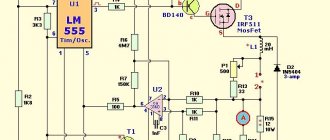
A circuit using a forward-biased diode as a sensor is described in the article “Differential temperature sensor for controlling a PC fan.”
Semiconductor diode on reverse (thermal) current
The property of changing the thermal current depending on the junction temperature. This dependence approaches:
It ~ |U|1/2
As well as the resistance of the reverse branch, which is also proportional to |U|1/2.
The reverse (thermal) current of the diode, which is most interesting for us, also depends on temperature. Its approximate dependence on temperature has the form:
I0(t) ≈ I0(t0)eαΔt
where: αSi = 0.13 ºC-1, αGe = 0.09 ºC-1.
The reverse current doubles for:
- silicon diode, with a temperature change of 10 ° C,
- germanium diode, with a temperature change of 14 °C.
Dignity:
— High sensitivity allows you to create simple and sensitive temperature sensors based on this inclusion.
Flaws:
— The thermal current temperature sensor has a large dynamic range of current changes. This requires the use of special matching circuits when measuring large temperature differences.
— Strong dependence of the thermal current on the bias voltage.
The listed disadvantages require individual configuration of circuits with a temperature sensor on a thermal current, which means a sufficiently highly qualified experimenter. But it also gives him the opportunity to very flexibly choose the operating point of the temperature sensor.
A circuit using a thermal current diode as a sensor is described in the article “Regulating the rotation speed of a case fan for a personal computer system unit.”
Thermocouple
Thermocouple (thermoelectric temperature transducer) is a thermoelement used in measuring and converting devices of various automation and control systems and devices. It consists of two wires made of different metals (having different thermopower coefficients), soldered at one point. Different metals have different thermopower coefficients (which, by the way, depends on temperature) and, accordingly, the potential difference that arises between the ends of different conductors will be different and dependent on temperature.
TPs are used to measure the temperature of various types of objects and environments, as well as in automated control and monitoring systems.
Advantages of thermocouples:
- Large temperature measurement range: from -200 °C to 2200 °C
- High accuracy when using calibration curves (determined by the accuracy of their reading) - realistically 0.1°C, possibly higher
- Simplicity
- Cheapness
- Reliability
Flaws:
- Accuracy worse than 1 °C is difficult to achieve* in universal multimeters,
- The readings are affected by the riser temperature, which must be corrected for.
- An error arises from changes in the temperature of the cold junction
- Peltier effect (at the time of taking readings, it is necessary to exclude the flow of current through the thermocouple, since the current flowing through it cools the hot junction and warms up the cold one)
- nonlinear dependence of thermoEMF on temperature
Requirements for thermocouples are determined by GOST 6616-94.
Types of thermocouples.
- platinum-rhodium - platinum - TPP13 - Type R
- platinum-rhodium - platinum - TPP10 - Type S
- platinumrhodium-platinumrhodium-TPR – Type B
- iron-constantan (iron-copper-nickel) TLC - Type J
- copper-constantan (copper-copper-nickel) TMKn - Type T, SS
- nikrosil-nisil (nickel-chromium-nickel-silicon) TNN - Type N.
- chromel-alumel - THA - Type K
- chromel-constantan THCn - Type E
- chromel-copel - THC - Type L
- copper - copel - TMK - Type M
- sil-silin - TSS - Type I
- Tungsten-rhenium - tungsten-rhenium - TVR - Type A-1, A-2, A-3
Industrial thermocouples have a long (>30 s) time constant. Because it is necessary to warm up not only the thermocouple, but also its protective shell.
*A few words should be said about the accuracy of thermocouples.
There is an opinion that thermocouples have low measurement accuracy. It is realistic to have a thermocouple measurement accuracy (one thermocouple without a converter) close to 0.1 °C at positive temperatures up to 100 °C. This is achieved by using a calibration table (graph) when directly measuring the potential difference with a millivoltmeter with a high accuracy class.
Accuracy class 1 thermocouple gives according to GOST 8.401-80 gives a thermocouple measurement error of the order of ± 1 ° C in the range of measured temperatures, usually equal to.
A thermocouple is a finished product, often enclosed in a protective shell that protects it from mechanical influences. But, it is made of special wire. These are two wires made of a pair of metals with different thermopower coefficients (for example, chromel - copel), each of which is enclosed in its own insulating shell (for high temperatures it is an asbestos thread with fixing impregnation) and has a similar general insulation. This is a thermocouple wire. Such a wire, once supplied as an independent product on the basis of which industrial thermocouples are made, can be used for the manufacture of thermocouples without a protective sheath with a speed of much less than 1 second (the thinner the wire, the higher the speed).
I used this wire and thermocouples made from it. Such a thermocouple has a small time constant, and when using calibration tables, the measurement accuracy can exceed 0.1 °C in the temperature range 20 -:- 95 °C.
Brief conclusions and recommendations by Victor Garcia (“Temperature measurement: theory and practice”
) on the use of thermocouples.
The quality of a thermocouple temperature measurement system can be improved in the following ways:
- Use the thickest possible conductors that do not remove heat from the measured area (but I would recommend using thinner conductors, taking into account point 2).
- If it is necessary to use thin conductors, try to reduce their length as much as possible.
- If possible, protect the sensor and wires from shock and vibration, which can degrade system performance.
- Do not expose the thermocouple to sudden temperature fluctuations and use it and connecting wires only within the operating temperature range.
- If possible, keep a record of the measurement results.
Microchip-based temperature sensors
Temperature sensors are a microcircuit in a 3-pin plastic or metal case.
Analog temperature sensors K1019EM and TMP35, 36,37 and DS60.
Various temperature sensors from domestic and foreign manufacturers have been developed and used. They can have analog and digital output. Analog sensors are described in "".
As is already clear, the sensors have an analog voltage output.
Accuracy of analog sensors ± 0.5 -:- 1 °C.
Digital temperature sensors type DS18S20.
The sensor has a digital output with a 1-Wire® interface.
With the help of additional calculations, the discreteness of the temperature representation can be reduced; in our case, it is equal to 0.1°C. The most attractive thing is that such a thermometer is already calibrated at the factory, the guaranteed accuracy is ±0.5°C in the range of –10..+85°C and ±2°C over the entire operating temperature range.
Other digital sensors DS1620, DS1621, DS1624, DS1629, DS1821.
The main disadvantage of such sensors is their large size and, as a result, greater inertia.
Temperature meters
All of the sensors listed above can be used separately, although this requires appropriate measuring instruments (such as a thermocouple - galvanometer, millivoltmeter) or matching devices (for example, when using resistance thermometers). Or as part of complete temperature meters.
Most portable temperature meters use thermocouples as sensors. They have a measurement accuracy of 0.1 - 1 °C.
In stationary thermal control systems, semiconductor thermistors are used, and in cases where more precise control is required, resistance thermistors are used.
Direct current diodes as temperature sensors are widely used in microelectronics as part of processor chips and other microcircuits requiring temperature control. Diodes are made in a single technological process during the manufacture of the chip itself and cost practically nothing. True, there is a need for a separate contact pin on the contact panel of the processor or other chip. In some types of processors, a conversion circuit is also built into the chip; this unit is used to automatically control the performance of the processor and protect it from overheating.
Non-contact temperature meters include meters that measure radiant IR energy emanating from heated bodies, in the range of 8-14 microns.
Non-contact temperature meters allow you to study surface temperatures and are used for preventive maintenance, detection of mechanical and electrical defects before an accident, for energy audits and monitoring of technological processes, in medical and veterinary research.
Pyrometers
A pyrometer is a measuring device for non-contact temperature measurement and is based on the use of infrared radiation from controlled objects.
The operating principle of an infrared pyrometer is based on measuring the absolute value of the emitted energy of one wave in the infrared spectrum. This is a relatively inexpensive non-contact method of temperature measurement. These devices can be aimed at an object from any distance and are limited only by the diameter of the spot being measured and the transparency of the environment. They are ideal for portable models and therefore can operate on a point and measure basis.
Infrared thermometers, often called pyrometers, use the principle of an infrared radiation detector. The intensity and spectrum of radiation depends on body temperature. By measuring the radiation characteristics of a body, the pyrometer indirectly determines the temperature of its surface.
Purpose of pyrometers
- measuring the temperature of remote and hard-to-reach objects;
- temperature measurement of moving parts;
- inspection of parts exposed to life-threatening voltage;
- control of high temperature processes;
- recording rapidly changing temperatures;
- inspection of parts or surfaces that are not accessible for measurement;
- examination of materials with low thermal conductivity or heat capacity.
Areas of application of pyrometers
- thermal power engineering;
- electric power industry;
- metallurgy and metalworking;
- electronics - temperature control of elements and parts;
- diagnostics of internal combustion engines;
- electric motors and bearings;
- temperature control of production processes;
- control of storage and transportation conditions of food products;
- inspection of buildings and structures;
- transport - diagnostics of road and rail transport;
- heating, ventilation and air conditioning systems;
- inspection of refrigeration equipment.
Pyrometer performance
Since pyrometers are used in cases of rapid temperature changes, speed is an important characteristic for them. It is usually estimated by the time to reach 95% of the steady-state reading (reading settling time) and is 0.5 - 1 second.
Optical resolution
The sensitivity area of a pyrometer can be approximately represented by a cone, the top of which rests on the instrument lens, and the base is located on the surface of the object. The ratio of the height of the cone to its diameter L:D, called the optical resolution of the pyrometer, is one of the main characteristics of the device (sometimes the inverse value is used - D:L). The larger the L:D, the smaller the objects the pyrometer can distinguish at a distance.
The sensitivity area of the pyrometer can be considered conical only at a sufficient distance. Up close it has a more complex shape. Often, the sensitivity zone of a pyrometer first narrows to a minimum, and then begins to expand in the shape of a cone. The distance F at which the minimum diameter of the sensitivity zone d is achieved is called the focal length. For such pyrometers, parameters F and d are indicated in the documentation. There are special short-focus pyrometers with d of 5...8 mm at a distance F of 300...600 mm.
Advantages:
Possibility of contactless temperature measurement.
Flaws:
To ensure the specified measurement accuracy, it is necessary to set correction factors for different radiating surfaces. This is setting the emissivity of the controlled surface according to the tables.
Without introducing emissivity, you can get an error of several degrees (according to the manufacturer) and more than 30 °C on the surface of metals, especially with high-quality surface treatment.
Pyrometers measure the average surface temperature within a sensitivity range.
The high price of pyrometers with emissivity correction and high optical resolution, which are necessary for monitoring the temperature of electronic components. (>$500)
Thermal imagers
Thermal imager
— a device for monitoring the temperature distribution of the surface under study. The temperature distribution is displayed on the display (and in the memory) of the thermal imager as a color field, where a certain color corresponds to a certain temperature. The display (of many models) shows the temperature range of the surface visible through the lens. The typical resolution of modern thermal imagers is 0.1°C.
A thermal imager is an expensive device. Its main elements - the matrix and lens - make up about 90% of the total cost. The matrices are very difficult to produce, but over time, according to experts, their price may decrease. The situation with lenses is more complicated: they cannot be made of glass, because this material does not transmit IR radiation. For this reason, rare and expensive materials (for example, germanium or special glass) are used to create lenses.
Advantages:
- Can show a visual image, which helps in comparing temperatures over a large area
- Allows you to find emergency elements before they fail
- Measurement in areas where other methods are impossible or dangerous
- Unbrakable control
Flaws:
- High price, but high-quality cameras are very expensive,
- Thermal imaging images are often difficult to understand even for professionals. Images require complex analysis, using visible light shooting of the object in question,
- Most cameras have an accuracy of ±2% or less
- Ability to measure surface temperatures only
Practice shows that, apart from specialized ones, there are no temperature sensors that operate on the “set it and forget it” principle. Only complete temperature meters can be classified in this category.
Unfortunately, temperature sensors based on semiconductor diodes are not available. Standard diodes are poorly adapted to this, since they have housings with low thermal conductivity and their dimensions are much larger than the diode itself. They can be used mainly as temperature sensors for the medium in which they are placed (air, liquid).
As temperature sensors, at a point on the surface of the controlled object, they are not structurally adapted.
Almost all sensors used to measure temperatures require some training for the person using them. First of all, because their use requires their control or calibration at least in 1 - 2 points, and if an accuracy of more than 1% is required, full calibration is required.
If an industrially manufactured temperature measuring device is not annually certified by Rosstandart, it is required to be periodically checked on its own at at least two points. At zero (0°C) and 100°C.
My experience shows that the use of thermocouples when debugging (contact measurements with a large number of controlled points) of PC cooling systems is optimal. You can even record the temperature distribution over the surface.
— They have maximum speed (1-10 sec.).
— They allow you to perform measurements by direct contact at a given point on the controlled surface. All this makes it possible to control many points in a fairly short time.
— When using calibration tables (curves), their accuracy can exceed all means used for measuring temperatures.
MAIN!
The use of temperature sensors in protective shells for PC measurements can only be recommended at permanent monitoring points!
They not only have a measurement time of 30-60 seconds, due to their large mass (the measurement can be considered completed only when the meter readings are set to a static state), but also lower the real temperature due to heat removal from their large surface (due to its large area).
For such sensors, their use can be recommended in accordance with the article “Measuring the temperature of AMD processors” by Sergey Veremeenko, only the temperature sensor must be glued with heat-conducting glue.
Direct diode connection
The pn junction of the diode can be affected by voltage supplied from external sources. Indicators such as magnitude and polarity will affect its behavior and the electrical current conducted through it.
Below we consider in detail the option in which the positive pole is connected to the p-type region, and the negative pole to the n-type region. In this case, direct switching will occur:
- Under the influence of voltage from an external source, an electric field will be formed in the pn junction, and its direction will be opposite to the internal diffusion field.
- The field voltage will decrease significantly, which will cause a sharp narrowing of the blocking layer.
- Under the influence of these processes, a significant number of electrons will be able to freely move from the p-region to the n-region, as well as in the opposite direction.
- The drift current indicators during this process remain the same, since they directly depend only on the number of minority charged carriers located in the pn junction region.
- Electrons have an increased level of diffusion, which leads to the injection of minority carriers. In other words, in the n-region there will be an increase in the number of holes, and in the p-region an increased concentration of electrons will be recorded.
- The lack of equilibrium and an increased number of minority carriers causes them to go deep into the semiconductor and mix with its structure, which ultimately leads to the destruction of its electrical neutrality properties.
- In this case, the semiconductor
Diode reverse current
pulsed reverse current of the diode - Irev.i, IRM The largest instantaneous value of the reverse current of the diode caused by the pulsed reverse voltage. [GOST 25529 82] Topics: semiconductor devices EN peak reverse current DE Spitzensperrstrom der Diode FR courant inverse de crête ... Technical Translator's Guide
Pulse reverse current of the diode - 11. Pulse reverse current of the diode D. Spitzensperrstrom der Diode E. Peak reverse current F. Courant inverse de crête Irev.i The largest instantaneous value of the reverse current of the diode caused by the pulse reverse voltage Source: GOST 25529... ... Dictionary-reference book terms of normative and technical documentation
constant reverse current of the diode - Iobr, IR [GOST 25529 82] Topics semiconductor devices EN reverse continuous current DE Sperrgleichstrom der Diode FR courant inverse continu... Technical Translator's Guide
Constant reverse current of the diode - 10. Constant reverse current of the diode D. Sperrgleichstrom der Diode E. Reverse continuous current F. Courant inverse continu Irev Source: GOST 25529 82: Semiconductor diodes. Terms, definitions and letter designations of parameters... Dictionary-reference book of terms of normative and technical documentation
reverse current of a semiconductor diode reverse current of a semiconductor diode vok. Rückwärtsstrom bei einer Halbleiterdiode, m rus. reverse current of a semiconductor diode, m pranc. courant inverse d … Automatikos terminų žodynas
repeating pulsed reverse current of the rectifier diode - Shobr.ip IRRM The value of the reverse current of the rectifier diode caused by the repeating pulsed reverse voltage. [GOST 25529 82] Topics: semiconductor devices General terms rectifier diodes EN repetitive peak reverse... ... Technical Translator's Guide
Diode reverse connection
Now we will consider another method of switching on, during which the polarity of the external source from which the voltage is transmitted changes:
- The main difference from direct connection is that the created electric field will have a direction that completely coincides with the direction of the internal diffusion field. Accordingly, the barrier layer will no longer narrow, but, on the contrary, expand.
- The field located in the pn junction will have an accelerating effect on a number of minority charge carriers, for this reason, the drift current indicators will remain unchanged. It will determine the parameters of the resulting current that passes through the pn junction.
- As the reverse voltage , the electric current flowing through the junction will tend to reach its maximum. It has a special name - saturation current.
- In accordance with the exponential law , with a gradual increase in temperature, the saturation current indicators will also increase.
Methods for determining polarity
To determine the polarity of a diode product, you can use various techniques, each of which is suitable for certain situations and will be considered separately. These methods are divided into the following groups:
- A visual inspection method that allows you to determine the polarity based on existing markings or characteristic features;
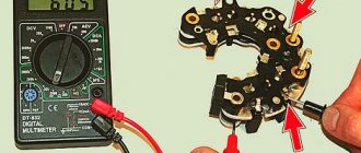
- Checking with a multimeter turned on in dialing mode;
- Finding out where is the plus and where is the minus by assembling a simple circuit with a miniature light bulb.
Forward and reverse voltage
The voltage that affects the diode is divided according to two criteria:
- Direct voltage is the one at which the diode opens and direct current begins to flow through it, while the resistance of the device is extremely low.
- Reverse voltage is one that has reverse polarity and ensures that the diode closes with reverse current passing through it. At the same time, the resistance indicators of the device begin to increase sharply and significantly.
The pn junction resistance is a constantly changing indicator, primarily influenced by the forward voltage applied directly to the diode. If the voltage increases, then the junction resistance will decrease proportionally.
This leads to an increase in the parameters of the forward current passing through the diode. When this device is closed, virtually the entire voltage is applied to it, for this reason the reverse current passing through the diode is insignificant, and the transition resistance reaches peak parameters.
Current detection
There are several methods to accomplish this. Let's consider the simplest of them. To determine the current rating of an LED, you will need a tester called a multimeter. This method is also used for conventional diodes.
LED current measurement
Testing is carried out as follows:
- The multimeter probes are connected with the positive terminal to the anode, and the negative terminal to the cathode.
- The anode lead of the LED is made longer than the cathode lead.
- You can ring LEDs that have a low supply voltage. If they have high power, this method cannot be used.
It is better to use a proven method of measuring device characteristics. For this you will need:
- power supply rated for 12 V;
- multi-amperemeter;
- fixed resistors - 2.2 and 1 kOhm, as well as 560 Ohm;
- variable resistor – 470–680 Ohm;
- voltmeter, preferably digital;
- wires for switching the circuit.
As in the previous case, you will need to find out the polarity of the diode. If it is not clear from its terminals where “+” and “-” are, then you will have to connect a 2.2 kOhm resistor to one of the terminals. After this, you need to connect the LED to the power supply. When it lights up, you need to turn off the power and mark the desired output “+”.
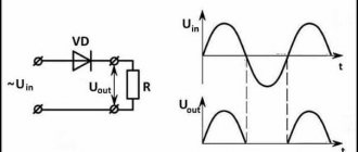
Diode operation and its current-voltage characteristics
The current-voltage characteristic of these devices is understood as a curved line that shows the dependence of the electric current flowing through the pn junction on the volume and polarity of the voltage acting on it.
Such a graph can be described as follows:
- The axis is located vertically: the upper area corresponds to the forward current values, the lower area to the reverse current parameters.
- Horizontal axis: The area on the right is for forward voltage values; area on the left for reverse voltage parameters.
- The direct branch of the current-voltage characteristic reflects the passing electric current through the diode. It is directed upward and runs in close proximity to the vertical axis, since it represents the increase in forward electric current that occurs when the corresponding voltage increases.
- The second (reverse) branch corresponds to and displays the state of the closed electric current, which also passes through the device. Its position is such that it runs virtually parallel to the horizontal axis. The steeper this branch approaches the vertical, the higher the rectifying capabilities of a particular diode.
- According to the graph, it can be observed that after an increase in the forward voltage flowing through the pn junction, a slow increase in the electric current occurs. However, gradually, the curve reaches an area in which a jump is noticeable, after which an accelerated increase in its indicators occurs. This is due to the diode opening and conducting current at forward voltage. For devices made of germanium, this occurs at a voltage of 0.1V to 0.2V (maximum value 1V), and for silicon elements a higher value is required from 0.5V to 0.6V (maximum value 1.5V).
- The indicated increase in current readings can lead to overheating of semiconductor molecules. If the heat removal that occurs due to natural processes and the operation of radiators is less than the level of its release, then the structure of the molecules can be destroyed, and this process will be irreversible. For this reason, it is necessary to limit the forward current parameters to prevent overheating of the semiconductor material. To do this, special resistors are added to the circuit, connected in series with the diodes.
- By examining the reverse branch, you can notice that if the reverse voltage applied to the pn junction begins to increase, then the increase in current parameters is virtually unnoticeable. However, in cases where the voltage reaches parameters exceeding the permissible norms, a sudden jump in the reverse current may occur, which will overheat the semiconductor and contribute to the subsequent breakdown of the pn junction.
How to determine the current of an electric motor if the power is known?
How to find the rated current of a motor
Knowing the rated power, it will not be difficult to calculate the values of the electric motor currents. Let's say we don't know the rated current of a 45 kW motor - how, in this case, can we determine the motor current by power? When connected to a three-phase 380 Volt network, the current is determined using the exact calculation formula:
In = 45000/√3(380*0.92*0.85) = 45000/514.696 = 87.43A
- In - current strength of the asynchronous motor
- Pn - rated engine power 45 kilowatts
- √3 — square root of three = 1.73205080757
- Un — mains voltage 380V
- η - efficiency 92% (in calculations 0.92)
- cosφ - power factor 0.85
How to determine the rated current of an electric motor if the power factor and efficiency are unknown? In this situation, we can find the rated current of the motor with a small error using the ratio - two amperes per kilowatt. Determine the electric motor current using the formula:
How to determine the starting current of a motor
Starting currents of electric motors can be found and calculated using the formula:
Iп is the current value when starting an asynchronous motor, which needs to be found out
In - already calculated rated current
K - multiplicity of motor starting current (find in the passport)
Basic diode faults
Sometimes devices of this type fail, this may occur due to natural depreciation and aging of these elements or for other reasons.
In total, there are 3 main types of common faults:
- Breakdown of the junction leads to the fact that the diode, instead of a semiconductor device, becomes essentially a very ordinary conductor. In this state, it loses its basic properties and begins to pass electric current in absolutely any direction. Such a breakdown is easily detected using a standard multimeter, which starts beeping and shows a low resistance level in the diode.
- When a break occurs, the reverse process occurs - the device generally stops passing electric current in any direction, that is, it essentially becomes an insulator. To accurately determine a break, it is necessary to use testers with high-quality and serviceable probes, otherwise they can sometimes falsely diagnose this malfunction. In alloy semiconductor varieties, such a breakdown is extremely rare.
- Leakage , during which the tightness of the device body is broken, as a result of which it cannot function properly.
Breakdown of pn junction
Such breakdowns occur in situations where the reverse electric current begins to suddenly and sharply increase, this happens due to the fact that the voltage of the corresponding type reaches unacceptable high values.
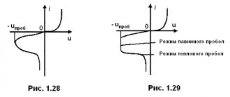
There are usually several types:
- Thermal breakdowns , which are caused by a sharp increase in temperature and subsequent overheating.
- Electrical breakdowns that occur under the influence of current on a junction.
The graph of the current-voltage characteristic allows you to visually study these processes and the difference between them.
Electrical breakdown
The consequences caused by electrical breakdowns are not irreversible, since they do not destroy the crystal itself. Therefore, with a gradual decrease in voltage, it is possible to restore all the properties and operating parameters of the diode.
At the same time, breakdowns of this type are divided into two types:
- Tunneling breakdowns occur when high voltage passes through narrow junctions, which allows individual electrons to escape through it. They usually occur if semiconductor molecules contain a large number of different impurities. During such a breakdown, the reverse current begins to increase sharply and rapidly, and the corresponding voltage is at a low level.
- Avalanche types of breakdowns are possible due to the influence of strong fields that can accelerate charge carriers to the maximum level, due to which they knock out a number of valence electrons from atoms, which then fly into the conductive region. This phenomenon is avalanche-like in nature, which is why this type of breakdown received its name.
Thermal breakdown
The occurrence of such a breakdown can occur for two main reasons: insufficient heat removal and overheating of the pn junction, which occurs due to the flow of electric current through it at too high rates.
An increase in temperature in the transition and neighboring areas causes the following consequences:
- The growth of vibrations of the atoms that make up the crystal.
- entering the conductive band.
- A sharp increase in temperature.
- Destruction and deformation of the crystal structure.
- Complete failure and breakdown of the entire radio component.
How to check a diode?
To determine the health of the diode, you can use the following method for checking it with a digital multimeter.
But first, let's remember what a semiconductor diode is.
A semiconductor diode is an electronic device that has the property of unidirectional conductivity.
The diode has two terminals. One is called the cathode, which is negative. The other output is the anode. It is positive.
At the physical level, the diode is a single pn junction.
Let me remind you that semiconductor devices can have several pn junctions. For example, the dinistor has three of them! A semiconductor diode is essentially the simplest electronic device based on just one pn junction.
Let us remember that the operating properties of the diode appear only when connected directly. What does direct connection mean? This means that a positive voltage (+) is applied to the anode terminal, and a negative voltage is applied to the cathode, i.e. ( — ). current begins to flow through its pn junction .
When turned on in reverse, when a negative voltage ( - ) is applied to the anode and a positive voltage (+) is applied to the cathode, the diode is closed and does not allow current to pass through .
This will continue until the voltage on the reverse-connected diode reaches a critical value, after which damage to the semiconductor crystal occurs. This is the main property of the diode - one-way conductivity.
The vast majority of modern digital multimeters (testers) have the ability to test a diode in their functionality. This function can also be used to test bipolar transistors. It is indicated in the form of a diode symbol next to the marking of the multimeter mode switch.
A little note! It is worth understanding that when checking diodes in direct connection, the display does not show the transition resistance, as many people think, but its threshold voltage ! It is also called the voltage drop across the pn junction . This is the voltage above which the pn junction opens completely and begins to pass current. If we draw an analogy, this is the amount of effort aimed at opening the “door” for electrons. This voltage ranges from 100 to 1000 millivolts (mV). This is what the device display shows.