Voltmeter, what is it? First of all, this is a device that serves as a measuring device for voltage values up to 1000V in DC and AC networks, industrial frequency and is used in information measuring systems. An ideal voltmeter has an extremely high, infinite resistance; due to the high resistance of the device, the highest accuracy and wide range of uses are achieved.
The device is designed to provide mathematical and logical processing of measurements.
Types of voltmeters
There are two types of voltmeters:
- Portable or portable voltmeters designed to check (test) the voltage in the network. As a rule, such a device is included in the design of the tester; a distinction is made between digital or dial instruments; in addition to measuring voltage, they perform the function of measuring load currents, circuit resistance, temperature, etc. If digital instruments are distinguished by the accuracy of their readings, then the types of voltmeters related to analog ( pointer) devices, are able to respond to the slightest deviations of parameters that are not determined by a digital device.
- Stationary devices are installed on instrument panels in electrical distribution panels to monitor the operation of equipment; these devices belong to the electromagnetic type.
Security measures
Unlike other devices, such as an ohmmeter or a megometer, when working with a voltmeter, you have to deal with voltage. At small values it does not pose a danger to humans. Great care must be taken when measuring voltages that can create a dangerous current flowing through the human body.
Voltage measurements must be accompanied by full compliance with safety regulations and operating regulations. This will prevent electrical injury. It is prohibited to work without protective equipment, such as rubber gloves and mats. Upon completion of the work, there should be no exposed live parts that could cause accidental contact by maintenance personnel.
The widespread use of voltage measurement in electrical engineering has led to the creation of voltmeters of various designs. They differ both in operating principle and in accuracy. The most popular are universal devices that can automatically select not only the limit, but also the type of controlled value.
If you have any questions, leave them in the comments below the article. We or our visitors will be happy to answer them
Voltmeter Specifications
Normal operation of the voltmeter is possible at an air temperature not exceeding 25 - 30 o C with a relative air humidity of up to 80% at an atmospheric pressure of 630 - 800 mm Hg. Art. Mains frequency 50 Hz and voltage 220V (frequency up to 400 Hz). The measurement is greatly influenced by the shape of the AC supply voltage curve - a sinusoid with a harmonic coefficient of no more than 5%.
The capabilities of the device are assessed using the following indicators:
- Device resistance.
- Range of measured voltage values.
- Measurement accuracy class.
- Frequency limits for alternating circuit voltage.
Main technical parameters
The main technical characteristics of the voltmeter, included in the user manual and the device passport, in accordance with international standards:
- internal resistance of the voltmeter;
- measurement range within which the specified accuracy is ensured when the device is correctly connected;
- when working with alternating voltage, the operating frequency is indicated.
One of the most important parameters is the accuracy class. It is always displayed on the instrument scale. With its help, you can determine the error with which the result is obtained after connecting the device to the network.
Operating principle of the device
The voltmeter is based on the method of analog-to-digital conversion with push-pull integration. Let's consider the operation of the device using the example of V7-35. Converters installed in the structure, measuring DC and AC voltage values, current strength, resistance, are converted into a normalized voltage and, when using an ADC, converted into a digital code.
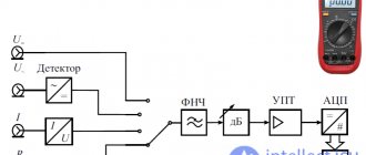
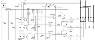
The functional diagram of a digital voltmeter works using 4 converters:
- Scaling converter.
- A low-frequency device that converts alternating current voltage into direct current.
- Converter of DC and AC power into voltage.
- Resistance to voltage converter.
Rice. No. 2. Digital voltmeter circuit
Connecting the device
Voltage control always occurs in parallel. The measurement can be carried out at both the power source and the load. The voltmeter connection diagram is shown in the figure below.
Device connection diagram
Subtleties that must be taken into account before connecting the voltmeter:
- A correctly selected measurement range will protect the device and the circuit under test from damage. Particular care should be taken when the voltmeter reading is close to the limit. A jump in EMF can burn the windings of the measuring device;
- A pointer voltmeter can provide standard accuracy only if positioned correctly. If the device indicates horizontal placement, then placing it vertically is prohibited, and vice versa. You should also pay attention to the absence of vibrations and strong magnetic fields;
- Measurements with a voltmeter can be performed both under voltage and by disconnecting the circuit from the power source and then turning it on;
- When working with dangerous voltage levels, it is recommended to use protective gloves and dielectric mats;
- When using an analog device, before starting measurements, you must check that the arrow points exactly to zero. If necessary, adjust using a special adjusting screw;
- If necessary, calibration is carried out;
- To ensure high accuracy of measurements, you should check how long ago the voltmeter was verified.
Often devices have several measurement limits. Analog voltmeters use different connection diagrams for each value. In digital ones, it is enough to place the pointer opposite the required value. The most modern devices are able to automatically determine the measurement limit and change it during voltage monitoring.
AC voltmeter
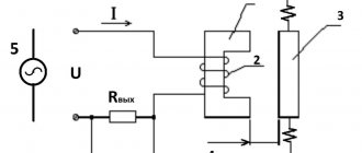
Broadband electronic voltmeters used in alternating current networks have their own design features and graduations unique to them. The degree of influence on the measured circuit during the study depends on the complex input parameters, these are: input active resistance (Rv), while the resistance should be the highest, input capacitance (Cv), it should be as small as possible and inductance (Lpr), it together with the capacitance, it creates a series oscillatory circuit, distinguished by its resonant frequency.
Rice. No. 3. Connection diagram for a high-frequency voltmeter.
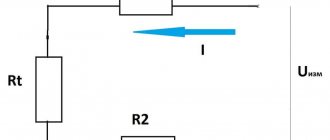
Measuring resistance with a voltmeter
A low-resistance voltmeter with a resistance of no more than 15 ohms is suitable for measuring resistance and is performed using the formula:
Rx = Ri * (U1/U2 – 1)
The formula uses the resistance of the voltmeter Rv, as well as 1 and 2 readings of the voltmeter; the accuracy of the measurement does not always correspond to reality, since the measurement is carried out without taking into account the internal resistance of the device. A more accurate result is achieved when using the formula :
Rx = (Rв + r) * (U1/U2 - 1), internal resistance - r.
When measuring, each subsequent resistance should be greater than the resistance of the voltmeter and will be carried out with each measurement recorded.
In order to determine what voltage the voltmeter shows, they are guided by the voltmeter scale, using the device’s division value. It is determined by the upper limit of the measured value, which is divided by the number of scale divisions.
Recently, an acquaintance heard the word “voltmeter” in some casual conversation and asked what it was. So, let's refresh our school knowledge.
EMF and voltage, or what a voltmeter measures
Nowadays, in our home, at work and on the street, everything depends on electricity. We constantly use electric current - alternating and direct. Current is the directed movement of charge carriers under the influence of an electric field. So, voltage, or potential difference, is a physical quantity equal to the work an electric field does when transferring a unit charge from one place to another.
Read also: Do-it-yourself sprayer from a vacuum cleaner
When we talk about a galvanic cell, where internal chemical processes occur, or a turbine, which is rotated by the waters of a river, it is incorrect to use the expression “potential difference”, because the work of moving a charge is carried out by external forces of a chemical or mechanical nature. For such cases, the concept of electromotive force (EMF) is used. It is this indicator that is written on batteries that are sold at the checkout in a store, and when we connect a voltmeter to the terminals without connecting a circuit with a load, we will see exactly it.
Both EMF and voltage are measured in volts. Formally, the dimension of this unit is explained as follows: the potential difference between points A and B is equal to 1 V, if to move a charge of 1 coulomb from point A to point B we spend 1 joule of work. From this unit - volt - comes the everyday name for voltage when it is measured: voltage.
The principle of operation of a voltmeter
Its work is based on the principle of Ohm's law.
Ohm's law states: "The voltage across a resistance is directly proportional to the current passing through it."
Any basic meter has a potential difference across its terminals when full-scale current flows through it.
The symbol for a voltmeter is a circle with a V inside.
The voltmeter is always connected in parallel to the load in the circuit for which the voltage is to be measured.
A DC voltmeter has polarity signs. Therefore, it is necessary to connect the plus (+) terminal of the voltmeter to the upper potential point and the minus (-) terminal to the lower potential point to obtain the deviation of the voltmeter.
The AC voltmeter has no polarity marks and can be connected either way.
However, in this case also the voltmeter is still connected in parallel to the load for which the voltage is measured.
A high voltage range voltmeter is created by connecting a resistance in series with a measuring mechanism that has a full voltage scale as shown in the figure below.
Full voltage scale
How does a voltmeter work?
If we need to measure voltage, then we need to make sure that no current passes through the measuring device. Therefore, we connect the device in parallel to the operating circuit. The circuit continues to operate, and the meter must have a very high series resistance in order for its readings to be as accurate as possible. In its simplest form, the device consists of a magnetic system in which there is a movable frame-coil. Spiral springs are attached to this frame, which create a counteracting moment and arrow.
Such simple magnetoelectric devices were usually seen by everyone in childhood. By the way, the device for measuring current - an ammeter - is designed in the same way, only the load in it is small and is placed in parallel, and the device itself is placed in the circuit in series.
There are also electromagnetic devices (where a fixed coil and a moving core interact) and electrodynamic devices (where two coils work).
In addition to these three types, voltmeters with other circuit diagrams are also used, but they have narrower areas of application. Such devices include thermoelectric (they use the property of current to heat a conductor) and rectifier (which combines a diode rectifier and a magneto-electric mechanism).
All these devices have one thing in common - a scale on which we see the measurement results. The larger the parameter being measured, the more the needle deviates. Devices of this kind are called analog. Their disadvantage is obvious: with prolonged use, the mechanism tends to wear out, readings often depend on environmental conditions, and it is more convenient to perceive information from the screen, where the numbers we need are shown. And here digital voltmeters come to our aid.
Principle of displaying measurement results
A feature of digital measuring instruments is that the analog signal (if you display it on a graph, you get a straight line at constant voltage, and a sine wave at alternating voltage) is converted into a digital signal, after which it goes to the counter and screen, where we see the measurement result. This scheme is implemented using microcircuits, the range of which currently allows the production of a wide variety of devices - for example, for measuring the amplitude of alternating voltage, pulse, phase-sensitive
Classification
With all their diversity, these measuring instruments can be classified according to several parameters. This will help you choose the one you need if you are planning to purchase it.
So, voltmeters can be classified according to:
- operating principle;
- scope of application;
- designs;
- accuracy class.
According to the principle of operation, voltmeters are electromechanical and electronic. The first include simple devices described in the previous chapter - magnetoelectric, electrodynamic, electromagnetic, thermoelectric, rectifier and electrostatic. The second includes devices with digital and analog signal conversion and output to the panel.
According to the scope of their application, devices are manufactured for measuring direct current, alternating current, universal, pulse, phase-sensitive and selective.
By design, they can be portable, which are devices with “crocodile clips” (they can be put in a bag, or even in a pocket) and stationary, which are used indoors. The latter also include panel panels: they are designed for permanent installation in the dashboard.
The accuracy class on measuring instruments is marked with a number, and not everyone pays attention to this, but in vain. Sometimes the accuracy of the device is of fundamental importance.
The number not circled shows the relative measurement error, and it is given as a percentage. In Russia there are the following classes of instrument accuracy by relative error: 6, 4, 2.5, 1.5, 1.0, 0.5, 0.2, 0.1, 0.05, 0.02, 0.01 , 0.005, 0.002, 0.001. The indicated figure shows by how many percent the instrument readings may differ from the true value of the measured value. It is important that this is relevant within the operating range of the device, and this range must be indicated on the device. It does not always coincide with the zero mark of the scale: for values close to zero, the probability of error tends to infinity.
If the device has an uneven scale, then the accuracy class is indicated by a number under which the angle sign appears. This means that the error is given in fractions of the scale length.
Read also: Drilling machine quill drawing
The fraction designation shows the error at the end of the scale and at the beginning.
The difference between digital instruments is that the measured range in them is adjustable; this allows for more accurate measurements.
Classification and principle of operation
Classification
- According to the principle of operation, voltmeters are divided into: electromechanical - magnetoelectric, electromagnetic, electrodynamic, electrostatic, rectifier, thermoelectric;
- electronic - analog and digital
- direct current;
- panel;
Analog electromechanical voltmeters
- Magnetoelectric, electromagnetic, electrodynamic and electrostatic voltmeters are measuring mechanisms of the corresponding types with indicating devices. To increase the measurement limit, additional resistances are used. The technical characteristics of an analog voltmeter are largely determined by the sensitivity of the magnetoelectric measuring device. The lower its total deflection current, the higher the high-resistance additional resistors can be used. This means that the input resistance of the voltmeter will be higher. However, even when using a microammeter with a total deviation current of 50 μA (typical values 50..200 μA), the input resistance of the voltmeter is only 20 kOhm/V (20 kOhm at the measurement limit of 1 V, 200 kOhm at the 10 V limit). This leads to large measurement errors in high-resistance circuits (the results are underestimated), for example, when measuring voltages at the terminals of transistors and microcircuits, and low-power high-voltage sources.
- EXAMPLES:
M4265, M42305, E4204, E4205, D151, D5055, S502, S700M
- A rectifier voltmeter is a combination of a DC current sensing meter (usually magnetoelectric) and a rectifier device. EXAMPLES:
Ts215, Ts1611, Ts4204, Ts4281
- EXAMPLES:
T16, T218
Analog electronic voltmeters for general purposes
Analog electronic voltmeters contain, in addition to a magnetoelectric measuring device and additional resistances, a measuring amplifier (direct or alternating current), which makes it possible to have lower measurement limits (up to tens - units of millivolts and below), significantly increase the input resistance of the device, and obtain a linear scale at small within the measurement limits of alternating voltage.
Field surveying is different and eliminates misconceptions about field lines such as concentric circular circles. Rice. 5: Demonstration of slow rotating three-phase current field. Since this method has little practical use in primary schools, we would like to develop a dedicated resource for this demonstration and offer it to one of the teaching aid manufacturers. We think elementary school physics teachers who are more than just happy with chalk and blackboard will be happy.
If the circuit voltage is unknown, set the range to the highest voltage value and set the dial to ṽ. Most multimeters turn on in auto-correction mode. This automatically selects the measuring range depending on the voltage present. When finished, remove the wires in reverse order: red first, then black. Connect the test leads to the circuit: black lead first, red lead second.
General purpose digital electronic voltmeters
The operating principle of discrete voltmeters is to convert the measured constant or slowly varying voltage into an electrical code using an analog-to-digital converter, which is displayed digitally on a display.
Note: AC voltage has no polarity. Caution: Do not allow your fingers to touch the lead tips. Don't let the tips touch each other. Read the measurement on the display. When finished, remove the red wire first, the black wire second.
Other Useful Features for AC Voltage Measurement
It can be viewed after the measurement is completed. Click on the corresponding button to set the multimeter to a specific reference value. Measurements are displayed above and below the reference value. Avoid this common and serious mistake: insert test leads into the wrong input jacks. This could result in a dangerous arc flash.
Diode-compensation AC voltmeters
The principle of operation of diode-compensation voltmeters is to compare, using a vacuum diode, the peak value of the measured voltage with a reference DC voltage from the voltmeter's internal adjustable source. The advantage of this method is a very wide operating frequency range (from a few hertz to hundreds of megahertz), with very good measurement accuracy; the disadvantage is the high criticality of the deviation of the signal shape from a sinusoid.
- EXAMPLES:
V3-49, V3-63 (using a 20 mm probe)
Currently, new types of voltmeters have been developed, such as V7-83 (20 mm probe) and VK3-78 (12 mm probe), with characteristics similar to diode compensation ones. The latter may soon be approved for use as working standards. Among foreign analogues, we can highlight voltmeters of the URV series from Rohde & Schwarz with probes with a diameter of 9 mm.
Pulse voltmeters
1. Pulse voltmeters are designed to measure the amplitudes of periodic pulse signals with high duty cycle and the amplitudes of single pulses.
Phase sensitive voltmeters
Phase-sensitive voltmeters (vector meters) are used to measure the quadrature components of the complex voltages of the first harmonic. They are equipped with two indicators for reading the real and imaginary components of the complex voltage. Thus, a phase-sensitive voltmeter makes it possible to determine the complex voltage, as well as its components, taking the initial phase of a certain reference voltage as zero. Phase-sensitive voltmeters are very convenient for studying the amplitude-phase characteristics of four-terminal devices, such as amplifiers.
Selective voltmeters
A selective voltmeter is capable of identifying individual harmonic components of a signal of complex shape and determining the root-mean-square value of their voltage. In design and principle of operation, this voltmeter is similar to a superheterodyne radio receiver without an AGC system, which uses an electronic DC voltmeter as its low-frequency circuits. Complete with measuring antennas, a selective voltmeter can be used as a measuring receiver.
- EXAMPLES:
B6-4, B6-6, B6-9, B6-10, SMV 8.5, SMV 11, UNIPAN 233 (237), Selective nanovol
Voltmeter selection
If you decide to buy yourself a voltmeter, you need to decide on the following:
- In what ranges will measurements be made? Agree, there is a big difference between working at a step-down substation, where the range is from 10 kV to 380 V, and repairing household appliances, where this range is from 3 V to 220 V.
- Under what conditions will the device be used? Will it be a home, laboratory, street or you need to move around clients.
- Is there a need to measure other parameters? Usually it is always there, the only question is whether to buy separate devices or one multimeter.
If you work with high voltages, you are better off choosing electromechanical kilovoltmeter manufacturers. They have a sufficient accuracy class for large quantities, and at the same time they have one undoubted advantage - reliability. Electronic devices powered by microelectronics still have a problem with this: they react poorly to overloads and break down. The market offers both portable and panel-mounted versions of such devices.
Stationary devices are preferable for work in a laboratory or workshop. They are represented by a fairly large assortment - both electromechanical and digital.
Some people living in the private sector need a voltmeter to install it in the panel (usually it is on a pole near the house). Panelboard voltmeters are designed for this, which can be installed in a DIN rail - just like meters and RCDs are installed, for example. They cost from 900 to 4000 rubles, and are most often produced in a digital version, but if the voltage in your area has a habit of “jumping”, then you can also purchase an electromechanical one - by the way, they are cheaper.
Finally, if you take measurements on the road, a voltmeter is not enough for you. Since the 90s of the last century, testers, or multimeters, have become popular among those whose work involves moving. They existed before, but their accuracy left much to be desired. Now the choice and quality of these devices have increased significantly, and their price is relatively low. What advantages do testers have?
- Measurement of several parameters. At a minimum, testers measure voltage, current and resistance, and more versatile models include functions such as checking transistors, measuring temperature and measuring continuity for cable breaks.
- Compactness. Looks like a smartphone.
- Possibility to select the measurement range.
- Convenient probes. Some models are also equipped with “crocodile clips”.
Both digital and analog testers are produced. The latter are more reliable, but less accurate: from time to time you have to put the arrow back in place.
How to use
How is the voltmeter connected? Parallel! This rule should have been learned in school.
Make sure the measurement range matches the expected circuit voltage. If this range is large (kilovolts), accuracy will suffer; if it is small, the device will suffer.
If the voltmeter is electromechanical, install it correctly. The manufacturer indicates how to do this. The accuracy of the readings depends on this.
If the voltmeter is designed to measure DC voltage, do not try to use it to measure AC voltage. If it is universal, then switch it to the desired mode.
A voltmeter with an arrow needs to be adjusted to the “0” position. This is done with a screwdriver if there is no special handle.
Do not grab the exposed parts of the probes with your bare hands, especially if the voltage in the network is more than 60 V. At a minimum, this is unpleasant, at a maximum - you understand. Work with high voltages with gloves.
Features of the use of voltmeters in various cases
To get an accurate voltage reading, you need to turn on the measuring device correctly. The connection must only be parallel. It is important to observe polarity. It can be determined by the diagram, which indicates how to correctly connect the measuring instruments. Theoretically, an ideal voltmeter will be as accurate as possible when the internal resistance is very high. In this case, a minimum current will pass through it.
In a real situation, this condition is not met, so the measurement is made taking into account the expected voltage value. In this case, you need to set the voltmeter switch in accordance with the desired range.
The choice of a voltmeter for measuring DC voltage depends on the value of the latter:
- If the voltage does not exceed 1 millivolt, then use devices with a built-in amplifier.
- Up to 1000 volts, conventional measuring instruments of various types can be used.
- If you need to check this parameter in a high-voltage area, then it is necessary to use special electrostatic devices designed to operate in electrical networks with voltages above 1000 V.
With your own hands
Despite the fact that the choice of voltmeters is now huge, there are always people who always want to do everything themselves. There are different opinions about what this is connected with. I will not comment on anyone’s wishes, this is not the topic of the article. But I’ll tell you how to make a voltmeter with your own hands (or remake an old one). After all, nothing is impossible here.
Electromechanical voltmeter
You will need the following components:
- magnetic head with an arrow from an old broken device;
- scale;
- a piece of paper and glue;
- resistors 1.5 kOhm, 19.5 kOhm, 199.5 kOhm and 1999.5 kOhm;
- 4 diodes. When choosing them, be sure to look at their characteristics - they must withstand the circuit parameters that you plan to measure;
- Copper wire;
- Soldering iron, solder, rosin;
- Calibration tester;
- Batteries, electrical appliances and everything where you can measure voltage in a very different range;
- Switch.
The first diagram shows a simple DC voltmeter with four measurement ranges - the choice of range depends on what load we place the switch on. In the additional circuits we see diode bridges: their installation expands the use of the device; now they can measure voltage in an alternating current network.
Read also: Equipment for cold stamping of sheet metal
Before assembly, make sure that the magnetic head with the arrow is in good condition, its spiral springs are not torn off and the frame moves normally. After this, you can begin installing the bridge, and then connect the resistor magazine with the switch. You will also need to make a new scale. To do this, cover the old paper with paper, cut along the contour and draw 4 semicircular lines on it. After assembly, you can begin calibration. To do this, you need to measure the voltage with a tester, and then, switching the new product to the required range, with our new device. Make a mark on the scale. And so on until the scale is graduated.
Warning: Wear gloves before testing high voltages.
If desired, you can also make a digital voltmeter. There are plenty of circuits for this on the Internet, as well as components. I will present one of the circuits, on an 8-bit microcontroller, here. Designed to measure voltages up to 30 V
In general, if your hands are not for boredom, go for it!
A voltmeter is a device that is used to measure voltages up to 1000 V in DC and AC networks of industrial frequency and is used in information measurement systems. A quality voltmeter has an extremely high, infinite resistance. Thanks to the high resistance of the device, optimal measurement accuracy is achieved.
The device is designed for logical and mathematical processing of measurements.
Names and designations
Species names
- Nanovoltmeter
- a voltmeter with the ability to measure very low voltages (less than 1 µV) - Microvoltmeter
- a voltmeter with the ability to measure very low voltages (less than 1mV) - Millivoltmeter
- a voltmeter for measuring small voltages (units - hundreds of millivolts) - Kilovoltmeter
- voltmeter for measuring high voltages (more than 1 kV) - Vectormeter
- phase sensitive voltmeter
Designations
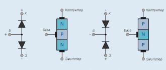
- Electrical voltmeters are designated depending on their operating principle D
xx - electrodynamic voltmeters - M
xx - magnetoelectric voltmeters - C
xx - electrostatic voltmeters - T
xx - thermoelectric voltmeters - Ф
xx,
Ш
xx - electronic voltmeters - Ts
xx - rectifier type voltmeters - E
xx - electromagnetic voltmeters
- B2-
xx - DC voltmeters
xx - AC voltmeters
xx - pulse current voltmeters
xx - phase-sensitive voltmeters
xx - selective voltmeters
xx - universal voltmeters
In order to understand the meaning of this question, let's carefully look at the sinusoidal voltage graph in Fig. 4.2. At each moment of time, the voltage in it is different - accordingly, the value of the current through the load resistor to which we apply such a voltage will also be different. At the moments of time designated 772 and T (that is, multiples of half the period of our oscillation), the voltage on the load will generally be equal to zero (no current flows through the resistor), and in the intervals between them it changes up to a certain maximum value equal to the amplitude value of A. In the same way, the current through the load will change, and therefore the power released (which does not depend on the direction of the current - physicists will say that power is a scalar quantity, not a vector one). But the process of heat release is extremely inertial - even such a small object as the hair of an incandescent light bulb does not have time to noticeably cool down in 1/100 of a second, which passes between voltage peaks in an industrial network with a frequency of 50 Hz. Therefore, we are most often interested in the average power over a long period of time. What will it be equal to?
To accurately answer this question, you need to take integrals: the average power over a period is the time integral of the square of the voltage function. Here we will present only the result: the amount of average power in an alternating current circuit is determined by the so-called. effective value of voltage (В), which for a sinusoidal oscillation is related to its amplitude value (f/a) by the following formula: Exactly the same formula is valid for current. When they say “alternating voltage 220 V,” they always mean the effective value. In this case, the amplitude value is approximately 311 V, which is easy to calculate if you multiply 220 by the root of 2. This value should always be kept in mind when choosing components for operation in AC networks - if you take a diode rated for 250 V, then it can easily fail when operating in a normal network, in which the instantaneous value exceeds 300 V, although the effective value is equal to 220 V. But for components that use the heating effect (light bulbs, resistors, etc.), when calculating the permissible power, you need to have it seems to be the actual value.
It is incorrect to call the effective value “average”; it is correct to call it root mean square (according to the calculation method - through the square of a function of time). But there are also concepts of average value, and not just one, but even two. Simply “average” (strictly in the meaning of the name) is the sum of all instantaneous values for the period. Since the lower part of the sinusoid (under the x-axis) is strictly symmetrical relative to the upper, you don’t even need to take integrals to realize that the average value of the sinusoidal voltage shown in Fig. 4.2, is exactly equal to zero - the positive part compensates for the negative. But such a value is not very informative, so the average-rectified (average-amplitude) value is more often used, in which the signs are not taken into account (that is, the absolute value of the voltage is substituted into the integral). This value (U is related to the amplitude value (U according to the formula is equal to approximately 1.57-f/c-
Rice. 4.5. Graphs of some non-sinusoidal oscillations
For constant voltage and current, the effective, average and average amplitude values coincide and are simply equal to the voltage (current) value. However, in practice, variable oscillations are often encountered, the shape of which differs from both a constant value and a strictly sinusoidal one. Oscillograms of some of them are shown in Fig. 4.5. For such signals, the above relationships for effective and average values are not valid! The simplest case is shown in Fig. 4.5, b-oscillation is a sinusoid, but shifted upward by the amplitude. Such a signal can be represented as the sum of a constant voltage of magnitude A (constant component) and an alternating sinusoidal voltage (variable component). Accordingly, its average value will be equal to A, and the current A-^aHi. For a rectangular oscillation (Fig. 4.5, b) with equal duration positive and negative half-waves (sym-
metric meander) the relationships are very simple: effective value = average amplitude = amplitude, as for direct current, but the average value is equal to zero, as for sine. In a case that is often encountered in practice, when the minimum of the rectangular voltage coincides with zero, that is, the voltage fluctuates from zero to the supply voltage (not shown in Fig. 4.5), such a meander can be considered similarly to the case in Fig. 4.5, V, as the sum of constant voltage and rectangular. For the uppermost case (Fig. 4.5, a), which is a sinusoidal voltage passed through a full-wave rectifier (see chapter P), the effective and average amplitude values will be equal to the corresponding values for a sinusoid, but the average will not be equal to zero, but the same with medium amplitude. For the lowest case (Fig. 4.5, d) it is generally not easy to indicate all these quantities, since they depend on the shape of the signal.
But even after learning all this, you still won’t be able to measure non-sinusoidal voltages and currents with a multimeter! Do not forget about this, as well as the fact that for each multimeter there are limiting values of the oscillation frequency - if you connect the multimeter to a circuit with other parameters, it can show anything - “the weather on Mars”, in a common expression. Measuring instruments for alternating voltage are calibrated in effective voltage values, but they, as a rule, measure average amplitude (at least the majority - we will not dwell on the details now), and figuring out exactly how to recalculate the readings is not always easy. And for complex signals, as in Fig. 4.5, d, this results in a real puzzle at the level of tasks for students of mechanical and mathematics. An oscilloscope and knowledge of the relationships given earlier for signals of the most common form can help out, but for more complex ones we don’t need to calculate the effective and average values.
Notes in the margins
The only device that will correctly display the value of the effective voltage of any form is an analog voltmeter of the electromagnetic system (they can be easily recognized by an uneven scale, the divisions on which are further and further apart towards the end). In order to measure non-sinusoidal voltage with a digital instrument, an integrating filter (low-pass filter), described in Chapter 5, can be inserted between the measured value and the voltmeter.
For rectangular stresses representing a meander similar to Fig. 4.5, b, there is one more important characteristic. After all, no one forbids imagining a rectangular voltage in which the valleys are shorter or longer than the spikes. In electronics, a meander, without further explanation, means a symmetrical form of a rectangular voltage, in which the valleys are strictly equal in duration to the bursts, but, generally speaking, this is not necessary. In Fig. Figure 4.6 shows two examples of such stresses in comparison with a symmetrical meander. The characteristic of the relationship between the durations of parts of a period is called duty cycle and is defined as the ratio of the duration of the entire period to the duration of the positive part (this is exactly the case, and not vice versa, that is, the duty cycle value is always greater than I). For a meander, the duty cycle is 2, for narrow short pulses it will be more than 2, for wide pulses it will be less.
Types of voltmeters
There are two types of voltmeters:
If digital instruments are characterized by accuracy of readings, then analog (arrow) voltmeters can respond to minimal deviations of parameters that are not determined by a digital tester.
- Portable (or portable) voltmeters are designed to check (test) the voltage in the network. In most cases, this device is included in the tester design. There are pointer or digital instruments; in addition to measuring voltage, they measure load currents, temperatures, circuit resistance, etc.
- Stationary voltmeters are installed on the dashboard in electrical distribution panels. They are designed to monitor the operation of equipment. Stationary voltmeters are of the electromagnetic type.
Classification
The devices differ in their operating principle; they can be electronic or electromechanical.
According to their intended purpose, the devices are pulsed, measuring AC and DC networks.
Voltmeter Specifications
The voltmeter can function normally at air temperatures not exceeding 25–30 ºС and relative humidity up to 80% at an atmospheric pressure of 630–800 mm Hg. Voltage 220 V (frequency up to 400 Hz), mains frequency 50 Hz. The measurement is significantly influenced by the shape of the supply voltage curve - a sinusoid with a harmonic coefficient of max 5%.
The capabilities of the device are assessed using the following indicators:
- Resistance.
- AC voltage limits.
- Range of measured voltage values.
- Measurement accuracy class.
Operating principle of the device
The basis of the voltmeter's operation is the analog-to-digital conversion method. Thus, the converters installed in the design of the B7-35 device measure the magnitude of AC and DC voltage (as well as resistance, current), converting the measured value into a normalized voltage, and then using an ADC into a digital code.
The functional diagram of the digital tester works using 4 converters:
- Scaling converter.
- Converter of AC and DC power into voltage.
- A low-frequency device that converts AC voltage to DC.
- Resistance to voltage converter.
Rice. No. 2. Digital voltmeter circuit
Description of some types of measuring devices
The V3-57 microvoltmeter is capable of operating with alternating voltage from 5 Hertz to 5 MHz. The result is displayed by calculating the root mean square value. The device is capable of working with voltages of any shape. The resistance of the voltmeter is at least 5 MOhm. The device is most widely used in radio engineering for setting up equipment.
Appearance of microvoltmeter V3-57
AKIP-2401 AC voltage meters have two channels. It is also possible to fix the result on the screen using the “Hold” button. The device has an RS-232 interface that allows you to read data remotely.
Digital voltmeter AKIP-2401
The V7-40/1 device is primarily used for high-precision scientific research and verification of other voltmeters. Its resistance reaches 2 GOi with a measurement limit of 2 V. This makes it possible to minimize the influence on the circuit, which is important when working with low-voltage radio circuits. B7-40/1 is successfully used in automation equipment and SCADA systems.
High-precision, discrete voltmeter V7-40/1
AC voltmeter
Electronic broadband voltmeters, which are used in alternating current networks, have design features and graduations unique to them. The impact on the measured circuit depends on the input parameters: input active resistance (Rv) (it should be the highest), input capacitance (Cv) (it should be minimal) and inductance (Lpr) (together with the capacitance a series oscillatory circuit is created , which differs in its resonant frequency).
Rice. No. 3. Voltmeter connection diagram
Resistance measurement
A low-resistance voltmeter with a resistance of max 15 ohms is suitable for measuring resistance, which is performed using the formula:
Rx = Ri * (U1/U2 – 1).
The formula uses the resistance Rv (voltmeter), and 1 and 2 readings of the device, the accuracy of the measurement does not necessarily correspond to reality, because the measurement does not take into account the internal resistance. A more accurate result can be achieved by using the formula:
Rx = (Rв + r) * (U1/U2 - 1), where r is the internal resistance.
When measuring, each subsequent resistance should be large and be carried out with a record of each measurement.
To find out what voltage the device shows, you need to be guided by the voltmeter scale and the division value. It is determined by the maximum limit of the measured value, divided by the number of scale divisions.
Rules for connecting a voltmeter
Before you begin to determine the voltage in the electrical network, you should make the right choice of the type of voltmeter, taking into account the features of using various models. It is also necessary to take into account a number of parameters:
- Internal resistance of the measuring device. The higher it is, the more accurate the measurement result. The circuit of the voltmeter used will help determine this characteristic. In practice, it is important that its operating range be greater than the value of the measured parameter. The device must be marked accordingly.
- Voltage range to be measured. Typically, the voltmeter is connected after selecting the required option. Measurement of very small or large voltages is carried out using special devices - amplifiers or transformers.
- If you need to know the magnitude of the alternating voltage, it is necessary to take into account not only the potential difference, but also the operating frequency. Each voltmeter is turned on subject to certain permissible limits within which it must be used.
- An important characteristic is the measurement error. It is almost impossible to achieve ideal measurement accuracy by connecting the device. Therefore, the master must know exactly the maximum permissible error. It is usually indicated on the device.
Important! To determine the voltage, connect a voltmeter to the circuit in parallel, otherwise you will only be able to determine the source emf, if any.