Phase is plus or minus
In the process of carrying out apartment renovations or repairing home electrical equipment, many, usually unexperienced amateur electricians, have questions about what color of wire
needs to be connected to a particular cable core,
where is the phase and where is the zero
in the socket, and others. All these questions are very correct and necessary, because not only the safety of the electrician and the people around him, but also the uninterrupted operation of the electrical network in the house or apartment depends on the correct answer to them. Color marking of each core in a modern cable is not a whim or an advertising “trick” of manufacturers. On the contrary, this is a strict standard that is followed all over the world, determined by safety regulations, and also significantly simplifies the installation procedure and speed.
Color marking of conductors
GOST R 50462-2009 establishes rules for color marking of conductor insulation to improve safety and simplify work with electrical installations.
Electrical installation rules (PUE) require easy recognition of the type of conductor by the color of its insulation.
Mandatory colors are established for the neutral conductor and for protective grounding. The insulating coating of the neutral is always done using blue or light blue polymers.
The insulation of the ground wire is painted with alternating stripes of yellow and green. If the conductor is combined and is intended to simultaneously connect the neutral and protective grounding, its insulation is painted green, blue and yellow.
It is customary to use brown, black and gray as the color of insulation of phase conductors. Brown insulation is most often found in two- or three-core electrical cables. Black and gray colors are used in cables intended for building three-phase networks.
However, the choice of colors for phase conductors is not a GOST requirement, but a recommendation.
There may be electrical cables on sale, the insulation of the phase conductors of which can be made in a variety of colors, for example, in red, white or any other except blue and green with yellow (painting only green or only yellow is allowed, if the possibility of erroneous conductor identification).
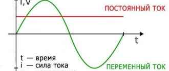
In industry, in addition to AC networks, DC networks are widely used. For the positive conductor of such a network, it is prescribed to use insulation painted red, and for the negative conductor - blue.
You should know that the old Soviet wiring, which is still found at various facilities, had a different color marking:
- phases were marked with yellow, green (sometimes neon) and red colors;
- neutral was marked in bluish or gray color.
Characteristics of the plus and minus wires
If an electrical cable has 2 conductors, then one of them is “plus” (phase), and the second is “minus” (zero). It is imperative to know the polarity when connecting an electrical appliance, otherwise there is a risk of damage to the equipment.
Important! Most often, “plus” and “minus” are marked with letters, symbols or a specific color provided by GOST.
In electrical circuit diagrams, the phase (“plus”) is marked with the Latin letter L; the same marking is used on wires if there is no color difference. The Latin letter N means “zero” or “minus”. Grounding is marked as PE or PEN.
Sometimes, when working with wiring that does not have any identification marks, they use markers that are placed on the wires in the form of colored rings with marks. Another marking option could be shrink tape of different colors. It is put on a cable of the appropriate voltage and, to secure it to the carrier, is heated.
PHASE, ZERO, GROUNDING
Let's first figure out what a phase is and what a zero is, and then we'll see how to find them.
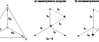
On an industrial scale, we produce three-phase alternating current, but in everyday life we use, as a rule, single-phase. This is achieved by connecting our wiring to one of the three phase wires (Figure 1), and for further consideration of the material, which phase comes into the apartment is completely indifferent to us. Since this example is very schematic, we should briefly consider the physical meaning of such a connection (Figure 2).
Electric current occurs in the presence of a closed electrical circuit, which consists of the winding (Lt) of the substation transformer (1), the connecting line (2), and the electrical wiring of our apartment (3). (Here the designation of phase is L, zero - N).
Another point - in order for current to flow through this circuit, at least one electricity consumer Rн must be turned on in the apartment. Otherwise, there will be no current, but the VOLTAGE on the phase will remain.
One of the ends of the Lt winding at the substation is grounded, that is, it has electrical contact with the ground (Zml). The wire that comes from this point is neutral, the other is phase.
This leads to another obvious practical conclusion: the voltage between “zero” and “ground” will be close to zero (determined by grounding resistance), and “ground” will be “phase”, in our case 220 Volts.
In addition, if hypothetically (In practice this cannot be done!) we ground the neutral wire in the apartment by disconnecting it from the substation (Fig. 3), the voltage “phase” - “zero” will be the same 220 Volts.
We figured out what phase and zero are. Let's talk about grounding. I think its physical meaning is already clear, so I propose to look at it from a practical point of view.
If, for some reason, electrical contact occurs between the phase and the conductive (metal, for example) body of an electrical device, voltage appears on the latter.
When you touch this body, an electric current may flow through the body. This is due to the presence of electrical contact between the body and the “ground” (Fig. 4). The lower the resistance of this contact (wet or metal floor, direct contact of the building structure with natural grounding conductors (heating radiators, metal water pipes), the greater the danger you face.
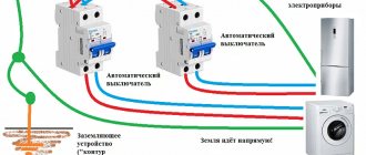
The solution to this problem is to ground the housing (Figure 5), in which case the dangerous current will “disappear” through the grounding circuit.
Structurally, the implementation of this method of protection against electric shock for apartments and office premises consists of laying a separate PE grounding conductor (Fig. 6), which is subsequently grounded in one way or another.
How this is done is a topic for another discussion; for example, in a private house you can make a grounding loop yourself. There are various options with their own advantages and disadvantages, but for further understanding of this material they are not fundamental, since I propose to consider several purely practical issues.
What happens in zero and phase when a wire breaks
If the electrical wire is broken, the corresponding outlet or the device connected to it ceases to function. It does not matter whether the phase or neutral wire is damaged. If the cable between the switchboards of an apartment building and one of its entrances breaks, all apartments connected to the entrance switchboard will lose electricity. If one of the phase wires breaks in a three-phase connection, the current that was in it before appears in the neutral wire, while nothing changes in the two remaining phases.
GOST rules for marking wires
GOST R 50462-2009 provides for both letter and color marking of wires and contacts. One does not exclude the other.
The requirements of this regulatory document apply to electrical networks being created and repaired. There is no need to alter existing properly functioning wiring to bring it into compliance with GOST requirements.
If it is not possible to use conductors with the correct color of insulation, they can be marked on both ends of the conductor using heat shrink, insulating tape or press-on pin sleeve insulated lugs (NSVI).
Advantages and disadvantages of car cigarette lighters
The most important advantage of a cigarette lighter is the ability to connect a huge number of electrical appliances to it, making life easier on the road. However, due to switching such large amounts of current, the design of this device is unreliable. In addition, we must not overlook the fact that every time we connect gadgets to the cigarette lighter, we create a mechanical load on its elements. Ideally, car manufacturers would consider increasing the strength by adding more presser feet. Then the plug would stay in the cigarette lighter more “confidently”.
Wire colors in electrical wiring
Battery polarity
The color identification scheme is convenient not only for installation. As a rule, different contractors install and operate electrical wiring. Compliance with standards prevents errors during repair work and in the modernization process.
Something to remember! Domestic standards have changed several times over the past decades. Currently, the markings discussed above are used.
Color of zero working and zero protective wires
The color options for the shells will help you recognize the intended purpose of the conductors:
- blue – working zero;
- transverse or longitudinal combinations of yellow and green stripes - protective zero;
- main blue with a change to a combination of yellow and green stripes at the junctions - combined working and protective zero.
For your information. The last universal option can be done in the reverse way. The main part of the line is created from a combination of yellow and green stripes, with blue color applied at the junctions.