Advantages and disadvantages of various implementations of the Star-Delta circuit
Before talking about the advantages of the FiF engine start relay, I will tell you about the disadvantages of other implementations of the circuit.
Nobody in new equipment implements the “Star-Triangle” circuit on a time relay, because this circuit has several disadvantages:
- Pneumatic and mechanical relays are capricious;
- For normal operation of the circuit, a second relay is needed, which must implement a pause between modes, but it is usually not installed;
- Using a universal electronic relay is identical in cost to using a specialized one, but what’s the point then?
The control circuit on the controller must contain the controller itself, which also performs other functions in the equipment. But the controller is not always present. And if there is one, then the price of the equipment and the requirements for its functionality require the installation of a frequency converter. And then the requirements for smooth engine acceleration naturally disappear.
So, in the absence of a controller, specialized Star-Delta relays are used, which fully implement the required engine starting algorithm, while having all the necessary adjustments on the front panel.
Weekly timer
An electronic on-off timer in automatic mode is used in various fields. The “weekly” relay switches within a predetermined weekly cycle. The device allows:
The dimensions of the device are small , and the design includes function keys. Using them, you can easily program the device. In addition, there is a liquid crystal display that displays information.
The front of the panel assumes the presence of one or more potentiometer rods. They can be adjusted using a screwdriver blade and set to the desired position. There is a marked scale around the stem. Such devices are widely used in control structures of ventilation and heating systems.
Expert opinion
It-Technology, Electrical power and electronics specialist
Ask questions to the “Specialist for modernization of energy generation systems”
Time relay - device and principle of operation. Do-it-yourself connection diagrams and settings However, almost all mechanisms of this type have a separation of switching contacts and timer power circuits. Ask, I'm in touch!
Design and appearance of the engine start relay
The FiF PCG-417 time relay for controlling electric motors according to the “Star-Triangle” scheme looked like this on the store window a minute before I bought it:
F&F relay on a store window
Nearby were his brothers in the brand, which is represented very widely in Taganrog - more than 25 items.
Why I bought it that day will be discussed below, but for now let’s take a closer look at this device. If you need official instructions, you can download them below.
The appearance is at the beginning of the article, here are a few more photos.
Time relay F&F PCG-417. View from above
In this photo there is an emphasis on the upper terminals, this is where the power is connected:
Star-delta relay FiF - view of the power terminals
As always, FiF uses a universal housing, and the discrepancy between terminal numbers and actual terminal locations is a little confusing.
The bottom terminals are actually the switching contacts of the output relays:
Time relay output terminals FiF
The relay has a standard housing size of 1S, which means that it takes up exactly the same amount of space on the DIN rail as a single-pole circuit breaker:
DIN rail mounting
Digital relays
The first digital relays, which appeared in the second half of the last century, were based on pulse generators, counters and logic elements.
Time relays built according to such schemes are precise devices with stepwise adjustment of the response time. The clock frequency generator of the device, which is stabilized by a quartz resonator, is built on the basis of the K176IE12 microcircuit. K176IE12 counters generate temporary pulses, which, through logical elements 4I-NOT, generate a control voltage for the relay Rel1, the switching connection of devices. Switches SA1, SA2 adjust the response time.
Technical characteristics of the Star-Delta relay
The parameters can be viewed in the table:
Relay parameters F&F PCG-417
There is no point in discussing much; I will only note a few points.
The relay has two supply voltages (220 and 24 V), which is very convenient in real life - based on this voltage, you can select the voltage of the contactor coils. Or vice versa - having specific contactors for 24 V (AC/DC) or 220 V (AC), you can connect the required power to the relay.
The maximum current of the relay output contacts is 8 A, but for a real load (contactor coils) that is reactive in nature, the output current should be limited to 2 A. For particularly powerful contactors, intermediate relays will have to be used. Another note. The instructions state that “The product must be used for its intended purpose.” However, in the same instructions energy-saving and fluorescent lamps are considered as loads for this relay...
The acceleration time in the “Star” circuit can be adjusted smoothly from 1 s to 1000 s (16 minutes), and the pause (switching) time changes in steps, depending on the acceleration time. More details below.
I would like to draw the attention of meticulous readers like me – what are “sec” and “ms”? If these are units of time, then such units are not in the list of SI units. I consider this a drawback for serious technical documentation.
How to read labels
Relay marking using the example of CHINT Electric NJS3 series
When choosing a marking code, manufacturers tried to simplify its perception as much as possible. Only the most necessary data is indicated on the relay body:
- company manufacturer;
- device model;
- rated voltage (usually 220 Volts).
When marking, the type of current on which a given brand of device operates is sometimes indicated: direct or alternating.
Data on the maximum permissible current load may be provided on the housing. For most time relay samples, the input and output contacts are also marked on it with separate designations of “zero” and “phase”. Among the well-known manufacturers of these products, Russian ones stand out, as well as Rele-Avtomatika and Novatek-Electro.
Control Panel
The relay control panel displays the main indicators and controls:
Star-Delta relay control panel
Power Indicator – Illuminates green when power is supplied. At the same time, according to the operating algorithm, the general contactor and the “Star” contactor or the “Triangle” contactor must be turned on (except for the pause time);
The mode switching indicator - when working in the "Star" mode - blinks red, when working in the "Triangle" mode - it lights up evenly.
The acceleration time selection switch (turning on the “Star” circuit) together with the multiplier potentiometer provides the choice of any time. For example, to select a time of 30 s, you need to set the switch to “10” and the multiplier to “3”. Some time settings can be selected through 2 or 3 different knob positions. For example, for 100s there are 3 combinations: 10s x 10, 50s x 2, 100s x 1.
The left and right side of the controller have the same acceleration time (1, 5, 10, 50, 100s), but different pause times between modes (75ms and 150ms). I recommend choosing a longer time to ensure the greatest stability of the circuit. A shorter time can be selected when contactors of the 1st and 2nd magnitude are used in the circuit (motor power less than 4 kW).
Operation timing diagram
We are slowly getting to the point. Now the algorithm of operation of the device will be described in detail.
Timing diagram based on previous article:
Diagram of operation of the Star-Delta relay
What has changed compared to the time relay circuit? Added a pause between “Star” and “Triangle”, 75 or 150 ms.
The same diagram in the instructions for the relay:
Operation diagram from the instructions for the Star-Delta relay
The diagrams show conditionally the power supply and the activation of internal relays (Star and Triangle outputs). Relays have two discrete states - “on” and “off”. It is strange that in the third graph, during the pause, the “Triangle” relay is turned on “a little bit”. What could this mean?
The same diagram is shown on the side of the device:
Relay side with diagram and circuit
The triangle relay also turns on “slightly” during the pause, and the pause itself is indicated by an unknown unit of measurement “msek”. I wonder what universities the designer who wrote this studied at? I consider this unprofessional.
So, according to the diagram, when power is applied to the relay (U), the common contactor KM1 and the “Star” contactor KM2 (inverted “Y”) are started simultaneously.
This lasts for a time set by the user. Next, after this time has elapsed, the KM2 contactor turns off and a pause of 75 or 150 ms occurs, the duration of which can also be selected. During a pause, voltage is supplied to the motor through the common contactor KM1, but no current flows, because the chain is broken. Due to the inertia of the engine, the pause does not have any effect on the rotation speed.
After the end of the pause, the KM3 contactor is turned on, and the engine is switched to “Triangle”, easily reaching the nominal mode.
Operating principle
The relay is triggered by a physical or mechanical influence: the appearance of a control electric current, an increase or decrease in local illumination, the formation or change of a local magnetic field, thermal energy, sound pressure, etc.
Time relays are also used: they operate after a specified time interval or at a designated moment (if the control signal has not appeared earlier). Such models are installed to turn on or start certain mechanisms or processes, turn them off or regulate them.
In everyday life, such devices are used almost everywhere: a timer for a washing machine or heating system, a microwave oven or electric oven, a street traffic light or lighting. Such relays are already built into the design of the product and are most often designed for repair or replacement. Due to the complexity and uniqueness of most timer designs, it is recommended to contact service repair shops.
However, you can replace, repair and install it back, or simply install a new timer yourself. They are installed in a limited range of devices (heating, ventilation and heating devices, as well as some individual mechanisms), so their principle of operation is known and can be regulated.
Connection diagram for time relay Star Triangle Euroautomatika F&F PCG-417
Let's now critically examine the diagram given in the manufacturer's instructions. First, the internal diagram of the engine control relay:
Relay contacts
Connection diagram:
Relay connection diagram from the instructions
Unfortunately, the power part and the control part are intertwined in the diagram, which makes it difficult to read. Let's figure it out.
The diagram shows the power supply of the relay 230 V, from one of the phases. The relay and motor are started by applying power via an unmarked NO contact. This could be a toggle switch, a relay, or a controller output. Power is supplied to the relay (input 3) and to the power supply of the contactor coil SG (G - General, general, my designation - KM1).
At the same time, contacts 7 and 9 are closed, including the contactor SY (KM2), including the motor according to the “Star” circuit. After acceleration, contacts 7 and 9 open, and the motor rotates for 75 or 150 ms without power.
After the switching time, the “Triangle” contactor SΔ (KM3) is turned on, starting the engine in operating mode.
The disadvantage of this scheme, as I said in the previous article, is the lack of interlocks, which are needed to prevent emergency situations. The fact is that I have repeatedly come across faults in which contactors or relays are stuck. This was either due to a mechanical reason (jamming) or due to burnt contacts.
In the above diagram there are no interlocks for the contactor circuits. I am sure that there are no blockings inside the FiF PCG-417 relay, since two ordinary independent relays are used, each having one switching contact. Apparently, the manufacturer simplified the circuit for the sake of reliability. Below is an example in which there are locks.
The contactors in the circuit are 230 V, but you can also use 380 V by connecting the common wire of the contactors not to N, but to phase L2 or L3.
Step-by-step installation instructions
Before you try to independently connect a time relay to the controlled circuit, you will need to decide on the type of power supply - single-phase or three-phase. It is also necessary to know what load the device will switch and for what time intervals it should be designed. Based on these data, a relay with characteristics suitable for the stated purposes is purchased. Further steps to install it are as follows:
- By means of the input circuit breaker, the electrical network into which the time relay is planned to be connected is de-energized.
- The product is fixed on a DIN rail in the cabinet next to the electric meter.
- On the relay body there are input and output contacts, marked according to generally accepted markings.
- The phase and zero coming from the meter are connected to the input terminals, and the conductors going towards the RCD or machine are connected to the output terminals.
Experts advise testing it for functionality before turning off the power and installing the device in a cabinet. To do this, you need to connect a regular cord with a plug to the input terminals and plug it into the network. Having set any time period on the device, you should wait until the relay operates and the output voltage disappears. To monitor the output state, you will need a measuring device (tester or multimeter). If they are not there, you should connect a regular light bulb to the output and by the disappearance of its glow, judge the functionality of the relay. No special device configuration required
When connecting conductors to contact terminals, it is important to ensure that the bolts are properly tightened. To eliminate possible problems during operation of the device, it must be as reliable as possible.
Example of installation in a steam boiler
So why did I go to the store to buy this relay?
Now there will be a terrible story. The fact is that at our enterprise in the boiler room there is an Italian steam boiler (steam generator), which provides steam for the technological process and for heating.
I upgraded this boiler, about which there was already an article on the blog Using a soft starter.
One Saturday in March, the engineer on duty called me and said that we had an emergency - the fan motor on the boiler did not turn on. More precisely, it launches into “Star”, but does not go to “Triangle”. Accordingly, the air pressure in the burner does not reach the required value, and the boiler “goes into error.”
Here's the engine:
Motor with star-delta connection circuit
Engine nameplate that switches from Star to Delta
Connecting the motor in a boron box:
Connecting the motor in the terminal box
The culprit of the emergency situation, when the premises were left without heating and the enterprise without production, turned out to be a time relay for starting the Siemens Sirius 3RP1574 engine. This relay worked for more than 8 years, and then it was done.
Siemens time relay for the Star-Delta engine starting circuit, top view, on the supply contacts
The “old” relay was less functional than the model from F&F - the delay time range is only from 1 to 20 s, there is no separate connection of internal relay contacts, and there is no adjustment of the switching time.
Siemens timing relay for Star-Delta motor starting circuit
The time setting was 9 s. Video of how it happened:
Of course, there was a controller in the boiler, but this controller is not a simple one, but a specialized one for boilers, in which all European safety standards are met. And no one even thought about using it to control the start of the burner engine.
Instead of a time relay for starting the Siemens Star-Delta engine, an F&F PCG-417 relay was installed.
The photo below shows the operation of this relay in “Star” mode. Contactors CV (common, KM1) and CVS (Star, KM2) are switched on, the red indicator is flashing:
Switching on relays and contactors in Zvezda
Next, “Triangle” is turned on. Contactors CV (common) and CVT (Triangle, KM3) are turned on, the red indicator lights up steadily:
Switching on relays and contactors in Triangle
The same thing is in the video:
The video shows that the engine does not have time to accelerate in 5 seconds, so the time was increased.
A closer look at the front panel of the relay. The regulator is set to 10 s:
Switching on the star-delta time relay F&F PCG-417
Everything worked. No more than 2 hours passed from the moment of purchase to the moment of starting the boiler. At the time of writing, the FiF time relay has been operating in the boiler burner for more than 1.5 years without failure.
Relay contacts.
Depending on the design features, the intermediate relay contacts are normally open
(closing),
normally closed
(breaking) or
changeover
.
3.1. Normally open contacts.
As long as the supply voltage is not applied to the relay coil, its normally open contacts are always open
.
When voltage is applied, the relay is activated and its contacts close
, completing the electrical circuit. The pictures below show the operation of a normally open contact.
3.2. Normally closed contacts.
Normally closed contacts work the other way around: as long as the relay is de-energized, they are always closed
.
When voltage is applied, the relay is activated and its contacts open
, breaking the electrical circuit. The pictures show the operation of a normally open contact.
3.3. Changeover contacts.
For changeover contacts with a de-energized coil, the average
the contact attached to the anchor is
common
and closed with one of the fixed contacts. When the relay is triggered, the middle contact, together with the armature, moves towards the other fixed contact and closes with it, while simultaneously breaking the connection with the first fixed contact. The pictures below show the operation of a changeover contact.
Many relays have not one, but several contact groups, which makes it possible to control several electrical circuits simultaneously.
There are special requirements for intermediate relay contacts. They must have low contact resistance, high wear resistance, low tendency to weld, high electrical conductivity and long service life.
During operation, the contacts with their current-carrying surfaces are pressed against each other with a certain force created by the return spring. The current-carrying surface of a contact in contact with the current-carrying surface of another contact is called the contact surface
, and the place where the current passes from one contact surface to another is called
electrical contact
.
The contact of two surfaces does not occur over the entire apparent area, but only in separate areas, since even with the most careful treatment of the contact surface, microscopic tubercles and roughness will still remain on it. Therefore, the total contact area
will depend on the material, the quality of the contact surfaces and the compression force. The figure shows the contact surfaces of the upper and lower contacts in a greatly enlarged view.
At the point where current passes from one contact to another, electrical resistance occurs, which is called contact resistance
. The magnitude of the contact resistance is significantly influenced by the magnitude of the contact pressure, as well as the resistance of the oxide and sulfide films covering the contacts, since they are poor conductors.
During long-term operation, the contact surfaces wear out and can become covered with soot deposits, oxide films, dust, and non-conducting particles. Contact wear can also be caused by mechanical, chemical and electrical factors.
Mechanical wear occurs when contact surfaces slide and impact. However, the main cause of contact destruction is electrical discharges
, arising when opening and closing circuits, especially DC circuits with an inductive load. At the moment of opening and closing, the phenomena of melting, evaporation and softening of the contact material, as well as the transfer of metal from one contact to another, occur on the contact surfaces.
Silver, alloys of hard and refractory metals (tungsten, rhenium, molybdenum) and metal-ceramic compositions are used as materials for relay contacts. The most widely used material is silver, which has low contact resistance, high electrical conductivity, good technological properties and relatively low cost.
It should be remembered that there are no absolutely reliable contacts, therefore, to increase their reliability, parallel and serial connection of contacts is used: when connected in series, the contacts can break a large current, and parallel connection increases the reliability of the electrical circuit.
Reworking the electrical circuit, replacing the Star-Delta time relay
I propose to return to theory once again. More precisely, to the circuit diagrams. As I said, the Star-Delta circuit has two separate parts - power and relay.
How it was, the power part:
Power section controlled by a Star-Delta relay
Everything here is standard and clear, there were no alterations. Now let's look at the control diagram:
Motor control circuit using Siemens relay
Some clarification. When the controller, after all the checks, decides to start the engine, a voltage of 230 V appears on wire 23, which is supplied to the Star-Triangle time relay RT. Next we will be disappointed in Italian engineers. Both relays, according to their diagram, will turn on after a delay time, which does not correspond to the desired algorithm! On our sites there is also a lot of confusion - BUT, NC, on delays, off delays...
I'll try to unravel. Despite the fact that without power the contacts of all internal relays are open, the internal “Star” relay closes at the moment of power supply and has a turn-off delay. And the internal Triangle relay has a turn-on delay. Here's how the pedantic Germans correctly showed it in the diagram in the Siemens manual:
Diagram of a time relay for controlling a star-delta motor. Correct
That is, when power is applied, contact Y turns on instantly, and turns off (deactivated) after a while. The Δ contact turns on after a while.
And the Italian diagram shows that both relays have a switch-on delay, which, of course, is not correct.
The final circuit on the PCG-417 relay (which works without problems after the events described) is shown below:
Control circuit diagram based on F&F PCG-417 Star-Delta motor control relay
Now you can continue the description. After power is applied, contacts 7-9 are turned on, the CVS (“Star”) contactor is turned on, and its contacts, in turn, turn on the general CV contactor, which becomes self-retaining. After the set acceleration time, contacts 7-9 open, and contacts 10-12 close after a pause, turning on the CVT (Triangle contactor).
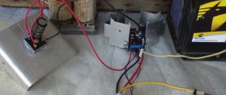
12 volt relay switch-on delay circuit
You can assemble a simple relay with your own hands. The easiest electronic time relay circuit to implement is assembled on the basis of the ne555 integrated timer. The relay is controlled by pressing external keys. 12V will be enough to operate the device. The relay can be powered via a power cable to the mains. A 12-volt battery can also temporarily support the operation of the relay.
The circuit of a simple time relay based on the NE 555 timer also has the following features:
- The unit that sets the time interval is a circuit of an AC resistor and an electrolytic capacitor. The delay interval for switching on the time relay depends on their rating
- With a resistor value of 500 kOhm and a capacitor of 220 μF, the delay range can be from 2 seconds to 3 minutes.
- An indicator of the relay's performance can be an LED connected in parallel to the coil.
This device can be used to both turn off and turn on electrical equipment with a time delay. To start the time countdown, you must press the “start” button, which starts the timer. The “stop” button is responsible for turning off the power and returning the relay-controlled device to its original state.
Greetings! I present to you several time relay and load shutdown delay circuits. The load can be either a light bulb or a TV. Let your imagination run wild. This circuit is needed to turn off something after a certain time interval.
Fig.1. Timer circuit for automatic load shedding
. With the ratings of the timing elements indicated in the diagram, the shutdown delay will be about 40 minutes (for micropower timers, this time can be significantly increased, since they allow R2 to be set with a higher rating). In standby mode, the device does not consume power, since transistors VT1 and VT2 are locked. Switching on is done by button SB1 - when pressed, transistor VT2 opens and supplies power to the microcircuit. At the output of timer 3, a voltage appears, which opens the transistor switch VT1 and supplies voltage to the load, for example, to the BL1 lamp. The button is blocked, and the circuit will remain in this state while capacitor C2 is charging, after which it will turn off the load. Resistor R3 limits the discharge current of the timing capacitor, which increases the reliability of the device. To obtain large delay intervals, capacitor C2 must be used with a low leakage current, for example tantalum from the K52-18 series. The following diagram is for turning off the load after 5-30 minutes in 5 minute increments by pressing the SA1 button. Thanks to the use of a micro-power timer with a high input resistance, it is possible to use timing resistors of significantly larger values (from 8.2 to 49.2 MOhm), which allows the time interval to be increased: T = 1.1 * C2 * (R1 + ... + Rn).
Fig.2. Timer circuit with extended time interval for load shedding
Circuits that allow you to directly (without a relay) control the disconnection of the network load are shown in Fig. 3 and 4. In them, a triac is used as a switch. Compared to the original, in the variants presented here, some ratings have been changed to allow devices to operate from a mains voltage of 220 V. In the circuit in Fig. 3, the load is turned on immediately when contacts SA1 are closed, and turned off with a delay determined by the ratings R2-C2 (for those indicated on scheme it is 11 s). Circuit R1-C1 ensures that the one-shot device starts when turned on.
Fig.3. Transformerless network load control circuit
Fig.4. Circuit for automatic shutdown of network load
In the second scheme (Fig. 4), the load will be turned on when initially connecting to the network or when pressing the SB1 button. To power the microcircuit, a reactance is used, which is capacitor C1 (it does not heat up, which is better compared to a voltage-damping active resistance, as was done in the previous circuit). Zener diode VD1 provides a stable supply voltage to the microcircuit, and diode VD3 allows you to reduce the readiness time of the circuit for frequent pressing of the button. The turn-off delay time can be adjusted by resistor R3 from 0 to 8.5 minutes. The timing capacitor SZ must have a small leakage.
Literature: For radio amateurs: useful diagrams, Book 5. Shelestov I.P.
Books on the subject of engines
For those who want (as my boss says) to “plunge into the problem,” I post good books on engines and electrical engineering in general for free download and review.
• V.L. Likhachev. Asynchronous electric motors. 2002 / The book is a reference book that describes in detail the design, operating principle and characteristics of asynchronous electric motors. Reference data is provided for engines of previous years of production and modern ones. Electronic starting devices (inverters), electric drives are described., djvu, 3.73 MB, downloaded: 7136 times./
• Bespalov, Kotelenets - Electrical machines / Transformers and electrical machines used in modern technology are considered. Their decisive role in the generation, distribution, conversion and utilization of electrical energy is shown. The basic theory, characteristics, operating modes, examples of designs and applications of electrical generators, transformers and motors are given., pdf, 16.82 MB, downloaded: 2317 times./
• MM. Katzman - Electrical Machines / Some say this is the best textbook on electrical engineering. The book discusses the theory, principle of operation, design and analysis of operating modes of electrical machines and transformers, both general and special purpose, which have become widespread in various branches of technology., pdf, 22.12 MB, downloaded: 2061 times./
• Electromash motor catalog / Asynchronous electric motors with squirrel-cage rotor - manufacturer’s catalog, pdf, 3.13 MB, downloaded: 1376 times./
• VEMZ engines catalog / Engine parameters and catalogue, pdf, 3.53 MB, downloaded: 1181 times./
• Dyakov V.I. Typical calculations for electrical equipment / Practical calculations for electrical equipment, theoretical information, calculation methods, examples and reference data., zip, 1.53 MB, downloaded: 2515 times./
• Karpov F.F. How to check the possibility of connecting several motors to the electrical network / The brochure shows the calculation of the electrical network for voltage fluctuations during the start-up and self-starting of asynchronous motors with squirrel-cage rotor and synchronous motors with asynchronous starting. The conditions under which starting and self-starting of engines are permissible are considered. The presentation of calculation methods is illustrated with numerical examples. The brochure is intended for qualified electricians as a guide when choosing the type of electric motors connected to a municipal or industrial power supply network., zip, 1.9 MB, downloaded: 1640 times./
• Operating manual for asynchronous motors / This manual contains the most important instructions for transportation, acceptance, storage, installation, commissioning, operation, maintenance, troubleshooting and troubleshooting for electric motors produced by Elektromashina. The operating manual is intended for three-phase asynchronous electric motors of low and high voltage series A, AIR, MTN, MTKN, 4MTM, 4MTKM, DA304, A4., pdf, 7.54 MB, downloaded: 2540 times./
• Catalog of AIR engines / Catalog of AIR engines - power from 0.12 to 315 kW; rotation speed 3000, 1500, 1000, 750 rpm; mains voltage 220/380 V, 380/660 V;, pdf, 1.07 MB, downloaded: 1044 times./
• Lomonosov, V.Yu.; Polivanov, K.M.; Mikhailov, O.P. Electrical engineering. / Lomonosov, V.Yu.; Polivanov, K.M.; Mikhailov, O.P. Electrical engineering. One of the best books on the basics of electrical engineering. The presentation begins with the very basics: it explains what voltage, current and resistance are, provides instructions for calculating the simplest electrical circuits, and talks about the relationship and interdependence of electrical and magnetic phenomena. Explains what alternating current is and how an alternating current generator works. It describes what a capacitor is and what an inductor is, what their role is in alternating current circuits. It is explained what three-phase current is, how three-phase current generators are designed and how its transmission is organized. A separate chapter is devoted to semiconductor devices: it talks about semiconductor diodes, transistors and thyristors; on the use of semiconductor devices for rectifying alternating current and as semiconductor switches. The achievements of microelectronics are briefly described. The last third of the book is entirely devoted to electrical machines, units and equipment: chapter 10 deals with direct current machines (generators and motors); Chapter 11 is devoted to transformers; AC machines (single-phase and three-phase, synchronous and asynchronous) are described in detail in Chapter 12; switches, electromagnets and relays are described in Chapter 13; Chapter 14 deals with electrical diagramming. The last, chapter 15, is devoted to measurements in electrical engineering. This book is a great way to learn the basics of electrical engineering, to understand the fundamental principles of the operation of electrical machines and units., zip, 13.87 MB, downloaded: 2653 times./
Another manual on motors: • Starting and protecting AC motors / Starting and protecting AC motors. Starting and braking systems for AC motors. Protection devices and fault analysis of AC motors. Guide to selecting protection devices. Manual from Schneider Electric, pdf, 1.17 MB, downloaded: 2042 times./
That's all, nothing more to say. I hope I explained the topic in detail. I look forward to questions and fair criticism in the comments!
Relay Coil Disconnection
When the relay coil is turned off, it is also possible to achieve a slow decline in the magnetic flux in the magnetic circuit (Fig. 2 b). For this, various dampers are used. A damper is a thick sleeve made of copper or aluminum, which is mounted on a common core with a retractor coil. This sleeve creates a secondary circuit. When the main magnetic flux disappears when the RP is opened, a current is induced in the sleeve, which, according to Lenz’s rule, tends to maintain the main flux. The greater the mass of the damper, the longer the relay time delay. The aluminum base of the relay also plays the role of a damper. Various relay delay ranges (0.3-5.5 sec) are achieved through the use of additional removable dampers.
It should be borne in mind that the RE-500 type relay is designed for direct current, and it is connected to the control circuit of AC motors through rectifiers.