Very few people understand the essence of electricity. Concepts such as “electric current”, “voltage”, “phase” and “zero” are a dark forest for most, although we encounter them every day. Let's get a grain of useful knowledge and figure out what phase and zero are in electricity. To teach electricity from scratch, we need to understand the fundamental concepts. We are primarily interested in electric current and electric charge.
Daily newsletter with useful information for students of all directions - on our telegram channel.
Let's understand the basic terms
Everyone encounters such terms as “phase” and “zero” in their lives every day. All of them are closely related, because they relate to electricity, and this is something without which the life of a modern person is unthinkable. To understand their nature and more or less learn to understand electrics, you should first understand a number of fundamental concepts.
Let's start with the basics
Electric charge is a characteristic that determines the ability of various bodies to be a source of an electromagnetic field. The carrier of such waves is the electron. By creating an electromagnetic field, you can “force” electrons to move. This is how current is generated.
Current is a clearly directed movement of electrons along a metal conductor under the influence of an existing field.
Types of current
The current can be constant or alternating. A current that does not change in value over a period of time is a current of constant value. A current, the magnitude of which, like the direction, changes over time, is called variable.
Constant current sources - batteries, batteries, and so on. Alternating current is “suitable” for household and industrial sockets in homes and businesses. The main reason for this lies in the fact that this type of current is much easier to obtain physically, convert to different voltage levels, and transmit through electrical wires over vast distances without significant losses.
Basic characteristic of alternating current
Alternating current is usually a sine wave, or sinusoidal current. It can be characterized as follows: first it increases in one direction, reaching its maximum value (amplitude), then it begins to decline. At some point in time it becomes equal to “0” and then begins to increase again, but in a completely opposite direction.
"Phase", "zero" and "ground"
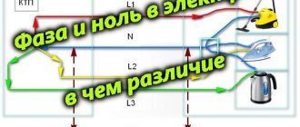
The simplest case of an electrical circuit through which a sinusoidal current moves is a single-phase circuit. It consists, as a rule, of three electrical cables: along one of them, electricity approaches devices and lighting elements, and through the second, it “leaves” in the opposite direction - away from the consumer. The third conductor is the “ground”.
The wire through which electricity reaches electrical consumers is called a phase, and the cable used for return movement is called zero.
The most efficient network for transmitting electric current is a three-phase system. It includes three phase cables and one return cable - zero. This type of current is suitable for all residential areas. Immediately before entering the apartment, the electric current is divided into phases. Each phase is “assigned” one zero. The advantages of such a system are that with a balanced load, the current through zero (and in such a system there is only one - common) is zero.
To avoid mixing up the wires and preventing a short circuit, each wire is painted a different color. However, the color of the wire does not guarantee its purpose!
The “earth” does not carry any electrical load, but serves as a kind of safety element. At that moment, when something in the power supply system gets out of control, the ground wire will prevent electric shock - it will “drain” all excess voltage, that is, it will be discharged to the ground.
Phase and zero: their meaning in the power supply network
Electricity is supplied to consumer sockets from substations, which reduce the incoming voltage to 380 V. The secondary winding of such a transformer has a “star” connection - its three contacts are connected to each other at the “0” point, the remaining three outputs go to the “A” / “B” terminals "/"WITH".
The wires connected at point “0” are connected to “ground”. At the same point, the conductor is divided into “zero” (indicated in blue) and a protective “PE” cable (yellow-green line). This model of wiring is used in all houses currently being built. It is called the “TN-S” system. According to this diagram, three phase cables and two indicated zeros are suitable for the distribution equipment of the house.
In houses, enterprises and buildings of old construction there is often no “PE” conductor and therefore the circuit turns out not to be five-wire, but four (it is designated as “TN-C”).
All electrical wires from the substations are connected to the panel, forming a three-phase system. Then there is a division into separate entrances. Each of the entrance apartments is supplied with only one phase voltage - 220 V (wires “O” / “A”) and a protective “PE” cable.
With this scheme, the entire load on the power supply system is distributed evenly, since on each floor of the house specific panels are wired and connected to a specific 220 V power line.
The supply voltage circuit is a “star”, which exactly repeats all the vector characteristics of the supply substation. When there are no consumers in the sockets, no current flows in this circuit.
This connection scheme has been worked out for years. It confirmed its right to use by being recognized as the optimal of all existing ones. However, in it, as in any device, mechanism or device, all kinds of breakdowns and malfunctions may periodically appear. As a rule, they are associated with poor quality electrical connections or complete cable breaks in some places in the circuit.
Cases of breaks in the conductive circuit
If a zero/phase break occurs inside a single apartment, then the connected device, as a result, will not function.
A similar situation will arise if the contacts of the wires of any of the phases supplying the access panel are broken. In this case, all apartments receiving power from this power line will not receive electricity. At the same time, in the two remaining circuits the devices will function as before.
From these diagrams it is clear that a complete power outage in apartments is associated with a break in one of the wires. This does not lead to damage or failure of the devices. The most serious situation is a break between the grounding loop and the central connection point of all consumers.
In this case, the entire electric current stops flowing along the working zero to the “ground” (AO, VO, CO) and begins to move along the path AB/BC/CA to which 380 V is supplied.
A “phase imbalance” occurs. In phases with a higher load, the voltage will be less, and with a lower load, more and can reach significant values, close to 380 V. This will cause damage to the insulating materials, heating and failure of the equipment. A system of protection against overloads and high voltages mounted in apartment panels allows you to prevent such cases and protect expensive equipment.
Household electrical wiring.
Initially, electricity is generated at a power plant. Then, through the industrial power grid, it enters the transformer substation, where the voltage is converted to 380 volts. The connection of the secondary windings of the step-down transformer is made according to the “star” circuit: three contacts are connected to the common point “0”, and the remaining three are connected to terminals “A”, “B” and “C”, respectively. For clarity, a picture is provided.
The combined contacts “0” are connected to the grounding loop of the substation. Also here the zero is split into:
- Working zero (shown in blue in the picture)
- PE conductor performing a protective function (yellow-green line)
The zeros and phases of the current from the output of the step-down transformer are supplied to the distribution panel of the residential building. The resulting three-phase system is distributed across panels in the entrances. Ultimately, a phase voltage of 220 V and a PE conductor, which performs a protective function, enters the apartment.
So, what is zero phase current ? A zero is a current conductor connected to the ground loop of a step-down transformer and serves to create a load from the current phase connected to the opposite end of the transformer winding. In addition, there is a so-called “protective zero” - this is the PE contact described earlier. It serves to drain current when a technical malfunction occurs in the circuit.
This method of connecting residential buildings to the city power grid has been proven for decades, but it is still not ideal. Sometimes malfunctions appear in the above system. Most often, they are associated with poor connection quality in a certain section of the circuit or a complete break in the electrical wire.
Features of the neutral wire
The neutral wire prevents undesirable situations during emergency operation. Without it, in the event of a phase short circuit of two phases, the voltage in the third phase will instantly increase by √3 times. This will have a detrimental effect on the equipment that powers this source. If there is a zero in this situation, the voltage will not change.
If one of the phases in a three-phase three-wire system (without zero) breaks, the voltage on the two remaining phases will decrease. They will be connected in series, and with this type of connection the voltage is distributed among consumers depending on their resistance. If one of the phases in a three-phase four-wire system breaks, the voltage in the two remaining phases will not change its value.
Fuses are not installed in the neutral wire due to its great importance, because its breakage is undesirable
Since most of the time electrical installations operate, the current in this wire is either zero or insignificant, there is no point in making it the same cross-section as the phase wire cross-section. Most often, for reasons of economy, it has a smaller cross-section of the conductor than the cross-section of the conductors of the phases in one electrical installation. If the protective wire is not combined with the neutral wire, its cross-section is half that of the phase wire.
Coloring for 220V and 380V single-phase and three-phase voltage
In a three-phase network, wires and buses were previously colored as follows:
Phase A
Yellow color
Phase B
Green color
Phase C
Of red color
To make it easier to remember the order of colors, electricians used the abbreviation ZH-Z-K.
From 01/01/2011, new standards were introduced in accordance with GOST R 50462-2009 ():
Phase A
Brown
Phase B
Black
Phase C
Grey
Now it's time to switch to abbreviations - K-H-S! Subjectively speaking, this marking is inferior in clarity to the previous color scheme Zh-Z-K.
Imagine that there is poor lighting in the control room or room, dust on the wires? Which do you think your eye is better at distinguishing between yellow and green or brown and black? The rules in this case stipulate the need for letter designation and marking of the cores, in addition to color.
Classification of power line neutrals
The purpose of power lines is very diverse. There is also a variety of equipment to protect them from leaks and short circuits. In this regard, neutrals are classified into three types:
- solidly grounded;
- isolated;
- effectively grounded.
If the power line with voltage from 0.38 kV to 35 kV is short and the number of connected consumers is large, then a solidly grounded neutral is used. Consumers of a three-phase load receive power thanks to three phases and zero, and consumers of a single-phase load receive power from one of the phases and zero.
With an average length of power lines with voltages from 2 kV to 35 kV and a small number of consumers connected to this line, insulated neutrals are used. They are widely used for connecting transformer substations in populated areas, as well as powerful electrical equipment in industry.
In networks with a voltage of 110 kV and higher, with a large length of power lines, an effectively grounded neutral is used.
Briefly about the main thing
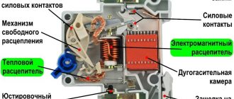
SIP brand cables are the next generation of wires for overhead power lines, significantly increasing the efficiency of their operation. In domestic use it is mainly used when laying lines from the transformer to the consumer and making branches from them. One of the main advantages when using it is the ease of installation and operation, which allows a person to operate it without much experience in such work. But in any case, we must remember that all manipulations to connect electrical wiring to the network must be carried out by qualified electricians.
Computer technology, radio electronics, electrical engineering
Reaction of electrical appliances to zero loss
If the common neutral wire in a multi-story building breaks, consumers will feel it as a result of a voltage surge in their electrical appliances.
The main factors that can lead to loss of power to the common zero:
- emergency situation at the substation;
- outdated wiring;
- The wiring installation was not done very well.
The phase to which more consumers of the apartment building are connected will be overloaded. The tension in it will decrease. In the phase to which the least number of consumers are connected, the voltage will increase sharply.
This will have a negative impact on the devices - a decrease in voltage will cause them to operate ineffectively, and an increase in voltage may lead to the failure of those that are currently connected. To protect yourself from such a situation, you need to install an individual surge suppressor in the panel that supplies a separate apartment. As soon as the voltage begins to exceed permissible values, the limiter will quickly turn off the power.
If a zero break occurs directly in the apartment, the electricity will be lost completely, but at the same time the phase will not be turned off. The danger is that it can go right to the neutral wire. And if any electrical device was previously grounded to it, the body of this electrical device will be energized, or, more simply put, it will begin to “beat with current.”
The main factors that contribute to the loss of zero directly in the apartment can be called:
- unreliable connection of contacts;
- incorrectly selected conductor cross-section;
- outdated wiring.
These factors lead to excessive heating of the conductor. Due to the increased temperature, the place where the contacts are connected oxidizes, and the wire strands overheat. And this, in turn, can lead to a fire.
Why is PE protective conductor needed?
A protective conductor or PE is necessary for additional protection of the home. In the event of a short circuit, it diverts current from the location where the wiring is damaged, thereby protecting people from electric shock and property from fire.
In such a network, the load is distributed evenly, since each floor of an apartment building is wired in phases.
The electrical system connected to residential premises is a “star”, which repeats all the vector characteristics of the transformer substation.
Such a system is reliable and optimal, but it also has its drawbacks, since malfunctions periodically occur. Most often, power outages are associated with poor quality wires, as well as poor-quality connections.
What is the danger of damaging the neutral wire?
Overheating of the neutral wires due to poor contact.
Zero is damaged due to mechanical stress, short circuits, poor-quality connections or as a result of old wiring. Neutral break:
- PEN conductor in the power cable - there is only one ground loop left, which is not visually noticeable;
- combustion of a conductor in the switchboard - phase conductors become distorted, the voltage increases to 380 V;
- there is a break in the apartment panel - the second phase remains in the sockets, household appliances are not powered from them.
Causes of short circuit
A short circuit becomes possible when the current does not pass through “zero” to the ground loop A0, B0 and C0. Instead, the currents move along the external circuits AB, BC and CA, which are powered by a voltage of 360 volts. Thus, on one panel of the apartment there may be too little voltage, since the frugal tenant has turned off all electrical appliances, while on the other, a voltage close to linear is formed - 360 volts. This causes damage to the wires. The devices, in turn, overheat as a result of the supply of off-design currents to them.
To avoid such a situation and protect against a sudden surge in voltage, there are protection devices that are installed inside apartment panels. They are also placed in the housing of expensive electrical appliances to prevent breakdowns, for example, in refrigerators and freezers.
What is grounding and neutral wire
The neutral conductor also balances the potentials in several phases. According to the PUE, the task of the neutral is to provide current to consumers. It must be connected to a solidly grounded neutral point of the transformer. In private houses and apartments where single-phase electrical networks are used, there must be two cables for the equipment to operate: phase and neutral. “Zero” is connected to “ground”, and its potential must be equal to 0. It is connected to “ground” using a ground loop.
Accordingly, there should be no voltage. If communication with it is disrupted during operation of the equipment, it will be under the same voltage as in the phase, respectively - 220. On modern diagrams it is designated by the letter N, and in Soviet documents, already outdated, the number 0 was used. According to the PUE, the cable must cover with blue insulation.
The grounding conductor, according to the PUE, is needed for safety purposes. Under normal conditions, there is no voltage on it, and it works as a conductor only if the insulation of the conducting phase or neutral is damaged. Accordingly, grounding is necessary so that in the event of a breakdown no additional problems arise. For example, when your refrigerator’s protection is broken, and the refrigerator itself is not grounded, touching it will be equivalent to touching the 220 V phase. But if the refrigerator is grounded, it will not give an electric shock, since the potential will go into the ground.
The protective conductor is designated by the letters “PE”. According to the rule, its insulation must be painted in yellow and green stripes. If the diagram has the designation “PEN”, it means that the neutral and protective wires are combined into one. Such a cable should be painted blue with yellow and green stripes at the ends.
To equalize different voltages, all ends of the phase windings are connected into a node, which is called a neutral point, for which a neutral wire is used when connected in a “star”. The star circuit with neutral is used in practice, because in it, at any load, there is no phase imbalance in voltage, i.e. all phase voltages are equal.
If you take into account all of the above, then you probably understand the critical importance of a neutral cable that equalizes voltage in several phases, because its absence threatens with serious problems - from damage and loss of equipment to fires and even the risk of fatal electric shock to a person.
Designation of colors on electrical diagrams
The number of colors used in the work depends directly on the specific scheme. If the work is carried out according to generally accepted standards, then an experienced electrician will easily understand your network in the future. You don’t have to use additional devices to determine the phase; knowledge of color designation is enough. The standard palette is:
- zero – blue;
- earth – yellow;
- phase – red.
In a single-phase network, one color is used, but if more massive networks are used, the phase can be marked in black and green.
When branching a single-phase network from a three-phase network, the same colors are used.
Before you begin any electrical wiring work, it is important to know the color codes for each wire. Firstly, for the sake of your own safety, and secondly, this approach will provide maximum comfort. Such knowledge simplifies the installation process and future network maintenance. You don't have to use a special screwdriver every time to determine the phase. Experienced electricians will be able to “speak” the same language using color-letter marking standards.
What is grounding?
Grounding or protective conductor in accordance with clause 1.7.34 of the PUE is intended exclusively for electrical safety purposes. Under normal conditions, it is not energized and acts as a conductor only in cases of failure of the insulation of the phase or neutral conductor. At the same time, at the electrical installation itself, it reduces the potential to bladeless.
Why is grounding needed?
- In simple terms, grounding is necessary only in case of breakdown. For example, you have a breakdown in the insulation of your washing machine. If it is not grounded, then touching it is equivalent to touching a phase wire. If it is grounded, then nothing will happen, since the excess potential will go into the ground through grounding.
- Grounding can be done using different schemes depending on your capabilities and the power supply circuit. We will consider this issue below.
- The protective conductor in the diagrams is usually designated by the symbols “PE”. The conductor itself should be made of yellow-green wire.
- On some diagrams you may see the designation “PEN”. This means the combination of the neutral and protective wires. We'll talk about it a little lower. The color of such a wire, according to clause 1.1.29 of the PUE, should be blue with yellow-green stripes at the ends.
Connection diagrams for neutral wire and grounding
Now you know how to distinguish the neutral wire from the ground and understand that both are connections to the ground. Now you can consider possible schemes for connecting the neutral wire and grounding. All of them are clearly specified in clause 1.7.3 of the PUE. We will consider only circuits with a solidly grounded neutral that are used in our electrical networks.
TT system
- First of all, let's consider a CT system in which the neutral wire is connected to the grounding of the transformer, and the grounding to an independent source. This method is used very rarely, and the cost of installing such a system is the highest.
- Much more commonly used are TN type systems that use PEN conductors. That is, along the entire length or in certain sections, the neutral and protective conductors are laid with one wire, or are connected to one grounding point.
TN-S system
- The most optimal in this case in matters of electrical safety is the TN-S system. In it, the neutral and protective conductors are connected to a single grounding point, but along their entire length they are made of separate conductors.
TN-C system
- Much more often you can find the TN-C system, which is quite easy to implement with your own hands. In it, the neutral wire and grounding are made of one wire along the entire length. But this is the least safe option in terms of electrical safety.
TN-CS system
- And the last possible option is the TN-CS system. As the name implies, it combines the two previous systems. That is, in one section the neutral and grounding are laid together, and in the second section they are separated.
Rules for connecting the neutral wire and grounding
Knowing the possible connection diagrams for grounding and the neutral wire, we can talk about the rules and requirements for their connection. After all, although they are not significant, they differ. In addition, we hope that we will explain the frequently asked question of why the neutral wire should be grounded.
- First of all, let's talk about the TT system. According to clause 1.7.59 of the PUE, this system can only be used in exceptional cases when none of the TN systems can provide the required level of protection.
Note! When using the TT system, the use of RCDs is mandatory. Moreover, the PUE standards impose separate requirements on them in terms of operating current.
- But for the TN system everything is not so simple. According to clause 1.7.61 of the PUE, at the entrance to the building or electrical installation, they must be re-grounded. Let's figure out why this is necessary.
- In the TN system, as we already know, the neutral and protective conductors are mounted with one wire. If this joint wire breaks, it turns out that the neutral and protective wires form a single whole. After all, they are not connected to the ground.
- If we do not have a connection to the ground, then, as we already know, when you turn on any electrical appliance or even a light bulb, the neutral wire ends up under phase voltage.
- But for a TN system, the neutral and phase wires are partially or completely combined. That is, the grounding wire is also under phase voltage. And our phase wire is connected to the body of our washing machine, hair dryer, refrigerator and other electrical equipment. It turns out that phase voltage will appear on their body. And if you touch them, you will receive an electric shock.
Precautionary measures
Ensuring the electrical safety of your home is primarily the task of the owners themselves. It is easier to prevent a situation than to correct its consequences. Not only homeowners in high-rise buildings, but also people living in the private sector are at risk of a neutral wire break. There are several ways to protect yourself from troubles.
For example, re-ground the neutral wire. The easiest way to carry out such work is in your home. In new buildings, according to the new rules, the protective zero is already included in the electrical network of the house; in other cases, it is worth consulting the relevant organization about the possibility of connection. Repeated grounding will ensure safe drainage of current into the ground, which will protect both equipment and people.
A good solution to surge voltage is to install a stabilizer. But, this option is more acceptable for the private sector due to the large dimensions of the device. It will not be possible to install it comfortably in a small apartment.
In conditions of limited space, other protection against neutral wire breakage is suitable. We are talking about modular devices installed in the floor electrical panel. They are compact and reliable in operation. Of course, they cannot equalize the voltage, but they can disconnect an apartment or house from the emergency network in the event of voltage surges as clearly as possible.
Among the models presented on the market, the buyer will find both inexpensive samples of devices that work only for automatic de-energization, as well as more advanced equipment that allows you to record the values of emergency values, as well as independently turn on the current after eliminating the danger.
With proper knowledge of electrical engineering, installation of protective devices can be done with your own hands. Otherwise, it is better to invite a specialist.
Re-grounding the neutral wire
Re-grounding of the neutral conductor is protection installed at the intervals specified by the rules of the Electrical Installation Code along the entire length of the neutral. The task of re-grounding includes reducing the voltage in the neutral wire and electrical appliances that have been grounded relative to the ground. This property is useful as protection against a break in the neutral wire and in the event of a breakdown of electrical voltage on the housing of electrical devices.
When creating protection in the electrical network, try to select the neutral and protective conductors in such a way that in the event of a short circuit to the metal body of the equipment, a short circuit in the network or melting of the fuses occurs. Usually, when a circuit breaker is installed, this factor causes it to trip.
Important! If a short circuit occurs in a neutralized electrical circuit, the resulting voltage must be three times higher than the rated current.
The neutral must be continuous from each electrical installation housing to the neutral conductors of the electricity sources.
Determining the resistance of the zero/ground loop
Measuring the loop resistance value is the key to uninterrupted operation of electrical appliances. This should be done from time to time, since the main causes of equipment breakdowns lie in short circuits and overloads of electrical networks. Measuring the resistance will eliminate such troubles.
What is this loop
This loop is a circuit resulting from the connection of the “zero” to the grounded neutral. It is precisely the closure of this circuit that will form this loop.
The main task of measuring the resistance of this loop is to reliably protect equipment and cables from overloads during operation. High resistance will cause an excessive increase in the temperature of the power line, and as a result, a fire. Air humidity, temperature, time of day have a significant impact on the quality of electrical wiring - all this affects the condition of the electrical network.
How phase wires are painted
When working with wiring, phase wires pose the greatest danger. Touching the phase, under certain circumstances, can become lethal, which is probably why bright colors were chosen for them. In general, the colors of electrical wires allow you to quickly determine which of a bunch of wires are the most dangerous and work with them very carefully.
Coloring of phase wires
Most often, phase conductors are red or black, but other colors are also found: brown, lilac, orange, pink, purple, white, gray. Phases can be painted in all these colors. It will be easier to deal with them if you exclude the neutral wire and ground.
In the diagrams, phase wires are designated by the Latin (English) letter L. If there are several phases, a numerical designation is added to the letter: L1, L2, L3 for a three-phase 380 V network. In another version, the first phase is designated by the letter A, the second by B, and the third by C .
Ground wire color
By modern standards, the ground conductor is yellow-green. It usually looks like yellow insulation with one or two longitudinal bright green stripes. But there are also transverse yellow-green stripes in color.
Grounding may be this color
In some cases, the cable may only have yellow or bright green conductors. In this case, the “earth” has exactly this color. It is displayed in the same colors on diagrams - most often bright green, but it can also be yellow. Signed on circuit diagrams or on ground equipment in Latin (English) letters PE. The contacts to which the “ground” wire must be connected are also marked.
Sometimes professionals call the grounding wire “neutral protective”, but do not be confused. This is an earthen one, and it is protective because it reduces the risk of electric shock.
What color is the neutral wire?
Zero or neutral is blue or light blue, sometimes blue with a white stripe. Other colors are not used in electrical engineering to indicate zero. It will be like this in any cable: three-core, five-core or with a large number of conductors.
What color is the neutral wire? Blue or cyan
“Zero” is usually drawn in blue on diagrams and signed with the Latin letter N. Experts call it a working zero, since, unlike grounding, it participates in the formation of the power supply circuit. When reading a diagram, it is often defined as "minus", while the phase is considered "plus".
How to check the correctness of marking and wiring
Wire colors in electrical engineering are designed to speed up the identification of conductors, but relying only on colors is dangerous - they could be connected incorrectly. Therefore, before starting work, you should make sure that you have correctly identified their affiliation.
Take a multimeter and/or an indicator screwdriver. It’s easy to work with a screwdriver: when you touch a phase, the LED built into the housing lights up. So it will be easy to identify phase conductors. If the cable is two-wire, there are no problems - the second conductor is zero. But if the wire is three-wire, you will need a multimeter or tester - with their help we will determine which of the remaining two is phase and which is zero.
Determining the phase wire using an indicator screwdriver
We set the switch on the device so that the selected jackal is more than 220 V. Then we take two probes, hold them by the plastic handles, carefully touch the metal rod of one probe to the found phase wire, the second to the supposed zero. The screen should display 220 V or the current voltage. In fact, it may be significantly lower - this is our reality.
If 220 V or a little more is displayed, this is zero, and the other wire is presumably “ground”. If the value is less, we continue checking. With one probe we again touch the phase, with the second - to the intended grounding. If the instrument readings are lower than during the first measurement, there is “ground” in front of you and it should be green. If the readings turn out to be higher, it means that somewhere there was a mistake with “zero” in front of you. In such a situation, there are two options: look for exactly where the wires were connected incorrectly (preferable) or simply move on, remembering or noting the existing position.
So, remember that when testing a phase-zero pair, the multimeter readings are always higher than when testing a phase-ground pair.
And, in conclusion, let me give you some advice: when laying wiring and connecting wires, always connect conductors of the same color, do not confuse them. This can lead to disastrous results - at best, equipment failure, but there may also be injuries and fires.
What is a grounding cable for?
Grounding is provided in all modern electrical household devices. It helps reduce the current to a level that is safe for health, redirecting most of the flow of electrons to the ground and protecting the person touching the device from electrical shock. Also, grounding devices are an integral part of lightning rods on buildings - through them, a powerful electric charge from the external environment goes into the ground, without causing harm to people and animals, or causing a fire.
To the question - how to identify a grounding wire - one could answer: by the yellow-green sheath, but color marking, unfortunately, is often not observed. It also happens that an electrician who does not have sufficient experience confuses a phase cable with a neutral cable, or even connects two phases at once.
To avoid such troubles, you need to be able to distinguish conductors not only by the color of the sheath, but also in other ways that guarantee the correct result.