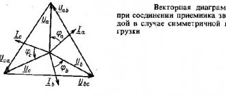
Three-phase load connected in star connection
If the loads (receivers) are connected in a three-phase circuit according to the “star” circuit (Fig. 1), then phase voltages are applied to the load resistances.
Linear currents are equal to phase currents and are determined by Ohm’s law: and the current in the neutral is equal to the vector sum of these currents: I N
=
I A
+
I B
+
I C
.
At symmetrical voltages UA
,
UB
,
UC
and the same resistances
RA
=
RB
=
RC
=
R
the currents
IA
,
IB
,
IC
are also symmetrical and their vector sum (
IN
) is zero. Then
IL =
IФ
=
UФ ¤ R
;
IN
= 0.
If the load phase resistances are not the same, then some current IN
No. 0. This is illustrated in vector diagrams (Fig. 2).
The power of a three-phase load is the sum of the phase powers: S P =
PA + PV + PC.
When the load is symmetrical and purely resistive, we have
S P = 3
PF
=
3 UФ × IФ
.
With a mixed (active-inductive or active-capacitive) load:
S P = 3
× UФ × IФ × cos j = Ö3 × UL × IL × cos j
.
S Q = 3
× UФ × IФ × sin j
=
Ö3 × UL × IL × sin j
.
S S = 3
× UФ IФ = Ö3 × UЛ × IЛ
.
Where can I buy
You can purchase stabilization devices as quickly as possible at your nearest specialty store. The optimal option, in terms of price-quality ratio, remains purchasing from the AliExpress online store. Mandatory long waits for parcels from China are a thing of the past, because now many goods are in intermediate warehouses in destination countries: for example, when ordering, you can select the “Delivery from the Russian Federation” option:
| Voltage stabilizer 1.5 kW | voltage stabilizer DELIXI 10 kVA | Voltage stabilizer 15 kVA |
| Voltage stabilizer TM-15000VA | Voltage stabilizer HOME SNR 1/220 0.5kVA | Voltage stabilizer/regulator |
Emergency modes of a three-phase circuit when connecting the load to a star
Emergency modes occur when there are short circuits in the load or in lines and wire breaks. Let's look at some typical emergency modes.
Break of neutral wire with unbalanced load
In balanced IN
= 0, therefore, a break in the neutral wire does not lead to a change in currents and voltages in the circuit and this mode is not an emergency.
However, with an asymmetrical load, IN
¹ 0, so a break in the neutral leads to a change in all phase currents and voltages.
On the voltage vector diagram, the “0” point of the load, which previously coincided with the “ N
” point of the generator, is shifted so that the sum of the phase currents is equal to zero (Fig. 3). Voltages on individual phases can significantly exceed the rated voltage.
Phase loss with symmetrical load in a circuit with a neutral wire
When a wire breaks, for example, in phase A, the current in this phase becomes zero, the voltages and currents in phases B and C do not change, and a current appears in the neutral wire
I N =
I B + I C.
It is equal to the current that flowed in phase A before the break (Fig. 4).
Phase loss with symmetrical load in a circuit without a neutral wire
If, for example, phase A of the resistances RA and RB is broken, they are connected in series and a linear voltage UBC is applied to them. The voltage at each of the resistances is equal to the phase voltage in normal mode. The zero point of the load on the stress vector diagram is shifted to line BC and at RB = RC is located exactly in the middle of the segment BC (Fig. 5)
Short circuit
When a load phase is short-circuited in a circuit with a neutral wire, the current in this phase becomes very large (theoretically infinitely large) and this leads to emergency shutdown of the load by the protection. In a circuit without a neutral wire, when, for example, phase A is closed, the zero point of the load shifts to point “A” of the generator. Then linear voltages are applied to the resistances of phases B and C. Currents in these phases increase by a factor, and the current in phase A increases by 3 times (Fig. 6).
Short circuits between the linear wires in both circuits lead to emergency load shutdown.
Laboratory work No.
13
Three-phase load connected according to the “STAR” circuit
Goal of the work:
Investigate a three-phase circuit connected according to a “STAR” circuit in various
For a three-phase circuit with a “STAR” connection with symmetrical and asymmetrical loads, use a multimeter to measure the effective values of phase and line voltages and the current in the neutral wire. Calculate line currents and phase powers. Draw vector diagrams of voltages and currents to scale.
1.Assemble a circuit with a symmetrical load (RA= RB= RC=1kOhm) according to the diagram.
2.Measure the effective values of voltage and current in the neutral wire according to the table. 1 and calculate the currents and phase powers.
3.Repeat measurements and calculations for an unbalanced load (RA=1 kOhm,
RB=680 Ohm, RC=330 Ohm).
4. Construct vector diagrams of voltages and currents to scale.
Causes
A three-phase network consists of two parts - high voltage and low voltage. A substation with a step-down transformer is usually installed between them. In the high-voltage part, the phases are loaded evenly; imbalance occurs in the low-voltage part and is associated with the peculiarities of load distribution between the phase buses.
There are two different types of phase imbalance:
- the modules of the voltage vectors are different in size, the angle between them is the same (120°);
- It occurs much less frequently in practice when, in addition to different voltage modules, the angles between them are also different.
The voltage diagram shows the parameters of an ideally operating three-phase circuit and their change when a imbalance occurs.
A drop/increase in phase voltage according to Ohm's law occurs with an increase/decrease in resistance (load). Therefore, one of the reasons for the occurrence of imbalance will be the different number and power of electrical devices “sitting” on each individual phase.
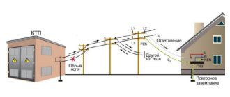
In ideally operating three-phase circuits, the current through the neutral wire is zero. If a imbalance occurs, currents appear on it that compensate for the voltage asymmetry. That is why a break (“burnout”) of the neutral wire is another reason for the appearance of misalignment.
Image showing the result of the neutral wire “burning out”.
A short circuit of one of the phases to ground, which leads to the operation of the network in skew mode, is rarely found among the causes of voltage inequality across phases. In some cases, such emergency operation is permitted when it is necessary to provide electricity to users.
Signs of unstable operation of electrical appliances caused by phase imbalance
Regardless of the reasons for the imbalance, it is necessary to know and identify its signs. In an apartment or private house with electrical appliances, the following actions can occur due to voltage asymmetry and more:
- lighting devices such as fluorescent lamps or other types using energy-saving technology will begin to flicker;
- incandescent light bulbs will burn brightly or, on the contrary, dim;
- household appliances (iron, TV and others) will stop turning on;
- the switch became warm to the touch;
- sparks appeared in the socket, crackling and clicking sounds were heard;
- There are clicks in the shield and the circuit breakers are triggered.
If the above symptoms are detected, you should disconnect all devices from the network, only then begin to search for the causes. If you lack knowledge in the field of electrical engineering, it is better to contact a specialist.
Zero burnout: accident or inevitability
You can deal with electricity problems correctly if you become familiar with zero burnout. If you have heard from your friends the phrase that electrical appliances and expensive equipment burned out in the apartment due to a voltage drop, this means that their power supply is not 220V, but 380V. Where does the 380 Volt voltage in the electrical network come from? Often, this is due to a break in the zero, or, as is customary in the vocabulary of electricians, burnout of the zero. Why does the zero burn out? To understand this, let’s consider in general terms what an electrical network is. An electrical network is a set of electrical installations through which electricity is transmitted and distributed from the power plant to the end consumer.
Negative consequences of misalignment
The operation of a three-phase network with phase imbalance leads to the following negative actions.
- The imbalance causes an increase in equalizing currents, thereby increasing the energy consumption for equipment consumption.
- A phase voltage deviation exceeding the rated value in the absence of circuit breakers can damage household or industrial electrical equipment.
- A voltage deviation downward from normal will create the following problems for the equipment: the load on the electric motors will increase, their power will drop, even higher starting currents are required to start, the electronics will malfunction, and some devices simply will not turn on.
- The operating life of the equipment in phase imbalance mode will be shorter. Resource indicators will not correspond to passport data.
- Phase imbalance caused by a broken neutral wire can dramatically increase the risk of electric shock. The grounding device bus at the transformer substation loses connection with the local ground loop, thereby leaving the user without protection.
Standards for phase imbalance
In practice, there are no working three-phase networks in which there is no phase imbalance. This is due to the peculiarities of electrical equipment, the operating principle of which, from the point of view of economic feasibility, excludes symmetrical design (welding machines, induction furnaces, household consumers). In addition, for example, in apartment buildings there is a probabilistic factor associated with the lack of any system for connecting electrical household appliances. The presence of several switching power supplies, for example for computers, makes their behavior unpredictable in a three-phase network.
In addition to evenly distributing the load across phases, designers should consider the above factors to deliver a certain quality of power to users. In some cases, an intractable problem can be solved by regulations on permissible phase misalignment, indicated in the following regulatory documents: PUE (Rules for the Construction of Power Installations), GOST 31098 - 97 defining power quality standards and the set of rules SP31-110.
Parameters that must not be exceeded:
- maximum deviation of phase currents: for those measured in the input switchgear (IDU) - 15%,
- for those measured in the distribution board (DP) - 30%.
- in reverse sequence - 2%,
The above standards must be observed in all possible operating modes of three-phase electrical networks. Exceptions are regimes caused by Force Majeure circumstances.
How to determine phase imbalance
The simplest and therefore most used is control of the maximum deviation of phase currents. Using current clamps, the current strength is measured at the maximum full load on each conductor of an individual phase in an ASU or distribution switchboard. The dimensions of the pliers are compact enough to get to any conductor located in cramped conditions among other conductors.
After you determine and record the readings, you should perform an easy comparative calculation for phase current deviations. Indications must comply with the standards.
Elimination of phase imbalance
If the measurement results reveal the presence of phase voltage asymmetry, measures should be taken to eliminate the imbalance. Protection against phase imbalance in a three-phase network is performed in the following ways.
- At the design stage, the load should be evenly distributed among the phases. Devices with single-phase power supply should not focus on one conductor, leaving others unloaded. In addition to the quantitative distribution by phase, the power characteristics of electrical devices should be taken into account.
- In previously commissioned three-phase networks, where each phase was not designed for overload, if possible, the energy consumption pattern should be changed. In a crisis situation, it is necessary to change the consumer's power.
- An insufficiently effective way to provide the required voltage on each phase of a three-phase circuit is the use of voltage stabilizers.
Three-phase voltage stabilizers structurally include single-phase ones, which respond to changes in parameters specifically in their phase. Raising and lowering tension causes a response to others. This may in some cases cause a secondary distortion with different parameters. The impossibility of 100% guarantee of protection against the consequences of phase imbalance is the main drawback of voltage stabilizers. - The use of a balun transformer in a three-phase power system allows you to equalize the voltage not only on a single specific phase, but to ensure the symmetry of the voltages on all three in accordance with the required standards.
In addition, the device smoothes out the transient voltage when connecting powerful asynchronous motors, chokes, transformers and other similar equipment to the network. The device is able to eliminate phase imbalance in a wide range of voltage values. - A voltage stabilizer and balun transformer are expensive devices, and it is not always possible to use them. There is a fairly simple and effective way to prevent critical phase imbalance - the use of a special relay.
If the three-phase network parameters fall outside the set range, the relay will turn off the power source. When the parameters are restored to acceptable values, the relay will automatically resume power supply.
A responsible attitude towards uniform distribution of the load across phases does not guarantee the avoidance of imbalance. No one is safe from a break in the neutral wire; the connecting contact can “burn out” at any time due to overheating. Therefore, recommendations for equipping a three-phase network with skewing protection devices should be heeded. One-time costs will preserve the functionality of more expensive electrical equipment operating from a three-phase network.
The need for verification
Dielectric products are checked for punctures before use. The check before each use should be carried out very carefully, since even a defect barely visible to the eye renders dielectric gloves unusable, and the person working in them exposes his life to a serious risk of electric shock. Before work, a latex or rubber product is inspected visually for the absence of punctures, as well as by inflating it with air by twisting it. But such verification is clearly not enough.
Before work, it is necessary to inspect the gloves for the presence of dirt or moisture on their inner and outer surfaces - dirty or wet protective equipment loses its dielectric properties and cannot protect a person from electric shock.
After processing, dielectric gloves must be dried very well.
In some cases, for additional protection of latex or rubber, dielectric gloves are also covered with leather leggings or protective canvas mittens. In cases where electrical installation work has to be carried out in sub-zero air temperatures, knitted gloves are worn inside under the dielectric protection, which will help prevent hypothermia and frostbite of the fingers or palms.
Circuits when connecting a load into a triangle
Emergency mode when connecting a star to a neutral wire in the event of a break in the neutral and one of the phases. Emergency diagram. Vector diagrams of currents and voltages for such a case. Consequences of an emergency.
Emergency modes occur when there is a short circuit in the load.
or in lines and broken wires. Let's look at some typical emergency situations.
Break of neutral wire with unbalanced load
In symmetrical mode IN = 0, so a break in the neutral wire does not cause
to changes in currents and voltages in the circuit and this mode is not an emergency. However,
with an asymmetrical load IN ¹ 0, so a break in the neutral leads to a change in all
phase currents and voltages. On the vector voltage diagram, point “0” of the load,
previously coinciding with the point “ N ” of the generator is shifted so that the sum
phase currents turned out to be zero (Fig. 8.4.1). Voltages on individual phases can
significantly exceed the rated voltage.
Phase loss with symmetrical load in a circuit without a neutral wire
If, for example, phase A breaks, the resistances RA and RB turn out to be
connected in series and a linear voltage UBC is applied to them.
The voltage at each of the resistances is 3/2 of the phase voltage in
normal mode. Load zero point on the stress vector diagram
is shifted to line BC, and with RB = RC it is located exactly in the middle of segment BC
Emergency mode when connecting a star to a neutral wire in the event of a break in one of the phases while the neutral is intact. Emergency diagram. Vector diagrams of currents and voltages. Consequences of an emergency.
Phase loss with symmetrical load in a circuit with a neutral wire
When a wire breaks, for example, in phase A, the current of this phase becomes zero,
voltages and currents in phases B and C do not change, but current appears in the neutral wire
IN = IB + IC. It is equal to the current that flowed in phase A before the break (Fig. 8.4.2).
Emergency mode when connecting a star to a neutral wire in the event of a short circuit of one of the phases while the neutral is intact. Emergency diagram. Vector diagrams of currents and voltages. Consequences of an emergency
If there is a short circuit in the load phase in a circuit with a neutral wire, the current in this
phase becomes very large (theoretically infinitely large) and this leads to
emergency load shutdown protection. In a circuit without a neutral wire with
When, for example, phase A is closed, the load zero point shifts to point “A” of the generator.
Then linear voltages are applied to the resistances of phases B and C. Currents in these
phases increase by 3 times, and the current in phase A - by 3 times (Fig. 8.4.4).
Short circuits between linear wires in both circuits
lead to emergency load shutdown.
Emergency mode for delta connection in case of short circuit of one of the phases. Emergency diagram. Vector diagrams of currents and voltages. Consequences of an emergency.
Three-phase emergency modes
circuits when connecting the load in a triangle
In case of short circuits in load phases or between linear wires, the currents
increase sharply and an emergency shutdown of the installation occurs.
Breaks of phases or line wires when connecting the load in a triangle are not
lead to current or voltage overloads, as sometimes happens with
connecting the load to a star.
If one load phase breaks (Fig. 8.5.1), the current of this phase becomes equal to
zero, and in the remaining two phases the current does not change. Two line currents are reduced by 3
times, i.e. they become equal to the phase current, and the third remains unchanged.
Emergency mode for a triangle connection in the event of a break in one of the line wires. Emergency diagram. Vector diagrams of currents and voltages. Consequences of an emergency.
If the line wire (for example, B) breaks, the phase resistances RAB and RBC
are connected in series and connected in parallel with
resistance RCA to voltage UCA (Fig. 8.5.2). The chain actually becomes
70 Calculation of power in three-phase circuits, both for star and triangle. Calculation for symmetrical and asymmetrical circuits. Schemes with two and three wattmeters. Their type and use.
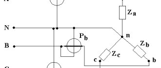
Measurement of active power in three-phase circuits is carried out using three, two or one wattmeters, using various circuits for their connection. The connection diagram of wattmeters for measuring active power is determined by the network diagram (three- or four-wire), the receiver phase connection diagram (star or triangle), the nature of the load (symmetrical or asymmetrical), and the availability of the neutral point.
With an asymmetrical load in a four-wire circuit, active power is measured with three wattmeters (Fig. 3.18), each of which measures the power of one phase - phase power.
The active power of the receiver is determined by the sum of the readings of three wattmeters
Power measurement with three wattmeters is possible under any conditions.
Scope of application of protective grounding
Protective grounding is used in electrical installations with voltages up to 1 kV:
- — in direct current networks with a grounded midpoint of the source;
- — in single-phase AC electrical networks with a grounded terminal;
- - in three-phase AC power networks with a grounded zero (TN - S system; as a rule, these are networks 660/380, 380/220, 220/127 V);
| Protective grounding is designed to protect against possible electric shock. For example, a situation arose when the insulation inside an electrical installation was damaged and the body of the installation (for example, a washing machine or refrigerator) became energized. In this case, a short circuit current occurs to which the protection (machine or plugs) reacts and instantly disconnects the electrical installation from the network. |
The formation of a single-phase short circuit current circuit (i.e. a short circuit between the neutral and phase protective conductors) occurs in the event of a phase wire shorting to a grounded housing of the electrical consumer. The damaged electrical installation is disconnected from the supply network due to the activation of protection caused by single-phase short circuit current.
To quickly disconnect the electrical installation located, circuit breakers and fuses installed to protect against short circuit currents can be used. Also for this purpose, magnetic starters with built-in thermal protection, contactors with thermal relays are used, which provide overload protection, etc.
3.5.1. Ab phase loss
Consider the electrical circuit shown in Fig. 3.20.
Fig.3.20. Electrical diagram of a three-phase delta-connected system with a phase disconnected
When phase ab
current vector
, then expressions (3.14) are transformed into the following form:
,
,
.
(3.16) Figure 3.21 shows a vector diagram of voltages and currents during phase failure a b
load connected by a triangle.
Fig.3.21. Vector diagram of voltages and currents for a delta-connected load with a phase disconnected
3.5.2. Loss of phases ab and bc
Consider the electrical circuit shown in Fig. 3.22.
In case of phase failure ab
and
bc
current vectors
And
, then expressions (3.14) are transformed into the following form:
,
,
.
(3.17) Figure 3.23 shows a vector diagram of voltages and currents during phase failure a b
and
bc
of the delta-connected load.
Fig.3.22. Electrical diagram of a three-phase delta-connected system with two phases disconnected
Fig.3.23. Vector diagram of voltages and currents for a delta-connected load with two phases disconnected
3.5.3. Line wire break
Consider the electrical circuit shown in Fig. 3.24. Let
.
Fig.3.24. Electrical diagram of a three-phase delta-connected system with the line wire disconnected
If the line wire A a
current vector
. Let's transform the circuit in Fig. 3.24 into the circuit in Fig. 3.25.
Fig.3.25. Converting a three-phase delta-connected electrical circuit with the line wire disconnected into a single-phase electrical circuit
From the transformed diagram it follows:
,
,
. (3.18)
According to Kirchhoff's first law:
;
. (3.19)
Using formulas (3.18) and (3.19), we construct a vector diagram:
Fig.3.26. Vector diagram of currents of the converted circuit
Voltage relay connection
The voltage relay is connected according to the diagram below:
Fig.6 Voltage relay connection diagram
This is the standard scheme. Lines with arrows show power circuits.
If you're on the safe side, it's better to use an automatic bypass in the connection diagram, as is done in voltage stabilizers. This is done so that the consumer can at least work if the voltage goes beyond the limits. If necessary. The bypass machine is connected parallel to the internal relay contacts of our voltage relay, in this case to contacts “2” and “3”
A bypass can also be useful if the voltage relay itself fails.