The design and principle of operation of the rack switch of the PBB windings of a power transformer
Hello, dear readers and guests of the Electrician's Notes website.
In the article about the acceptance tests of the TMG11-1600 transformer, I said that switching the branches of the windings of a power transformer is carried out using a PTRL switch.
The voltage steps are regulated manually on the high voltage (HV) side in the range from -5% to +5% (in steps of 2.5%) of the rated voltage 6-10 (kV) without excitation (PWH), i.e. when it is necessary to disconnect the power transformer from the network, both on the high side (HV) and on the low side (LV).
Voltage regulation on the high side (HV) allows the switch design to be simplified due to lower currents compared to the low voltage (LV) winding. In addition, the high voltage winding (HV) has many more turns, which means voltage regulation can be carried out much more accurately.
Basically, tap switches have 3 or 5 regulation stages, the middle position of which always corresponds to the rated voltage.
When carrying out the next acceptance tests for a similar transformer, albeit of slightly lower power (TMZ-630/10U1), we did not pass the obtained values of the ohmic resistance of the HV windings to direct current, i.e. the difference in the measured resistances between the phases was significant and significantly exceeded the standard of 2%, and at all positions of the off-circuit switch.
PUE, Chapter 1.8, clause 1.8.16.4 and PTEEP, Appendix 3, clause 2.5:
RD 34.45-51.300-97 “Scope and Standards for testing electrical equipment”, 6th edition, clause 6.8:
In this regard, it was decided to drain the oil, open the transformer cover and check the contacts in the off-circuit switch. So I decided at the same time to show you the device and principle of operation of the switch, as they say, not in words, but in deeds.
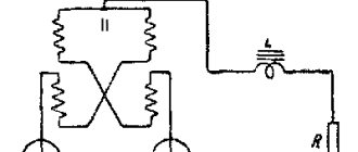
The TMZ-630/10U1 transformer under consideration is equipped with a rack-type PBB switch.
In addition to rack-and-pinion type switches, there are also drum-type switches, but I will tell you about them some other time, when the opportunity arises.
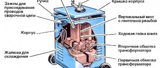
The rack and pinion switch is located inside the transformer (in the oil) directly under the tank cover, and its handle is located outside.
As I said at the beginning of the article, switching of winding taps occurs on the high side (HV).
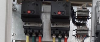
Here are the high-voltage bushings (HV) of the transformer.
And here is their appearance, but with the oil drained inside the transformer tank.
At the same time, I’ll show you the low side (NN).
I was unable to find a drawing of the switch design for our particular transformer TMZ-630/10U1. But I came across a drawing of a similar (similar) PTRL rack switch with 6 pins for each phase.
PTRL stands for:
- P - switch
- T - three-phase
- R - rack and pinion
- L - dial drive
As you can see, the design of the PBB winding rack switch is quite simple. There are 18 pins installed on the lower fixed rail (6 for each phase).
Each terminal is connected to a corresponding branch from the winding, according to the diagram below (“star” without zero - Y).
Above the fixed rail there is a movable rail on which 3 contact jumpers are installed (each phase has its own jumper).
The movable rack is connected to the manual drive shaft, when turning it, it moves with a certain step through the gear segment and closes the corresponding terminals of the winding branches with its contacts (jumpers).
Fixing the position of the switch handle at a certain stage is carried out by a special locking device located on the transformer tank.
Let's return to our problem, due to which the ohmic resistance of the primary windings to direct current had unequal values and went beyond the norm.
According to the operating manual for rack and pinion switches, the springs pressing the movable contact (jumper) should be compressed to 1/3 of the length from their extended state, and the screws compressing the springs should be locked. Apparently, over time of long-term operation, the nuts loosened a little and, accordingly, the contact itself weakened, which gave rise to a spread in the parameters of the ohmic resistance.
As a result, the compression springs and nuts were tightened accordingly, after which all measurements returned to normal.
In addition to the “star” primary winding circuit without zero (Y) presented in the article, there is also a “triangle” circuit (D), the windings of which are switched by a similar rack and pinion switch with 6 pins per phase.
Below are two more diagrams where the windings are also switched using a PTRL rack switch, but with only 5 pins per phase.
Connection diagram of the winding branches according to the star circuit without zero (Y):
Connection diagram of the winding branches according to the “star” circuit with zero (Y0):
Now you can imagine the design of a rack switch and how the transformer windings are switched. If your network voltage has decreased (increased) less (more) than the maximum permissible value, then by switching the stages of the off-circuit switch, you can bring the output voltage of the power transformer to the normalized value.
The principle of operation of the rack-and-pinion tap switch of windings in a transformer is more clearly demonstrated in the video.
Answers to questions about transformers.
During the work of our company, and this, for a minute, is more than 15 years, we have accumulated valuable experience that helps in solving the everyday complex problems of our customers, and which we would like to share with users of our site. Thanks to the “Question-Answer” section, we provide feedback to our clients, and we found some questions interesting. Some questions are asked very often, others not so much, however, in any case, we decided to highlight in this article those points that, of course, are very important in the daily operation of transformers.
So let's start with the questions that are key. We have answered these questions more than once, however, they still concern many of our visitors:
— On what principle is the operation of a transformer based?
Answer: The principle of operation of any transformer is based on the phenomenon of electromagnetic induction. Those. a phenomenon associated with the occurrence of electric current in a closed circuit of a transformer.
- What is an antsapf?
Answer: Antsapf is a so-called PBB switch (abbr., switching without excitation). In a power transformer, such a switch is installed on the high voltage (HV) side and is intended, first of all, to change the transformation ratio. When the highest voltage changes within +- 10% of the rated value, the annulus allows you to maintain the voltage on the secondary winding constant. Switching the position of the tap-changer (an-capf) must be done only when the transformer is turned off (relieving the voltage on the HV side).
— Why is the transformer core made from several insulated plates, and not from a single piece of steel?
Answer: The transformer core is manufactured using insulated laminations to reduce or virtually eliminate losses caused by the flow of eddy currents. Thus, thanks to a core made of insulated plates, the total amount of losses will be several times lower than losses when using a solid core. It is worth noting that the core can be made in one piece, however, a prerequisite is a high resistivity of the material (this could be, for example, ferrite alloys).
— Why are the transformer core plates held together with pins?
Answer: This was done in order to ensure the tightest possible fit of the insulated plates to each other, as well as to make the package of core plates durable and sufficiently resistant to mechanical damage.
— What is no-load operation of a transformer? How does a transformer work in this mode?
Answer: The no-load mode of a transformer is a mode of operation of the transformer in which one of its windings is powered from an alternating current (voltage) source (power line), and the circuits of the remaining windings are open. In reality, this mode of operation occurs in a transformer when it is connected to the network, but the load powered from its secondary winding is not yet connected.
During our time running the “Question and Answer” column, we have more than once had to delve into the intricacies of private problems that arise among users. Often, questions are asked by students, or simply people who have doubts, as, for example, in the following questions:
— What happens on the secondary windings of the transformer if the voltage on the primary winding of the transformer decreases?
Answer: The voltage on the secondary windings of the transformer decreases strictly in proportion to the transformation ratio.
— We own six adjacent plots of land without electricity, however, there is a 380V power line running nearby. For the purpose of powering future buildings, we are going to purchase a step-down transformer. Please tell me which one to choose?
Answer: First, it is necessary to determine the planned total power consumption. Here, one should take into account the possibility of increasing the number of consumers (and, accordingly, increasing consumption). Then send your application to us, and we, based on your information, will select a suitable step-down transformer option.
We are also asked questions that indirectly relate to the choice of transformer. You can call them “questions from the curious.” And although information on such issues can often be found in the public domain, we are happy to accommodate:
— What determines the calibration interval of current transformers?
Answer: The timing of the calibration intervals for transformers is set directly by the manufacturer, based on the characteristics of this particular transformer model. As a rule, the calibration interval of a transformer is 4 years.
— What do the designations of protection windings 5P and 10P on a transformer mean?
Answer: The designations 5P and 10P are used to display the relay protection error of 5% and 10%, respectively.
— Current transformer and operational current transformer - what is the difference?
Answer: The main difference is the purpose of these transformers. Current transformers are designed to convert current to such values that would be convenient for measurement, and, therefore, are used to connect various measuring equipment. The operational current transformer is intended to power various equipment control circuits (relays, drives, etc.), automation, as well as alarm and protection.
— What is the difference between transformers with an isolated neutral and a solidly grounded neutral?
Answer: In transformer circuits with a solidly grounded neutral, the secondary winding is connected according to a “star with a zero terminal” circuit, and therefore such a transformer has 4 terminals. One of the conclusions is zero. At the same time, it is connected to the ground loop. In transformer circuits with an isolated neutral, a “star” connection scheme for the secondary winding is used, which results in 3 terminals. Transformers with a solidly grounded neutral are safer if one of the phases breaks, but with an isolated one, they do not stop the supply of electricity.
Features of the operation of the pbv transformer and decoding
Consumers of electrical energy operate more efficiently at rated voltage. However, this condition is quite difficult for everyone. Acceptable for consumers is its deviation of up to +5%. To achieve a voltage value close to the nominal value, the number of turns of the transformer windings is changed. This can be done in two ways:
- Relationship between voltage regulation and a change in the number of turns. Place of installation of the trunnion.
- Methods of PBB transformer
- Operation and repair of devices
- using a transformer tap-changer device;
- adjusting voltage under load.
What is voltage drop
To put it simply and to make it clearer, this is energy (and active!) released in the form of heat.
Let me give you an example. For each wire cross-section there is a maximum allowable current. If to a copper wire with a cross-section of 2.5 sq. mm connect a single- phase electric body with a power of 9 kW with a current consumption of 9000:220 = 41 amperes, then the wire will get very hot.
The material from which the wire is made, copper, actively resists electric current.
According to Ohm's law, the electric current is directly proportional to changes in voltage, therefore, when an electric boiler is connected to this section of the wire, the voltage also increases and the wire heats up.
Unclear? Let's go into more detail. Let's assume a wire resistance of 1 ohm. The current, as already determined, is 41 amperes.
Then the voltage on the wire will be U=R*I= 41 Volts
This is the voltage drop across the wire. In this case, power will be released in the form of heat P=U*I=41*41=1681 Watt
And this is a whole electric heater with a power of 1.7 kW!!!
Of course, such power dissipation in the wire leads to overheating and melting of the insulation. That is why the current is limited for each section.
In this case, for 2.5 sq. mm, the permissible current is 25-27 amperes.
From all of the above it follows:
As the load increases, the current increases and the voltage drop and energy loss in the wires increases
In other words, some of the voltage and energy simply does not reach our sockets, but is released into the air in the form of heat...
And now the most important thing!
To compensate for such inevitable energy losses, the voltage is increased on the secondary winding of the power transformer.
That is, they increase the voltage above 10,000 Volts - up to 11, or even more kilovolts. Then, even if some of the energy is “lost” in the wires, in our apartments and houses the voltage is within normal limits - about 220 Volts.
Relationship between voltage regulation and changing the number of turns
There are several methods for maintaining the voltage value of consumers within the required limits. Among them, a special place is occupied by the method of its regulation. The advantages of this method are:
- improvement of voltage conditions for consumers;
- increase in permissible voltage loss;
- improving the quality of electricity delivered to consumers.
When designing electrical networks, the means, boundaries and degrees of regulation, the installation location of the regulators, as well as their automation system are selected.
The value of the primary and secondary voltage is directly proportional to the number of turns of the windings in which it flows:
U 1 / U 2 ≈W 1 / W 2,
where U 1, U 2 are the primary and secondary voltages, respectively;
W 1 / W 2 - respectively, the number of turns of the primary and secondary windings
It follows from this that to change the voltage at the transformer output it is necessary to change the number of turns of one of the windings. Thanks to this, the winding that will be involved in switching is made with branches.
Despite the simplicity of the process, there are some difficulties. When switching from one branch to another, under no circumstances should you break the current circuit. At the same time as this requirement, it is prohibited for the switch contacts to close two adjacent branches, otherwise a short circuit of this part of the winding cannot be avoided. And this, in turn, will lead to its damage due to the large currents that arise.
There are two ways to satisfy these conditions: switching the branches of the windings after disconnecting all its windings from the network and during operation, under load.
Basic concepts about pbv transformer
The PBB of the transformer has a very simple decoding, which is contained in the first letters of the words - “switching without excitation”. This means that all switching must be carried out at the transformer, which is disconnected from the power source.
But another name for the PBB transformer device is also widely known - antsapf. An antzapf (switch) is a device with which the number of turns of the winding can be changed to regulate the output voltage.
The switch is designed to change the transformation ratio within 5%, changing the number of turns of the high voltage winding involved in the work.
Place of installation of the antsapf
For transformers that have a multi-layer cylindrical winding with a power of up to 560 kVA, the location of the trunnion is near the zero point.
If the transformer is manufactured with a power of up to 1000 kVA, a voltage of up to 10 kV and has continuous windings, use a reverse circuit with a tap near the zero point.
In transformers over 1000 kVA and 35 kV, a circuit with a control tap in the middle of the winding is used. In this case, the antsapf consists of three elements. They are placed on a common axis, one on top of the other. The switch closes a pair of contacts simultaneously in any phase. This type of switch design is the cheapest and smaller in size.
To keep switching currents low, the trunnion must always be installed in the high-voltage winding. This achieves the production of taps and device switches of more compact dimensions. At the same time, the high-voltage winding has many more turns, which results in higher adjustment accuracy.
When switching the antzapf from one stage to another, turn the switch handle. It is located on the roof of the tank.
When adjusting using the non-excitation method, disconnecting the transformer first from the low voltage side and then from the high voltage side is a prerequisite.
The switch handle drive is covered with a cap. Near the handle indicator there are symbols +5%, “Nom”, -5%. When the handle indicator is turned to indicate +5%, all turns of the winding are activated. When reading “Nom” - 5% less. When set to the designation -5%, there are 10% fewer winding turns in operation.
In some types of transformer, instead of the designations +5%, “Nom”, -5%, the numbers I, II, III are indicated. In this case, reading I corresponds to +5%, II - “Nom”, III - 5%.
If the power of transformers is in the range from 25 to 6300 kVA, then they are designed with branches for manual switching to regulate the voltage within ±5% in steps of 2.5%.
Methods of PBB transformer
Switching a transformer without excitation can be done in two ways:
- Changing the voltage using the primary winding.
- Regulation by installing a trunnion in the secondary winding.
If the voltage change is made using the primary winding, then the trunnion is installed in it. This method finds application only in step-down transformers. This method is also called voltage regulation by changing the magnetic flux.
Despite the loss of voltage in the winding, we can take U 1 ≈ E 1. The electromotive force in the primary winding will not change due to unchanged parameters: frequency and network voltage:
E 1 = 4.44 f W 1 F m
Considering that no changes in frequency are expected during operation, the product W 1 Ф m will not change. Therefore, the magnetic flux can be reduced by connecting more turns of the primary winding. For example, to achieve a voltage drop at the terminals of the secondary winding of 2.5%, it is necessary to increase the number of turns of the primary winding by 2.5%.
Branch terminals of step-down transformers can provide a +10% premium. To do this, you need to connect -5% of turns to them.
For example, depending on the terminal to which the switching device is connected, the surcharge percentage for a 10 kV step-down transformer will change.
| Clamp | Mains voltage, V | Increase, % |
| +5% or I | 10500 | 0 |
| "Nom" or II | 10000 | -5 |
| -5% or III | 9500 | +10 |
The second method is used in step-up transformers. The low voltage winding (primary) is connected to the network.
If the frequency and voltage are constant, the magnetic flux will be stable, and the electromotive force E 2 will change in accordance with the change in the turns of the secondary winding depending on the formula:
E 2 = 4.44 f W 2 F m
The formula indicates that if the number of turns at the terminals of the secondary winding decreases, then the voltage will decrease. Analysis of the formula confirms that the number of turns and the voltage value are directly proportional.
Very often, in step-up transformers, the required number of turns is already connected and taken into account to obtain the highest voltage. Therefore, when operating without load, the step-up transformer will have no extra charge.
Operation and repair of devices
In transformers, 10% of their breakdowns are faults associated with damage to the axle contact system:
- Loose fit of movable and immovable parts of contacts. This occurs due to a decrease in contact pressure, as a result of which an oxide film forms on the surface of the contacts.
- Over time, the junction of the control branches with parts of the switching device weakens.
- Over a long period of operation, the strength of the connection between the control branch and the winding decreases. The main reason is poor soldering.
All these factors lead to heating of the damage site, which can subsequently cause an emergency breakdown of the entire transformer. Therefore, maintenance and repair of antzapf equipment occupy a worthy place among other equipment.
The first operation when repairing a switch device is inspection. Assessing the condition of fixed and moving contacts is necessary, since they are in transformer oil for a long time during operation. Because of this, they are covered with an oxide film. To remove it, you need to thoroughly clean the contacts with a rag that has previously been moistened with purified gasoline. If the contacts are burnt and melted, they are replaced with new ones, which can be purchased or made independently. When making it yourself, an important condition is the selection of materials for contacts that are similar in quality to factory ones.
After replacing the damaged parts, tighten the fasteners, check for the absence of jamming, the correct contact of the moving and fixed contacts, and update the inscriptions near the switch cover.
After completing all the adjustment operations of the trunnion, it is necessary to test the quality of its performance. To do this, switches are made to all stages within ten cycles. There should be no interference in the operation of the device .
The imperfection of all real methods of regulation without excitation is that in order to switch branches it is necessary to disconnect the transformer from the power source. This creates interruptions in the supply of electricity to consumers.
A common method is to regulate voltage under load.
Anzapf device
A transformer trunnion is a simple device in the form of a turn connection, which is associated with a switch and a winding on the high side. The adjustment is made in two directions: upward (decreasing) and downward (adding). All this is characterized by the physical law of Ohm, which assumes a proportional ratio of resistance to voltage level.
To understand the position of the transformer trunnion, you need to look at the nameplate symbols. Each step involves a 2.5% change either down or up. To maintain the stability of the contact resistance, a spring device is used.
Note that over time, the insulation resistance may decrease, so the device must be transferred at least 2 times a year. Once a year, physical measurements of the windings should be carried out using a megger or other insulation service equipment.
Switching without excitation – transformer off-circuit switching
In some cases, it becomes necessary to change the characteristics of the transformer during operation. Let's consider the design features and principle of operation of PBN transformers, the adjustment procedure, range of action and other related issues.
- What is PBB
- Design, principle of operation
- How is the adjustment carried out?
- Classification
- Advantages and disadvantages
- By what percentage can the voltage be adjusted?
- PBB protection
Design, principle of operation
The WSP includes the following elements:
- voter – switch between branches;
- drive mechanism.
Depending on the design and power characteristics of the transformer, the switch can be actuated by a manual or mechanized drive. The mechanized drive provides direct and remote activation.
With a manual drive, switching is done using a handle located outside the unit body.
The following requirements apply to the design of these switches:
- ensuring the proper temperature of contact and current-carrying elements when electric current passes through them;
- ability to withstand the passage of current during a short circuit;
- resource indicator up to 2 thousand switchings;
- reliable insulation.
This device can be installed to change the number of working turns on the input and output coils.
Considering that the output voltage parameters are determined by the number of turns in the output and input windings, the switch changes this characteristic on one of the coils, allowing you to achieve the desired result.
On-load tap-changer and telemechanics: automation of voltage adjustment
Switching the transformer trunnion is an extremely important procedure, especially for substations of 110 kV and above. As noted earlier, the process involves the activation of an on-load tap-changer, the switching of which can be displayed on the dispatcher’s console. For this, telemechanics are used, which can send a signal via a fiber-optic cable to increase or decrease the voltage level.
The general scheme involves the following elements in the chain:
- The presence of a server room that sends and receives signals to the substation, as well as a computer in the control room. The transmission of information involves the use of a conductor, where optical fiber is most often used. Twisted pair cables are also common here, but the information transfer speed is significantly lower.
- At the substation, in the telemechanics cabinet, the cable is connected to a block that interacts with the on-load tap-changer. There are two kinds of raise/lower commands at the output. After the operation, a response is sent to the server, which manifests itself in the execution or non-execution of the task.
- To determine the voltage level, telemetry measurements are displayed on the computer. When adjusting, the latter should change up or down depending on the signal sent.
Automation and telemechanics provide significant comfort in maintaining routine instructions. Building a system largely depends on the technologies and technical means used. It should be noted that building an automated work system is the next step in comfortable regulation of the regime according to the schedule.
How is the adjustment carried out?
The adjustment procedure involves the following operations:
- in the initial position the turns are closed, according to the location of the closing elements of the selector;
- the unit is disconnected from voltage;
- by turning the handle or turning on the mechanized drive, the closing element of the selector moves with a change in the working number of turns on the winding;
- the unit is connected to the network.
Switching is carried out to the required value, according to the required characteristics of the consuming equipment.
How is the voltage regulated?
How can you change the secondary voltage on a step-down transformer? You can change the voltage supplied to the primary winding - then on the secondary it will change in direct proportion.
But this option is not suitable, since transformers connected to the 110 kV network have different loads - some may have 100% load, others may have 20-50% load, etc.
And with this method, the output voltage will change simultaneously for everyone - both where it is necessary and where it is not necessary...
And there are not just a lot of transformers connected, but a lot!
Therefore, another method is used.
The voltage is regulated by changing the transformation ratio of the transformer itself
of the primary changes .
And why in the primary?
In principle, it would be possible to change the coefficient on the secondary winding without any difference; it will still change, since the ratio of turns of the primary to secondary windings will change.
However, it is on the high side that they change - where the voltage is higher. Why?
Everything is very simple. Where the voltage is higher, the electric current is lower.
And since the voltage regulation occurs under load - that is, the transformer is not turned off, then when the turns of the winding change - during switching - an electric arc appears at the point where the contacts switch.
And the higher the current , the larger the arc , and this arc must be extinguished...
By the way, the current values between the primary and secondary windings differ very significantly. For example, on a secondary load, a current of 300 amperes is quite acceptable, and for a primary load the maximum current is 25-30 amperes.
I think there is no need to explain that switching contacts at a current of 300 amperes is much more difficult than at 30, agree)))
Where are these contacts located? In the transformer tank, taps are made from the primary winding to change the transformation ratio and are brought out into a separate compartment, where switching occurs using a special mechanism.
The drive of this mechanism is attached to the outside of the transformer tank, it is called
Classification
Depending on the features of the design device, the following types of switches are distinguished:
- with manual or mechanized drive;
- direct or remote activation;
- single-phase and three-phase;
- drum, equipped with a contact in the form of a ring, segment or lamella;
- rack and pinion
The devices can be intended for use in units of various voltages and currents.
Advantages and disadvantages
PBB is a compact and simple switch, which is the advantage of this device over on-load tap changers that switch the transformer without removing the load.
The disadvantages include the need to completely shut down the unit to make adjustments. But this disadvantage can be neglected if the equipment is powered from two transformers, one of which acts as a backup.
Another disadvantage of the device is the high degree of oxidation of the closing contacts during operation. This feature is a problem if switching is not done very often. Therefore, the device requires periodic maintenance.
The use of PBB allows you to achieve the following positive results:
- improve the energy supply to consumers;
- increase permissible voltage losses;
- improve the quality characteristics of the electrical voltage supplied to the powered equipment.
The simplicity of the design ensures a high degree of reliability of the device.
For normal operation of consumers, it is necessary to maintain a certain voltage level on the substation buses. Electrical networks provide methods for regulating voltage, one of which is changing the transformation ratio of transformers.
It is known that the transformation ratio is defined as the ratio of the primary voltage to the secondary, or
where w1 w2 is the number of turns of the primary and secondary windings, respectively.
Hence U2 = U1w2/w1.
The transformer windings are equipped with additional branches, with the help of which the transformation ratio can be changed. Switching of branches can occur without excitation (PBO), i.e. after disconnecting all windings from the network or under load (on-load tap-changer).
Fig.1. PBV voltage regulation circuit: a - branches near the zero point of the winding ±5% with a three-phase switch for three positions, b - branches in the middle of the winding ±2×2.5% with single-phase switches for five positions (phase A); 1 — fixed contact, 2 — contact segment; 3 - switch shaft, 4 - slip rings
The PBB device allows you to regulate the voltage within ±5%, for which low-power transformers, in addition to the main output, have two branches from the high-voltage winding: +5% and -5% (Fig. 1, a). If the transformer was operating on the main terminal 0 and it is necessary to increase the voltage on the secondary side U2, then by turning off the transformer, switch to the -5% branch, thereby reducing the number of turns w1.
On medium and high power transformers, four branches ±2x2.5% are provided, the switching of which is carried out by special drum-type switches installed separately for each phase (Fig. 1,b). The switch drive handle is located on the transformer cover.
When the switch roller closes contacts A4-A5, the transformer has a rated transformation ratio. Positions A3-A4 and A2-A3 correspond to an increase in the transformation ratio by 2.5 and 5%, and positions A5-A6 and A6-A7 - a decrease by 2.5 and 5%.
The off-circuit switching device does not allow voltage regulation during the day, since this would require frequent shutdown of the transformer for switching, which is practically unacceptable under operating conditions. Typically, tap-changer is used only for seasonal voltage regulation.
On-load control (OLTC) allows you to switch transformer winding taps without breaking the circuit. The on-load tap-changer provides voltage regulation within various limits depending on the power and voltage of the transformer (from ±10 to ±16% in steps of approximately 1.5%).
Fig.2. device for transformers a - circuit diagram for switching on control stages, Ab - main winding, bc - coarse adjustment stage, de - smooth adjustment stages, P - switch, I - selector, b - RNT-13 switching device, 1 - switch, 2 - horizontal shaft, 3 — contactor casing, 4 — vertical shaft, 5 — drive box, 6 — transformer tank
The adjustment steps are performed on the HV side, since a lower current makes the switching device lighter. To expand the control range without increasing the number of branches, coarse and fine adjustment stages are used (Fig. 2). The highest transformation ratio is obtained if switch P is in position II, and selector I is on branch 6. The lowest transformation ratio will be when switch I is in position and selector is on branch 1.
Figure 2,b shows the layout of the elements of the RNT-13 switching device, used on medium-power transformers.
Fig.3. Diagram and switching sequence of an on-load tap-changer with current-limiting resistors
The transition from one branch of the control winding to another is carried out so as not to interrupt the load current and not to short-circuit the turns of this winding. This is achieved in special switching devices with reactors or resistors. A circuit with resistors (Fig. 3) has a number of advantages over a circuit with reactors and is becoming increasingly used. Figure 3 shows the adjusting part of the winding de and the switching device.
The sequence of operation of contactors and voters is shown in the table to Fig. 3. In the initial position 0, the transformer operates on branch 5, the load current passes through contact K1. Let us assume that it is necessary to reduce the number of turns in the control winding, i.e. go to branch 4. The sequence of operation of the on-load tap-changer elements in this case will be as follows: the de-energized selector I2 is switched to position 4, then K1 is turned off and the load current briefly passes through R1 and K2; during the third operation, a short circuit is closed, with half of the load current passing through R1 and K2, and half through R2 and short circuit, in addition, the turns of the control winding 5 - 4 are closed through R1 and R2 and a circulating current of limited value passes through them; during the following operations (4 and 5), K2 opens and K4 closes, while the load current passes through the control winding to branch 4, selector I2, contacts K4 to pin 0.
Switches of this type use powerful springs to ensure fast switching of the contactor contacts (
In modern on-load tap-changers, vacuum arc-extinguishing chambers are used for current switching. Thanks to this, transformer oil is not used as an arc-extinguishing medium and does not require its replacement during operation. RNTA235/1000 switching devices are used on converter transformers with intensive switching operation.
A further improvement of the on-load tap-changer is the use of thyristor switches. Thyristors are triggered when the load current passes through zero and sequentially switch on the required combination of secondary windings.
Fig.4. Voltage regulation circuit in an autotransformer (one phase is shown) a - branches in the neutral (without reverse) b - branches at the linear end of the MV winding (with reverse)
Voltage regulation in autotransformers has some peculiarities. If the branches are made at the neutral point (Fig. 4,a), then this makes it easier to isolate the switching device and design it for a lower current, since a current difference passes through the common winding of the autotransformer. Such regulation is called bound, i.e. when switching branches, the number of turns of HV and MV simultaneously changes. This leads to sudden changes in induction in the core and voltage fluctuations on the LV winding.
Independent regulation in an autotransformer can be achieved using a control winding at the linear end of the medium voltage (Fig. 4, b). In this case, the switching device must be designed for the full rated current, and its insulation must be designed for the full voltage of the middle winding.
Such switching devices for a current of 2000 A with insulation classes of 110 and 220 kV make it possible to provide on-load tap-changers for high-power autotransformers. Regulation is carried out using three single-phase regulators having an electric drive with automatic control.
Fig.5. Scheme for connecting a series control transformer to an autotransformer circuit
To regulate voltage under load on powerful transformers and autotransformers, series regulating transformers are also used (Fig. 5). They consist of a series transformer 2, which introduces an additional EMF into the main winding of the autotransformer 1, and a regulating autotransformer 3, which changes this EMF. With the help of such transformers, you can change not only the voltage (longitudinal regulation) but also its phase (transverse regulation). The design of such transformers is much more complex than the on-load tap-changer, so they are more expensive and their use is limited.
One type of serial control transformers are linear regulators, which are connected in series to a line or to a transformer circuit without an on-load tap-changer, providing voltage regulation within ±10-15%.
Fig.6. Switching on the control transformer from the LV side of the autotransformer
Linear regulators are widely used at substations with autotransformers (Fig. 6). On the MV side, voltage regulation is provided by the on-load tap-changer built into the autotransformer 1, and on the LV side, a regulating transformer 2 is installed, equipped with automatic voltage regulation. Regulating transformers of the LTM type are produced with a power of 1.6-6.3 MBA for a voltage of 6-10 kV, types LTMN, LTDN-16-100 MBA for a voltage of up to 35 kV.
PBB protection
To prevent spontaneous operation of the switch, the device is equipped with a latch that is released when turned on. This element does not allow the tap-changer to switch arbitrarily, thereby preventing emergency situations.
Reliable operation is achieved by regular maintenance. Failure may be due to the following circumstances:
- insufficient tightness of elements;
- loosening of control contacts;
- decrease in the strength of elements during operation due to poor-quality soldering.
As a result, the damaged areas overheat, which can cause the unit to fail. During the maintenance process, the contact points are cleaned of the oxide film that covers the elements over time using a solvent or gasoline.
Upon completion of the service, the device is tested.
The use of PBB allows you to change the characteristics of the voltage supplied by the transformer at the output. This device is much simpler than the on-load tap-changer, but for switching it requires disconnecting the unit from the load.
Transformers with tap switching without excitation (PBB)
With this control method, switching is carried out not only in the absence of current in the switched circuit, but also in the complete absence of voltage on all windings of the transformer, as a result of which this method is called switching without excitation (SWB). For distribution transformers that supply a known “dead-end” load, for example, for electric furnace transformers, it is sufficient to disconnect the transformer from the high-voltage supply network. In other cases, the transformer must be disconnected by external switching devices from all networks connected to it. The off-circuit switch device consists of a selector (tap switch) and a drive. Off-circuit switching devices for general purpose transformers are made with a manual drive, made in the form of a handle, usually located on the transformer cover. This drive is equipped with a device that reliably fixes the tap-changer device in each operating position corresponding to the selected winding branch. The number of such positions is usually no more than 5. The control range usually does not exceed ±5%. To carry out the switching, it is necessary to completely turn off the transformer using substation switches and disconnectors, release the latch (for example, unscrew the fixing bolt or pull back the spring-loaded pin, turn the handle to a new position, and then reinstall the latch.
It is clear that such a switch cannot be carried out frequently. It is used in the following cases: a) Installation of a branch that provides an average voltage level, higher during the period when the loads are higher, and lower when the loads are lower (seasonal regulation). b) In cases where it is necessary to set the transformation ratio in such a way as to obtain a given average level of secondary voltage, at a primary voltage characteristic of a given location where the transformer is installed. It is possible, in particular, that the transformer was selected with a power reserve based on the development of the consumer network. In this case, the voltage can be increased when new loads are connected (“adaptive” regulation). Since the load, and, consequently, the voltage, can change throughout the day, and it is obviously impossible to switch with such a frequency, it is clear that the off-circuit switching device cannot provide built-in voltage regulation even in the simplest cases. PBB of this type is used in distribution transformers of low and medium power, in which it is carried out for switching the windings of the high voltage side (6, 10, less often 20 and 35 kV), as well as for switching on the medium voltage side of powerful high-voltage transformers, whose windings are higher voltages switch under load. PBB is used completely differently in transformers of industrial electrical installations, for example, electric furnaces. In these cases, the tap-changer device is equipped with an electric drive with remote control. The transformer is disconnected from the network during tap switching using a fast-acting and wear-resistant load switch (for example, a vacuum switch). The drive and switch are equipped with electrical interlocks, which exclude the possibility of switching under load and voltage, as well as the possibility of turning on the transformer in the intermediate position of the tap tap selector. The number of positions and adjustment range of such devices can reach, respectively, 12 or more and ±20%. In cases where a short-term loss of power to the consumer is acceptable under the technology conditions, such a technical solution may be preferable to the use of more complex and expensive load switching devices. It is possible to configure the transformer for a given technological mode, for example, for a given type of raw material (charge), as well as operational regulation within this mode. Examples of PCB control circuits for general purpose transformers are shown in Fig. 1. In the diagrams in Fig. 1, a and 1, b, a single movable contact moves along fixed contacts connected to the winding taps, and in the diagram in Fig. 1, the movable contact system is made in the form of a “bridge” connecting the branches of the winding parts. The inclusion and location of the control branches must be such that when part of the winding turns is turned off, there is no significant increase in the transverse magnetic field, causing a decrease in the electrodynamic strength of the winding. This can be achieved in various ways.
Unexcited switching circuits (OPS).
Rice. 2. Examples of PBB devices : a - drum design with ring contacts: 1 - insulating disks, 2-7 - fixed rod contacts, 8 - movable ring contacts, 9 - spring pressure device, 10 - crankshaft; b - rack design: 1 - rack with fixed contacts, 2 - fixed contacts, 3 - rack with movable contacts, 4 - movable contacts, 5 - insulating shaft, 6 - manual drive, 7 - transformer wall.
Rice. 2 gives an idea of the most common designs of tap-changer devices. With a drum design (Fig. 2. a), the fixed contacts are located in a circumferential direction, and with a rack design (Fig. b) - along a straight line. In off-circuit switching devices of electric furnace transformers, more complex circuits and contact systems are often used, for example, separate control windings and corresponding contacts for pipe control (range switching) and fine control (switching within a range).
Voltage regulation of power transformers
02 June 2012 Energy
Greetings, reader of my site!
In this article I want to tell you how the voltage of a 110/10 kV power transformer is regulated under load.
For those who are not at all in the subject, I’ll explain what we’re talking about.
Electricity from a power plant (nuclear power plant, thermal power plant, state district power plant, etc.) is transmitted through overhead line supports many hundreds of kilometers to a substation (I will talk about a 110,000 Volt substation), where step-down transformers are installed - very large and very powerful.
These transformers lower the voltage (in my example to 10,000 Volts) and transmit electricity further, but over a shorter distance - within 10-40 km to the next step-down transformer, which converts the already high voltage of 10 kV into a low three-phase voltage of 400 Volts, which and goes along the wires to our houses.
So, a 110/10 kV transformer installed at a substation is connected to a lot of load - it can be an entire rural area or part of a big city.
The workload changes throughout the day and throughout the seasons and changes greatly.
For example, in winter, many rural residents are heated by electric boilers , so the current consumed is much greater than in summer.
Or there are morning and evening hours of maximum load when people wake up or, on the contrary, come from work, turn on electrical appliances - electricity consumption increases greatly. During the day, the load decreases and sometimes even several times less than in the morning or evening.
Basic technical requirements for tap-changer devices:
A. When the operating current of the control side passes for a long time, the temperature of the contacts and other live parts must be acceptable for the insulation and the environment. When working in transformer oil, the temperature of contact parts without silver coating is allowed to exceed the temperature of this oil by no more than 20 °C. Thus, the requirements for permissible heating of the contacts of these devices are much more stringent than the corresponding requirements for other switching devices, since transformer switching devices operate in hot oil (at temperatures up to 100 ° C). More significant heating of the contacts can lead to deterioration of the condition of the contact surfaces due to contamination with oil decomposition products. B. Devices must withstand the effects of transformer short circuit current (usually 10-20 times the rated current).
B. The wear resistance of PCBs of general purpose transformers must be at least 1-2 thousand switchings, and for PCBs of industrial transformers with electric drives it can reach several hundred thousand switchings.
It should be noted that due to the small number of switching switches of general purpose transformers, their contact systems operate in the same position for a long time, therefore higher demands are placed on the quality of their performance.
D. The insulation requirements of the devices must be sufficient from the point of view of the effects on its insulation gaps when testing the transformer. Therefore, the test voltage values for each of these intervals are established on the basis of calculations of impulse effects or on the basis of impulse measurements of the transformers for which this device is intended.
What happens to a step-down transformer when the load increases
But nothing happens to him))) As he lowered the voltage, he continues to lower it - that’s how he’s designed.
110,000 Volts are supplied to the primary winding (high voltage winding), and 10,000 Volts are removed from the secondary (low voltage winding).
This is an ideal option when the voltage on the primary winding is stable and does not change, and the load on the secondary winding is either very small or nonexistent (the transformer operates in no-load mode).
In fact, this is not true at all.
In reality, the high voltage at the primary load is constantly changing within small limits - 110-117 kV
And since the transformation ratio of the transformer is constant, it turns out that on the 10 kV secondary winding the voltage also fluctuates, so to speak, “in step” with the primary voltage.
And after this, voltage fluctuations are transmitted to the next step-down transformers 10/0.4 kV...
And so these fluctuations will reach our apartments and the voltage would fluctuate in proportion to the high voltage of 110 kV.
And our sockets would have either 180 Volts or 250 Volts, and it would constantly change throughout the day. I think that no one will like it when the light in the house constantly changes brightness, as in that joke - it either goes out, then goes out, or doesn’t come on at all)))