Resonance phenomena are observed in oscillatory systems when the frequency of natural oscillations of the system elements coincides with the frequency of external (forced) oscillatory processes. This statement is also true for circuits with circulating alternating current. In such electrical circuits, under certain conditions, voltage resonance occurs, which affects the current parameters. The phenomenon of resonance in electrical engineering can be beneficial or harmful, depending on the situation in which the process occurs.
Inductance and capacitance reactances
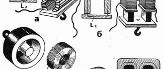
Inductance is the ability of a body to accumulate energy in a magnetic field. It is characterized by a phase lag between the current and the voltage. Typical inductive elements are chokes, coils, transformers, electric motors.
Capacitance refers to elements that accumulate energy using an electric field. Capacitive elements are characterized by a phase lag between voltage and current. Capacitive elements: capacitors, varicaps.
Their main properties are given; the nuances are not taken into account within the scope of this article.
In addition to the listed elements, others also have a certain inductance and capacitance, for example in electrical cables distributed along its length.
Resonance parameters
The value of the amplitude-frequency characteristics can vary within very wide limits. In technology for wireless communications, this type of phenomenon is usually expressed in decibels (dB). Oscillatory circuits can also have amplitude-frequency characteristics. This parameter represents the relationship between the reaction amplitude and the input influence.
Important! The relationship between the phases of oscillations and frequency is usually called the phase-frequency characteristic.
The electrical signal passing through the system can also be accurately detected and recorded. First of all, characteristics such as voltage and frequency are displayed.
Capacitance and inductance in an alternating current circuit
If in direct current circuits capacitance in the general sense represents an open section of the circuit, and inductance is a conductor, then in alternating current circuits capacitors and coils are a reactive analogue of a resistor.
The reactance of the inductor is determined by the formula:
Vector diagram:
Capacitor reactance:
Here w is the angular frequency, f is the frequency in the sinusoidal current circuit, L is the inductance, C is the capacitance.
Vector diagram:
It is worth noting that when calculating reactive elements connected in series, the formula is used:
Please note that the capacitive component is taken with a minus sign. If there is also an active component (resistor) in the circuit, then add it according to the formula of the Pythagorean theorem (based on the vector diagram):
What does reactance depend on? Reactive characteristics depend on the value of capacitance or inductance, as well as on the frequency of the alternating current.
If you look at the formula for the reactive component, you will notice that at certain values of the capacitive or inductive component, their difference will be equal to zero, then only active resistance will remain in the circuit. But these are not all the features of this situation.
The occurrence of resonance in an electrical circuit
Note 1
The occurrence of resonance in an electrical circuit is facilitated by a sharp increase in the amplitude of the stationary natural oscillations of the system, provided that the frequency of the external side of the influence coincides with the corresponding oscillatory resonant frequency of the system.
The $RLC$ circuit represents an electrical circuit with elements (resistor, inductor, capacitor) connected in series or parallel. The name $RLC$ consists of simple symbols for electrical elements: resistance, capacitance, inductance.
The vector diagram of a sequential $RLC$ circuit is presented in one of three variations:
Finished works on a similar topic
Course work Resonance in an electrical circuit 400 ₽ Abstract Resonance in an electrical circuit 220 ₽ Test work Resonance in an electrical circuit 240 ₽
Receive completed work or specialist advice on your educational project Find out the cost
- capacitive;
- active;
- inductive.
In the last variation, voltage resonance occurs under the condition of zero phase shift, and the values of inductive and capacitive reactance coincide.
Voltage resonance
If a capacitor and an inductor are connected in series with the generator, then, provided their reactances are equal, voltage resonance will occur. In this case, the active part Z should be as small as possible.
It is worth noting that inductance and capacitance only have reactive qualities in idealized examples. In real circuits and elements, there is always active resistance of the conductors, although it is extremely small.
At resonance, energy is exchanged between the inductor and the capacitor. In ideal examples, when the energy source (generator) is initially connected, energy is stored in the capacitor (or inductor) and after it is turned off, continuous oscillations occur due to this exchange.
The voltages across the inductance and capacitance are approximately the same, according to Ohm's law:
U=I/X
Where X is Xc capacitive or XL inductive reactance, respectively.
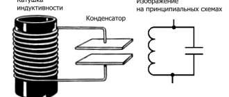
A circuit consisting of inductance and capacitance is called an oscillatory circuit. Its frequency is calculated by the formula:
The period of oscillation is determined by the Thompson formula:
Since reactance depends on frequency, the inductance resistance increases with increasing frequency, while that of the capacitance decreases. When the resistances are equal, the total resistance is greatly reduced, as shown in the graph:
The main characteristics of the circuit are quality factor (Q) and frequency. If we consider the circuit as a four-terminal network, then its transmission coefficient after simple calculations is reduced to the quality factor:
K=Q
And the voltage at the circuit terminals increases in proportion to the transmission coefficient (quality factor) of the circuit.
Uk=Uin*Q
With voltage resonance, the higher the quality factor, the more the voltage on the circuit elements will exceed the voltage of the connected generator. The voltage can increase tens or hundreds of times. This is shown in the graph:
Power losses in the circuit are caused only by the presence of active resistance. Energy is taken from the power source only to maintain oscillations.
The power factor will be equal to:
cosФ=1
This formula shows that losses occur due to active power:
S=P/Cosф
Description of the phenomenon
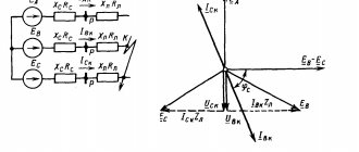
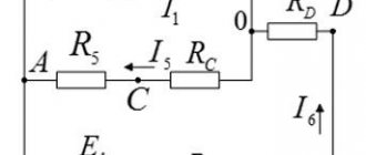
If in a certain electrical circuit (see Fig. 1) there are capacitive and inductive elements that have their own resonant frequencies, then when these frequencies coincide, the amplitude of the oscillations will increase sharply. That is, there is a sharp surge in stress on these elements. This can cause destruction of electrical circuit elements.
Rice. 1. Resonance in an electrical circuit
Let's look at this example to see what phenomena will occur when an alternating current generator is connected to the contacts of the circuit. Note that coils and capacitors have properties that can be compared to the analogue of a reactive resistor. In particular, a choke in an electrical circuit creates inductive reactance. The capacitor causes capacitance.
The inductive element causes a phase shift, characterized by a lag of the current from the voltage by ¼ of a period. Under the action of a capacitor, the current, on the contrary, leads the voltage by ¼ period.
In other words, the effect of inductance is opposite to the effect on the phase shift of capacitance. That is, inductors and capacitive elements influence the generator in different ways and adjust the phase relationships between electric current and voltage in their own way.
Formula
The total reactance of the elements we are considering is equal to the sum of the resistances of each of them. Taking into account the opposite actions, we can write: Xtot = XL - Xc, where XL = ωL is the inductive reactance, the expression Xc = 1/ωC is the capacitive reactance.
Figure 2 shows graphs of the dependence of the circuit impedance and the associated current on the reactance of the inductive element. Pay attention to how the total resistance decreases as the reactance RL (graph b) and how the current increases (graph c).
Rice. 2. Graphs of the dependence of current parameters on the drop in reactance
Electrical circuits consisting of series-connected capacitors, passive resistors and inductors are called series resonant (oscillatory) circuits (see Fig. 2). There are also parallel circuits in which R, L, C elements are connected in parallel (Fig. 3).
Rice. 3. Series oscillatory circuit
Rice. 4. Parallel oscillatory circuit
In resonance mode, the power of the power source will be dissipated only through active resistances (including the active resistance of the coil). Resonant circuits are characterized by losses only of active power, which is spent to maintain the oscillatory process. Reactive power on LC elements is not consumed. The current in the resonant mode takes on the maximum value:
The value of Q is usually called the term “Q factor” of the circuit. This parameter shows how many times the voltage generated at the contacts of the reactive elements exceeds the input voltage U of the electrical network. To describe the ratio of output and input voltages, the coefficient K is often used. At resonance:
K = Uout / Uin = UC0 / U = Q
Formulation
Based on the phenomena described above, we formulate the definition of resonant voltage: “If the total voltage drop across the capacitive-inductive elements is zero and the current amplitude is maximum, then this special state of the system is called voltage resonance.” For a better understanding of the phenomenon, let us rephrase the definition a little: voltage resonance is a state when the voltage on the CL circuit is greater than at the input of the electrical circuit.
The described phenomenon is quite common in electrical engineering. Sometimes they fight it, and sometimes they specially create conditions for the formation of resonance. The main characteristics of any resonant circuit are the quality factor and frequency parameters [ ].
If XL = Xc , the equality is true: ωL = 1/ωC , from here we obtain:
If ω = ω 0, voltage resonance occurs. The frequencies coincide when the inductive reactance is equal to the capacitive reactance of the capacitor. In such cases, only active resistance R will act in the circuit. The presence of reactive elements in the circuit leads to an increase in the total resistance of the circuit (Z):
where R is the total active resistance.
Considering that, according to Ohm's law, U = I/Z , it can be argued that the total voltage in the circuit depends, among other things, on the terms of the inductive and capacitive reactance.
If in the circuit under consideration (Fig. 1) there was no active resistance R , then the value of the total resistance Z would tend to 0. Consequently, the voltage on the reactive elements increases to a critical level.
Since XL and Xc depend on the frequency of the input voltage, for resonance to occur, you must select the appropriate network frequency, or change the parameters of the coil or capacitor until the resonant frequencies coincide. Any violation of the resonance conditions immediately leads to the system exiting the resonant mode with a subsequent voltage drop.
Conditions of attack
Resonance phenomena occur only if the following conditions are present:
- The presence of minimal active resistance in a section of the electrical circuit.
- Equality of reactances arising on the LC chain.
- Coincidence of the input frequency of the power supply with the resonant frequency of the oscillatory circuit.
When there is resonance in the circuit, the voltages on its elements can increase by an order of magnitude or more.
Current resonance
Current resonance is observed in circuits where inductance and capacitance are connected in parallel.
The phenomenon consists of the flow of large currents between the capacitor and the coil, with zero current in the unbranched part of the circuit. This is explained by the fact that when the resonant frequency is reached, the total resistance Z increases. Or in simple terms it sounds like this - at the resonance point the maximum total value of resistance Z is reached, after which one of the resistances increases and the other decreases, depending on whether the frequency increases or decreases. This is clearly shown in the graph:
In general, everything is similar to the previous phenomenon; the conditions for the occurrence of current resonance are as follows:
- The supply frequency is similar to the resonant frequency of the circuit.
- The conductivities of inductance and capacitance for alternating current are equal to BL=Bc, B=1/X.
Resonance - what is it?
Resonance in physics is the frequency-selective response of a system of oscillations to external forces that periodically act on the system. This effect manifests itself in a sharp increase in the amplitude of the movements of these oscillations, when the frequency of the external acting force coincides with some frequencies characteristic of a given oscillatory system.
Important! The essence of resonance is a sharp increase in the amplitude of vibrations when the frequency value of the force acting on the system from the outside coincides with the natural frequency of vibrations of this system.
Dull and sharp resonance
To further talk about the phenomenon of resonance, you should understand what vibrations and frequency are. Oscillations are a process of changing the states of an oscillatory system, which is repeated at certain intervals and occurs around the equilibrium point. An example is swinging on a swing. Resonance of frequencies can occur only where there are oscillatory movements. Moreover, it does not matter at all what type of vibrations are: electrical, sound, mechanical.
Types of oscillatory movements
The oscillation process is characterized by frequency and amplitude. In simple words, using the example of a swing, we can say that the amplitude is the highest point that it reaches. The oscillation frequency is responsible for the speed at which the swing reaches this point.
Returning to the example of a swing, we can say that when it swings, the oscillation system performs forced oscillations. The amplitude of these oscillations can be increased by influencing this system in a certain way. That is, if you push the swing with a certain force and at a certain time, you can swing it strongly without using much effort.
This phenomenon will be called resonance: the frequency of external influences will coincide with the frequency of oscillations in the system, and as a result, the amplitude will increase.
Voltage resonance in an electrical circuit
Application in practice
Let's consider the benefits and harms of resonance of currents and voltages. The resonance phenomenon has brought the greatest benefit to radio transmitting equipment. In simple words, the receiver circuit has a coil and a capacitor connected to the antenna. By changing the inductance (for example, by moving the core) or the capacitance value (for example, with an air variable capacitor), you tune the resonant frequency. As a result, the voltage on the coil increases and the receiver catches a certain radio wave.
These phenomena can cause harm in electrical engineering, for example, on cable lines. The cable represents inductance and capacitance distributed along its length if voltage is applied to the long line in no-load mode (when there is no load connected at the end of the cable opposite the power source). Therefore, there is a danger that an insulation breakdown will occur; to avoid this, a load ballast is connected. Also, a similar situation can lead to failure of electronic components, measuring instruments and other electrical equipment - these are dangerous consequences of this phenomenon.
What is resonance used for?
As a phenomenon, voltage resonance is often used in various electrical type filters. For example, if there is a need to eliminate a certain current component of a certain frequency from the transmission signal, then a coil and a capacitor are connected in parallel to the receiver, which are connected in series with respect to each other. As a result of such actions, an electric current of a certain resonant frequency will close through the inductor-capacitor chain and will not reach the receiver.
Oscillatory circuit
Important! In itself, tension resonance in electricity is a negative phenomenon, since it contributes to the appearance of overvoltages in some areas of the connection and disables devices.