PTK Zapchastenergo LLC produces and sells various windings for oil-immersed power transformers. Windings are usually used as spare parts for the repair of oil power TMs.
The transformer winding is a set of turns that forms an electrical circuit in which an electromotive force is generated, induced in individual turns. The transformer winding contains a winding wire, insulating parts provided by the design; insulation creates the necessary channels for cooling, prevents their displacement under the influence of electromagnetic forces, and protects against electrical breakdown. Transformer windings differ in the number of turns, the type and direction of winding, the number of parallel wires in a turn, and the pattern of connecting individual parts of the winding to each other.
Aluminum and copper wire of rectangular and round sections in accordance with GOST 6324:52, GOST 9761:61 are used for windings of power transformers. Copper and aluminum transformer windings are used for transformers with a power of 20-1000 kVA. Copper, unlike aluminum, is endowed with higher thermal conductivity, greater elasticity, and increased mechanical strength. The tensile strength of copper wires is 3.5 times greater than that of aluminum wires, so it is not recommended to use aluminum windings in high-power transformers.
Since transformers vary in voltage, the windings will also differ. They may differ in the type of winding and its direction, the number of turns and parallel wires, as well as the connection diagram of individual parts into the whole system. To make the winding of an oil transformer, wires with enamel or cotton insulation are used. Power transformers use fiberglass wires, which are resistant to temperature changes.
Based on how the winding is located, the following types are distinguished:
- Concentric. They have a cylindrical shape and are located on a magnetic wire. In this case, the LV (low voltage) and HV (high voltage) windings are located opposite each other. As a rule, the LV winding is located closer to the wire.
- Alternating is the LV and HV winding of the transformer. They change places up the axis of the rod. When the voltage is high, it can be difficult to insulate the windings. That is why they most often resort to the first option.
Cylindrical winding of two layers
The winding principle in this case is the same as in the first option, only the wire is arranged in two layers. Both types should not exceed the number of 4 wires on one turn. This type is used for low voltage (LV). The power of a transformer with a two-layer winding should not exceed more than 550 kilowatts.
Transformer MV
Transformer MV
| Type | Transformers |
| Does gravity work? | No |
| Transparency | No |
| Luminosity | No |
| Explosion resistance | |
| Strength | |
| Tool | |
| Renewable | ? |
| Foldable | Yes (64) |
| Flammable | ? |
| First appearance | ? |
| Text ID | ? |
| Notes When destroying a block with a pickaxe, the main body of the machine falls out. | |
A medium voltage transformer
accepts up to 128 EE/t and delivers 512 EE/t from the “tee” (step-up mode), or up to 512 EE/t from the “tee” and delivers 128 EE/t from any other side (step-down mode).
Receipt
Craft
Recipe up to version 1.96 (game version 1.6.4 and lower). In IC2 Experimental this recipe is relevant again.
(In the game, another, “wrong craft” from one insulated copper wire is possible.)
| Ingredients | Process |
| Machine Main Body + Insulated Copper Wire |
Recipe from version 1.96:
| Ingredients | Process |
| Machine Main Body + Double Insulated Gold Wire |
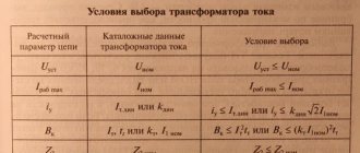
Transformer winding made of aluminum wire (main sizes):
| Winding symbol | Transformer type | Side | Connection diagram | Voltage, kV | Overall dimensions, mm | ||
| Height | Inner diameter | Outer diameter | |||||
| B 4-25-10/0.4 | TM-25/10 | VN | Y/Y0-0 | 10 | 328 | 135 | 199 |
| VN 4-25-10/0.4 | 304 | 150 | 205 | ||||
| VN 4-40-10/0.4 | TM-40/10 | 392 | 160 | 230 | |||
| VN 4-40-10/0.4 | 344 | 160 | 241 | ||||
| VN 4-63-10/0.4 | TM-63/10 | 418 | 160 | 250 | |||
| VN 4-100-10/0.4 | TM-100/10 | 504 | 190 | 266 | |||
| VN 4-160-10/0.4 | TM-160/10 | 492 | 210 | 301 | |||
| VN 4-250-10/0.4 | TM-250/10 | 527 | 235 | 324 | |||
| VN 4-400-10/0.4 | TM-400/10 | 595 | 255 | 355 | |||
| VN 4-630-10/0.4 | TM-630/10 | 629 | 295 | 412 | |||
| NN 4-25-0.4/6-10 | TM-125/10 | NN | 0,4 | 328 | 90 | 127 | |
| NN 4-25-0.4/6-10 | 304 | 96 | 132 | ||||
| NN 4-40-0.4/6-10 | TM-40/10 | 392 | 107 | 146 | |||
| NN 4-40-0.4/6-10 | 344 | 106 | 144 | ||||
| NN 4-63-0.4/6-10 | TM-63/10 | 418 | 118 | 149 | |||
| NN 4-100-0.4/6-10 | TM-100/10 | 504 | 128 | 181 | |||
| NN 4-160-0.4/6-10 | TM-160/10 | 492 | 147 | 201 | |||
| NN 4-250-0.4/6-10 | TM-250/10 | 527 | 163 | 225 | |||
| NN 4-00-0.4/6-10 | TM-400/10 | 595 | 188 | 246 | |||
| NN 4-630-0.4/6-10 | TM-630/10 | 629 | 212 | 285 | |||
| VN 4-25-6/0.4 | TM-25/6 | VN | 6 | 328 | 135 | 199 | |
| VN 4-40-6/0.4 | TM-40/6 | 392 | 160 | 230 | |||
| VN 4-63-6/0.4 | TM-63/6 | 418 | 160 | 252 | |||
| VN 4-100-6/0.4 | TM-100/6 | 504 | 190 | 265 | |||
| VN 4-160-6/0.4 | TM-160/6 | 492 | 210 | 303 | |||
| VN 4-20-6/0.4 | TM-250/6 | 527 | 235 | 319 | |||
| VN 4-400-6/0.4 | TM-400/6 | 595 | 255 | 357 | |||
| VN 4-630-6/0.4 | TM-630/6 | 629 | 295 | 410 | |||
| VN 4-25-10/0.4 | TM-25/10 | VN | 10 | 290 | 145 | 208 | |
| VN S*-25-10/0.4 | 320 | 135 | 194 | ||||
| VN S-25-10/0.4 | 320 | 140 | 205 | ||||
| NN S-25-0.4/10 | NN | 0,4 | 290 | 95 | 135 | ||
| NN S*-25-0.4/10 | 320 | 91 | 124 | ||||
| NN S-25-0.4/10 | 320 | 90 | 130 | ||||
| VN S-40-6/0.4 | TM-40/6 | VN | 6 | 337 | 155 | 230 | |
| VN S-40-10/0.4 | TM-40/10 | 10 | 337 | 159 | 216 | ||
| NN S-40-0.4/6-10 | NN | 0,4 | 337 | 105 | 144 | ||
| VN S-100-10/0.4 | TM-100/10 | VN | 10 | 540 | 160 | 234 | |
| NN S-100-0.4/10 | NN | 0,4 | 540 | 115 | 148 | ||
| VN S-160-10/0.4 | TM-160/10 | VN | 10 | 530 | 203 | 280 | |
| NN S-160-0.4/10 | NN | 0,4 | 530 | 142 | 190 | ||
LV transformer
LV transformer
| Type | Transformers |
| Does gravity work? | No |
| Transparency | No |
| Luminosity | No |
| Explosion resistance | |
| Strength | |
| Tools | |
| Renewable | ? |
| Foldable | Yes (64) |
| Flammable | ? |
| First appearance | ? |
| Text ID | ? |
The low voltage transformer
accepts up to 32 EE/t and delivers 128 EE/t from the tee (step-up mode), or up to 128 UE/t from the tee and delivers 32 UE/t from any other side (step-down mode). If you check the voltage in the wire before and after the transformer, it will be the same 128 eE/t. The difference is that before the transformer there is one flow of 128 eE/t, and after 4x32 eE/t.
Receipt
Craft
| Ingredients | Process |
| Any boards + Coil + Insulated tin wire |
Old version:
| Ingredients | Process |
| Copper ingot + Insulated copper wire + Any boards |
Links and literature
. Rozhkova L.D., Kozulin V.S. Electrical equipment of stations and substations. - M.: Energoatomizdat, 1987. - 315 p. . Neklepaev B.N. Electrical part of power plants and substations. Textbook for universities. 2nd ed. - M.: Energoatomizdat, 1986.-310 p. . Rules for the technical operation of electrical installations. Approved by order of the Ministry of Fuel and Energy of Ukraine dated July 25, 2006. GOST R 52719–2007. Power transformers. General technical conditions. – M.: Standards Publishing House, 2007. – 45 p. . GOST 12.2.007.0–75. System of occupational safety standards. Electrical publication. General safety requirements. – M.: Standards Publishing House, 1975. – 12 p. . GOST 12.2.007.2–75. System of occupational safety standards. Power transformers and electrical reactors. Safety requirements. – M.: Standards Publishing House, 1975. – 5 p.
Transformer SVN
Transformer SVN
| Type | Transformers |
| Does gravity work? | No |
| Transparency | No |
| Luminosity | No |
| Explosion resistance | |
| Strength | |
| Tools | |
| Renewable | ? |
| Foldable | Yes (64) |
| Flammable | ? |
| First appearance | ? |
| Text ID | ? |
The ultra-high voltage transformer
accepts up to 2,048 EU/t and delivers 8,192 EU/t from the tee (step-up mode), or up to 8,192 EU/t from the tee and delivers 2,048 EU/t from any other side (step-down mode ).
Note: if the SVH transformer is switched to step-up mode and a current is passed through it, it will supply 8,192 EU/t, and the maximum voltage when receiving energy in energy storage devices is 512 EU/t (if you connect the transformer in any mode
to any energy storage device, then the energy storage will explode). PS In the experimental version, the maximum voltage when receiving energy in energy storage devices is 2,048 eE/t.
Receipt
6. Safety requirements and environmental protection
General technical conditions for power transformers are given in []. GOST includes technical requirements, safety requirements, including fire safety requirements, environmental protection requirements, operating instructions, transportation and storage. Safety requirements must also comply with [, ]. According to the standard [], grounding of transformer tanks is carried out.
The degree of protection of transformers is determined by the standard []. It states that all transformers, except built-in ones, must be made with protection class 1 or 2 and have a degree of protection of at least IP20. Stationary transformers, in turn, can be manufactured with a degree of protection IP00. The system of standards [] provides requirements for transformer disposal. It describes the following series of actions:
- transformer oil should be drained and sent for regeneration;
- metal components of the transformer must be recycled;
- porcelain insulators, electrical cardboard, rubber seals must be sent to a solid waste landfill.
Power transformers installed in power plants and substations are designed to convert electricity from one voltage to another. Three-phase transformers are most widespread, since losses in them are 12-15% lower, and the consumption of active materials and cost are 20-25% less than in a group of three single-phase transformers of the same total power.
Three-phase transformers for a voltage of 220 kV are manufactured with a capacity of up to 1000 MBA, for 330 kV - 1250 MBA, for 500 kV - 1000 MBA. The maximum unit power of transformers is limited by weight, size, and transportation conditions.
Single-phase transformers are used if it is impossible to manufacture three-phase transformers of the required power or their transportation is difficult. The highest power of a group of single-phase transformers with a voltage of 500 kV is 3x533 MBA, a voltage of 750 kV is 3x417 MBA, and a voltage of 1150 kV is 3x667 MBA.
Fig.1. Schematic diagrams of transformers: a - two-winding, b - three-winding, c - with split low-voltage windings
Based on the number of windings of different voltages per phase, transformers are divided into two-winding and three-winding (Fig. 1, a, b). In addition, windings of the same voltage, usually low, can consist of two or more parallel branches, isolated from each other and from grounded parts. Such transformers are called transformers with split windings (Fig. 1, c). The windings of high, medium and low voltage are usually abbreviated as HV, MV, LV, respectively.
Transformers with split LV windings provide the ability to connect several generators to one step-up transformer. Such enlarged power units make it possible to simplify the design of the 330-500 kV switchgear. Transformers with split LV windings have become widespread in power supply circuits for the auxiliary needs of large thermal power plants with units of 200-1200 MW, as well as at step-down substations in order to limit short-circuit currents.
The main parameters of the transformer include rated power, voltage, current; short circuit voltage; current XX; losses XX and short circuit.
The rated power of a transformer is the value of the total power indicated in the manufacturer's passport, at which the transformer can be continuously loaded under the nominal conditions of the installation site and cooling environment at the rated frequency and voltage.
For general-purpose transformers installed outdoors and having natural oil cooling without blowing and with blowing, the nominal cooling conditions are taken to be the naturally changing temperature of the outside air (for climate version U: average daily no more than 30°C, average annual no more than 20°C) , and for transformers with oil-water cooling, the water temperature at the entrance to the cooler is taken to be no more than 25°C (GOST 11677-85). The rated power for a two-winding transformer is the power of each of its windings. Three-winding transformers can be made with windings of both the same and different power. In the latter case, the highest of the rated powers of the individual windings of the transformer is taken as the rated power.
The rated power of the autotransformer is taken to be the rated power of each of the parties that have an autotransformer connection with each other (“passing power”).
Transformers are installed not only outdoors, but also in closed, unheated rooms with natural ventilation. In this case, the transformers can also be continuously loaded at rated power, but the service life of the transformer is slightly reduced due to worse cooling conditions.
The rated voltages of the windings are the voltages of the primary and secondary windings when the transformer is no-load. For a three-phase transformer, this is its linear (phase-to-phase) voltage. For a single-phase transformer intended to be included in a three-phase group connected in a star, this is V/√3. When the transformer is operating under load and the rated voltage is supplied to the terminals of its primary winding, the voltage on the secondary winding is less than the rated voltage by the amount of voltage loss in the transformer. The transformation ratio of the transformer is determined by the ratio of the rated voltages of the high and low voltage windings:
In three-winding transformers, the transformation ratio of each pair of windings is determined: HV and LV; VN and SN; SN and NN.
The rated currents of a transformer are the values of currents in the windings indicated in the factory passport at which long-term normal operation of the transformer is allowed.
The rated current of any transformer winding is determined by its rated power and rated voltage.
Short circuit voltage uK is the voltage when applied to one of the windings of the transformer while the other winding is short-circuited, a current equal to the rated current passes through it.
The short-circuit voltage is determined by the voltage drop in the transformer; it characterizes the total resistance of the transformer windings.
In three-winding transformers and autotransformers, the short-circuit voltage is determined for any pair of its windings with the third winding open. Thus, the catalogs provide three values of short-circuit voltage: ukV-N, ukV-S, ukS-N.
Since the inductive reactance of the windings is much higher than the active one (for small transformers it is 2-3 times, and for large ones it is 15-20 times), then uk mainly depends on the reactance, i.e. the relative position of the windings, the width of the channel between them, the height of the windings. The value uk is regulated by GOST depending on the voltage and power of the transformers. The greater the higher voltage and power of the transformer, the greater the short-circuit voltage. Thus, a 630 kVA transformer with a higher voltage of 10 kV has uk = 5.5%, with a higher voltage of 35 kV uk = 6.5%; a transformer with a power of 80,000 kVA with a higher voltage of 35 kV has uk = 9%, and with a higher voltage of 110 kV uk = 10.5%.
By increasing the value of uk, it is possible to reduce short-circuit currents on the secondary side of the transformer, but at the same time the consumed reactive power significantly increases and the cost of transformers increases. If a 110 kV, 25 MBA transformer is made with uk=20% instead of 10%, then the calculated costs for it will increase by 15.7%, and the reactive power consumption will double (from 2.5 to 5.0 Mvar).
Three-winding transformers can have two designs in terms of uk value, depending on the relative position of the windings. If the LV winding is located near the magnetic core, the HV winding is located outside, and the MV winding is located between them, then ukV-N has the greatest value, and ukV-S has the lowest value. In this case, voltage losses in relation to the MV terminals will decrease, and the short-circuit current in the LV network will be limited due to the increased value of ukV-N.
If the MV winding is located near the magnetic core, the HV winding is located outside, and the LV winding is located between them, then ukV-C has the greatest value, and ukV-N has the lowest value. The ukS-H value will remain the same in both versions.
The no-load current Ix characterizes active and reactive losses in steel and depends on the magnetic properties of steel, the design and quality of assembly of the magnetic circuit, and magnetic induction. No-load current is expressed as a percentage of the rated current of the transformer. In modern transformers with cold-rolled steel, no-load currents are small.
No-load losses Px and short circuit losses Pk determine the efficiency of the transformer. No-load losses consist of losses in steel due to magnetization reversal and eddy currents. To reduce them, electrical steel with a low carbon content and special additives, cold-rolled steel 0.3 mm thick, grades 3405, 3406, etc. with a heat-resistant insulating coating are used. Reference books and catalogs provide Px values for levels A and B. Level A refers to transformers made of electrical steel with specific losses of no more than 0.9 W/kg, level B - with specific losses of no more than 1.1 W/kg ( at B = 1.5 T, f = 50 Hz).
Short circuit losses consist of losses in the windings when load currents flow through them and additional losses in the windings and structures of the transformer. Additional losses are caused by magnetic stray fields that create eddy currents in the outer turns of the winding and transformer structures (tank walls, yokes, etc.). To reduce them, the windings are made of multi-core transposed wire, and the walls of the tank are shielded with magnetic shunts.
In modern transformer designs, losses are significantly reduced. For example, in a 250,000 kVA transformer, U=110 kV (Px=200 kW, Pk=790 kW), operating all year round (Tmax=6300 h), electricity losses will amount to 0.43% of the electricity passed through the transformer. The lower the power of the transformer, the greater the relative losses in it.
A large number of low and medium power transformers are installed in power system networks, so the total losses of electricity in all transformers in the country are significant and it is very important to improve the design of transformers in order to save electricity in order to further reduce the values of Px and Pk.
Voltage adjustment
For some devices, it is possible to adjust the midpoint, or rather, regulate its voltage. To tune amplifiers, two techniques are used: establishing equilibrium between transistors and setting them to rest.
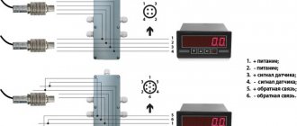
A signaling device for power-type equipment measures the current reduction coefficient when it is grounded, that is, how much current flows into the ground through the use of insulation techniques. The midpoint and filter are responsible for the signal supplied by the regulator. The data is recorded by a voltage meter, which measures the level of voltage reduction observed on the secondary winding, insulating materials and other structural parts of the mechanism.
If a misalignment is observed, then adjustment is carried out to a level acceptable for the class of the device and service life. You can view information and values in tables and operating instructions (the latter do not always contain data).
The technology for obtaining a zero output is actively used. This means that a bridge is made from the midpoint of the vehicle. It turns out two voltages identical in value, identical in direction, but different in phase. Using the manifestation of a phase shift, it is possible to identify problems with the operation of push-pull cascade type amplifiers of medium power.
The midpoint is not displayed unless required by the system. The potentiometer additionally gives balance to the system. Extension cords are used if the outputs of the converters are not matched. Grounding is partially not required if we are talking about low-power equipment options or transformers, rectifiers with average power characteristics.
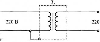
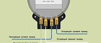
How a single-phase transformer works: basic principles of operation
First, let's clarify what the main components of a single-phase transformer are: a magnetic core consisting of steel plates through which the magnetic flux flows, the primary and secondary windings of the transformer.
It is physically explainable that currents appear and are removed in the first winding due to alternating voltage. Being nearby, the secondary winding catches these currents and converts them into alternating voltage, maintaining the same frequency. The voltage supplied by the unit from the secondary winding depends entirely on the turns that are wound on the primary and secondary windings (coils) present in the transformer.