Basics of radio electronics
First, let's look at an ordinary AA battery. You can read on it that its voltage is 1.5 V. Let's check.
AA battery 1.5 V
To do this, you will need a multimeter, that is, a digital measuring device. First, you should get a cheaper model, always with manual selection of the measurement range.
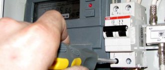
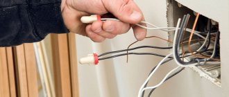
Safety precautions
When working with electrical networks or devices, observe the following rules:
- Before operating or repairing equipment, read the instructions. The safety section specifies unacceptable actions that can lead to short circuits and electric shock.
- The devices must be de-energized. After this, the condition of the wire insulation is assessed. If damage is detected, bare areas are covered with electrical tape.
- If it is impossible to de-energize the electrical network, work in dielectric gloves, shoes with rubber soles and special glasses.
- Access to switchboards and electrical installations is prohibited for novice specialists.
- Do not touch stripped wires with your hands. To find the phase, multimeters, indicator screwdrivers and other tools are used.
Voltage measurement
- connect the black wire to the “COM” connector;
- connect the red wire to the voltage measurement connector “V” (Connecting wires in another way may damage the meter);
- set the knob to the desired division - since we expect to get a value of approximately 1.5 V, then set the knob to a value of 20 in the DCV or V range (the straight line at the letter V means constant voltage);
- The metal tips of the multimeter wires touch the battery poles, but which end goes to which? Try both combinations - the result should be the same, only once it is shown as a "positive" number, in other cases it is preceded by a minus number. This doesn’t matter to us; nothing will happen to the voltmeter either;
- we read the value - in this case, the voltage of the new battery is 1.62 V;
- turn off the multimeter (don’t forget, otherwise the battery will run out).
Measuring the voltage of a 1.5 V battery: a) the red tip of the meter touches the plus of the battery - a positive result; b) the red tip of the meter touches the minus of the battery - a negative result with a minus in front of the numbers.
Attention! When carrying out measurements, in order not to damage the device, we always set the measurement range to a value exceeding the maximum result that we expect to obtain! If we don’t know what to expect, then the safest option is to set the meter to the highest possible range and then reduce it to the most accurate measurement.
Let's check other batteries/accumulators. For the tests we chose: a charged 1.2 V AA size battery - 1.34 V, a partially discharged NiMH battery - 1.25 V.
Now let’s place our 4 batteries in a common housing, the so-called holder. Then insert the ends of the battery assembly wires into the holes of the breadboard as shown in the photo below:
Battery compartment: a) empty, b) with batteries inserted, c) connected to the board
The next step is to prepare jumpers, that is, short wires that will connect the individual components on the breadboard. All you need is a piece of computer cable, wire cutters or a sharp knife.
Computer cable: a) insulated, b) after stripping
First, strip the insulation from the wire. Inside you will find thinner wires twisted together. The next step is to cut a piece of wire to the required length, remove a small, approximately 1 cm piece of insulation from both ends, and you are done. Please note that the wires in the computer cable are thin and break easily and should be handled with care and not bent frequently.
a) pliers, b) wire with stripped insulation, c) ready-made jumpers
If so, you can buy a ready-made set of jumpers. Their big advantage is that you don't have to do it yourself, and they are made from thicker wire that doesn't break as easily.
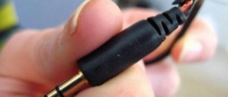
Broken end of the wire
Regardless of which jumpers you choose: handmade or ready-made, we will prepare the contact layer for further work. You will need 4 short jumpers (to connect buses that distribute voltage across the board) and two longer ones, preferably red and blue for power.
Breadboard with jumpers connecting voltage distribution buses
Now let's assemble our first circuit on a breadboard. Take a 22k ohm resistor (red/red/orange/gold stripes). What is its actual resistance? Let's check with a multimeter.
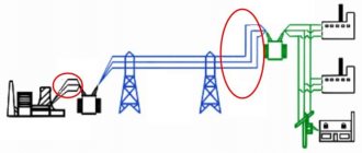
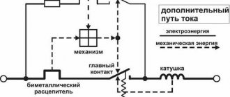
Automatic protection systems
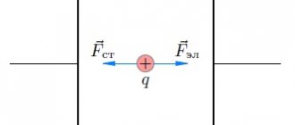
The power grid carries 2 types of threats:
- The power of household wiring is sufficient to ignite materials used in finishing premises. A short circuit in the network leads to an uncontrolled increase in current strength and ignition. It is impossible to reduce the likelihood of such a situation to zero, but it is reduced by introducing a circuit breaker into the circuit. When the current parameters increase, the device plate is deformed, a spring is released, which opens the contacts. The machine does not respond to starting current pulses.
- The neutral wire is connected to the ground, the phase wire is energized in relation to it. A current arises between such a conductor and grounded objects. There is practically no risk of injury to a person by electricity generated between 2 network cables. However, under certain conditions of current flow, electrical injury becomes fatal. Automatic protection systems ensure that current enters one wire and leaves through the other. When voltage appears between the phase and a grounded object, for example, a human body, the RCD de-energizes the network.
Resistance measurement
- connect the black wire to the “COM” connector;
- connect the red wire to the red connector;
- set the switch knob - we expect to get a value of approximately 22 kOhm, so set it to 200 kOhm;
- the metal ends of the multimeter wires touch the resistor terminals (it doesn’t matter which end is which terminal);
- We calculate the value - for this resistor the resistance is 22.1 kOhm;
- turn off the device (don’t forget).
Measure the resistance of the resistor with an ohmmeter
As with batteries, the value measured by the multimeter differs from the rating of the cell being tested. The gold band on the resistor indicates a 5% tolerance.
22 kOhm x 5% = 1.1 kOhm
Therefore, the resistance range for this resistor can be from 20.9 kΩ to 23.1 kΩ. Now let’s connect the plate, the batteries in the holder and the resistor, as in the photo below:
The simplest electronic circuit is connected to a breadboard
In electronics, diagrams are used to illustrate connections between individual elements. In our case it will look like this:
The simplest electrical circuit
The symbol labeled B1 is the batteries providing a total voltage of 4 x 1.5V = 6V. And the 22k ohm resistor is labeled R1. According to Ohm's law:
I = U / RI = 6 V / 22 kOhm I = 6 V / 22000 Ohm I = 0.000273A I = 273 µA
Theoretically, the current in the circuit should be 273 μA. But that the resistance of the resistor can vary within 5%. The voltage provided by the batteries is also not the nominal 6V, and will depend on the battery charge level. Let's look at the actual voltage provided by 4 x 1.5V batteries.
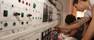
What does electrical engineering study?
Radio engineering for beginners
This science knows almost everything about electricity. It is necessary for anyone who wants to obtain a diploma or qualification as an electrician to study it. In most educational institutions, the course in which everything related to electricity is studied is called “Theoretical Foundations of Electrical Engineering” or, abbreviated as TOE.
This science was developed in the 19th century, when a direct current source was invented, and it became possible to build electrical circuits. Electrical engineering received further development in the process of new discoveries in the field of physics of electromagnetic radiation. In order to master science without problems at the present time, it is necessary to have knowledge not only in the field of physics, but also chemistry and mathematics.
First of all, in the TOE course the basics of electricity are studied, the definition of current is given, its properties, characteristics and areas of application are explored. Next, electromagnetic fields and the possibilities of their practical use are studied. The course usually ends with the study of devices that use electrical energy.
Subject of Study Electrical Engineering
To understand electricity, you don’t have to go to a higher or secondary educational institution; it’s enough to use a self-instruction manual or take video lessons “for dummies.” The knowledge gained is quite enough to deal with wiring, replace a light bulb or hang a chandelier at home. But, if you plan to work professionally with electricity (for example, as an electrician or power engineer), then appropriate education will be mandatory. It allows you to obtain a special permit to work with instruments and devices operating from a current source.
Voltage measurement
- connect the black wire to the “COM” connector;
- connect the red wire to connector “V”;
- set the switch knob - we expect to get a value of about 6 V, so we set the knob to a value of 20 in the DCV or V- range, if necessary, turn on the device, which should show 0;
- use the metal probes of the multimeter wires to touch the wires of the battery holder (depending on which end of which wire we touch, the result will be positive or negative);
- We calculate the value - the voltage of the battery assembly is 6.50 V;
- turn off the power.
Battery Assembly Voltage Measurement
Let's substitute the measured values into the formula obtained from Ohm's law:
I = U / RI = 6.5V / 22.1k Ohm I = 6.5 V / 22100 Ohm I = 0.000294A I = 294 µA
Let's try to check whether we get this result by measuring the current with a multimeter.
Electrical engineering and electromechanics
Electromechanics is a branch of electrical engineering. She studies the principles of operation of devices and equipment that operate from a source of electrical current. By studying the basics of electromechanics, you can learn how to repair various equipment or even design it.
As part of lessons in electromechanics, as a rule, the rules for converting electrical energy into mechanical energy are studied (how an electric motor functions, the principles of operation of any machine, and so on). Reverse processes are also studied, in particular, the principles of operation of transformers and current generators.
Thus, without understanding how electrical circuits are composed, the principles of their functioning and other issues that electrical engineering studies, it is impossible to master electromechanics. On the other hand, electromechanics is a more complex discipline and is of an applied nature, since the results of its study are directly used in the design and repair of machines, equipment and various electrical devices.
Recommendations for beginners
A novice electrician should follow these tips:
- When choosing a cable cross-section, a simple law is taken into account: power is equal to voltage multiplied by current. Using this formula, the main current parameters are calculated. Using tables, the cross-section of conductors and the characteristics of other elements of the electrical network are selected.
- The wires are laid strictly horizontally or at right angles. The distance from the ceiling to the cable must be at least 20 cm. If there are pipes in the room, at least 40 cm away from them.
- Distribution boards are installed at a height of 1.2 m. A distance is left between the individual modules to ensure air circulation.
- Electrical circuits are protected by automatic switches that are triggered when current leaks.
To become an experienced electrician, you need to constantly perform practical tasks and improve your skills.
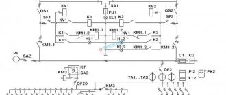
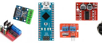
Combined scheme
Let's connect the main power lines and the necessary wiring of the first board.
Let's connect the buttons, LED firmware indicator and piezo buzzer.
Let's connect the capacitors and the seven-segment indicator to the 74ch595 shift register.
Let's connect a seven-segment indicator to a microcontroller.
In the end, your first board will look like this:
The second board, but everything is quite simple here. Let's connect the batteries in series.
Let's put everything together.
Disclaimer
Attention!
This article has many professional inaccuracies, according to respected experts on all issues and part-time commentators, it is also not a guide to action, and can lead to work-related injuries and mental disorders. The author urges you not to use this manual for training and only demonstrates chaotically accumulated knowledge and implements it in the proud pose of a schizophrenic patient with delusional ideas of greatness. Never trust me! I stole your technology!