What could be better than reading about the basics of electrodynamics . That's right, you can find many things that are better. However, we still suggest you read this article. It doesn’t take much time, and useful information will remain in the subconscious. For example, during an exam, under stress, it will be possible to successfully extract Faraday’s law from the depths of memory. Since there are several Faraday laws, let us clarify that here we are talking about Faraday’s law of induction.
Electrodynamics is a branch of physics that studies the electromagnetic field in all its manifestations.
This includes the interaction of electric and magnetic fields, electric current, electromagnetic radiation, and the influence of the field on charged bodies.
Here we do not aim to consider all electrodynamics. God forbid! Let's take a better look at one of its basic laws, which is called Faraday's law of electromagnetic induction .
Michael Faraday (1791-1867)
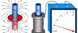
The phenomenon of electromagnetic induction
Electromagnetic induction is the phenomenon of the occurrence of current in a closed conductive circuit when the magnetic flux passing through it changes.
The phenomenon of electromagnetic induction was discovered by M. Faraday.
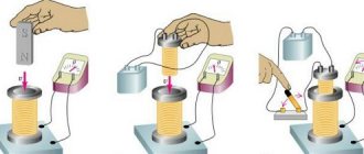
Faraday's experiments
- Two coils were wound on one non-conducting base: the turns of the first coil were located between the turns of the second. The turns of one coil were closed to a galvanometer, and the second was connected to a current source. When the key was closed and current flowed through the second coil, a current pulse arose in the first. When the switch was opened, a current pulse was also observed, but the current through the galvanometer flowed in the opposite direction.
- The first coil was connected to a current source, the second, connected to a galvanometer, moved relative to it. As the coil approached or moved away, the current was recorded.
- The coil is closed to the galvanometer, and the magnet moves - moves in (extends) - relative to the coil.
Experiments have shown that induced current occurs only when the magnetic induction lines change. The direction of the current will be different when the number of lines increases and when they decrease.
The strength of the induction current depends on the rate of change of the magnetic flux. The field itself may change, or the circuit may move in a non-uniform magnetic field.
Explanations of the occurrence of induction current
Current in a circuit can exist when external forces act on free charges. The work done by these forces to move a single positive charge along a closed loop is equal to the emf. This means that when the number of magnetic lines through the surface limited by the contour changes, an emf appears in it, which is called the induced emf.
Electrons in a stationary conductor can only be driven by an electric field. This electric field is generated by a time-varying magnetic field. It is called an eddy electric field . The concept of a vortex electric field was introduced into physics by the great English physicist J. Maxwell in 1861.
Properties of the vortex electric field:
- source – alternating magnetic field;
- detected by the effect on the charge;
- is not potential;
- the field lines are closed.
The work of this field when moving a single positive charge along a closed circuit is equal to the induced emf in a stationary conductor.
The concept of electrolytes
Before talking about Faraday's equation, you should study the properties of substances called electrolytes. The definition in chemistry is simple: these are any compounds whose solution or melt is capable of conducting electric current.
For the existence of directed movement of charges inside any substance, two mandatory conditions must be met:
- The presence of a spatial difference in electric field potentials within a substance. This difference can be created by electrical batteries, for example, inside batteries. The current must be constant, not alternating.
- The existence of free charged particles. If a solution or melt is neutral, then it is formed by both positive (cations) and negative (anions) particles. An important point is their ability to move freely within a substance when a certain potential difference is applied to it.
Electrolytes include solutions of almost all soluble salts (NaCl, K2SO4), acids (HCl, H2SO4) and alkalis (Mg (OH)2, KOH). The case of H2O is curious.
The fact is that distilled (absolutely pure) water does not conduct electricity, however, even a small amount of impurities in it makes it a good conductor. Since it is also an excellent solvent due to the polar structure of its molecules, it is often used to prepare electrolyte solutions.
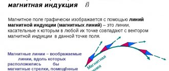
Magnetic flux
Magnetic flux through the area \( S \) of the contour is called a scalar physical quantity equal to the product of the magnitude of the magnetic induction vector \( B \), the surface area \( S \), penetrated by this flux, and the cosine of the angle \ ( \alpha \) between the direction of the magnetic induction vector and the normal vector (perpendicular to the plane of a given surface):
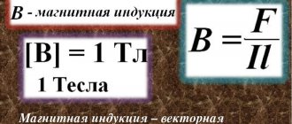
The designation is \( \Phi \), the SI unit is weber (Wb).
A magnetic flux of 1 weber is created by a uniform magnetic field with an induction of 1 T through a surface of 1 m2 located perpendicular to the magnetic induction vector:
Magnetic flux can be visualized as a value proportional to the number of magnetic lines passing through a given area.
Depending on the angle \( \alpha \) the magnetic flux can be positive (\( \alpha \) < 90°) or negative (\( \alpha \) > 90°). If \( \alpha \) = 90°, then the magnetic flux is 0.
You can change the magnetic flux by changing the area of the circuit, the field induction module, or the location of the circuit in the magnetic field (by rotating it).
In the case of a non-uniform magnetic field and a non-flat contour, the magnetic flux is found as the sum of the magnetic fluxes penetrating the area of each of the sections into which a given surface can be divided.
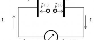
Electrolysis process
To clearly understand the essence of Faraday's laws, one must understand the process for which they are applied. Electrolysis is the decomposition of compounds in their melts or solutions under the influence of a passing electric current. Since we are talking about an electrochemical process, it results in two types of reactions: oxidation and reduction. For their existence, it is necessary to have two electrodes: a cathode and an anode.
Two electrodes
If an electrode is connected to the negative terminal of an electric battery, it will be called a cathode. The second electrode that connects to the positive terminal of the battery is the anode. Both words have ancient Greek roots:
- Catha means "down". Here we mean the movement of electrons in the direction of decreasing the free energy of the system.
- Anas is "up".
Often schoolchildren and students are confused about the charge sign of these electrodes. To eliminate errors, there is a simple memorization method: cations or positive ions of a substance always move towards the cathode, that is, it is a negative electrode. In turn, anions or negative ions are directed by the electric field towards the anion, so it is positive.
There is another way to determine the sign of the electrodes. Since each of them undergoes one of two opposite chemical processes (oxidation or reduction), this fact can be used in this way:
- "Anode" and "oxidation" both start with vowels. Since this process is accompanied by the transfer of electrons to the electrode, it means that the latter is positive.
- “Cathode” and “recovery” both start with a consonant. Since the reduction process is accompanied by the addition of electrons to the ion, this means that the electrode must give them up, that is, it is a carrier of a negative charge.
Redox reactions
It is thanks to them that substances are released or dissolved on the electrodes. The oxidation reaction often results in the formation of gas bubbles at the anode. Reduction processes at the cathode are accompanied by the addition of electrons to cations and the formation of solids from solutions and melts. A few examples should be given for clarity:
- An aqueous solution of table salt (NaCl). If a current is passed through it using carbon electrodes, then Cl- anions will go to the anode (+), where they will be oxidized to atomic chlorine, which will form bubbles of poisonous Cl2 gas. Na+ cations will move and settle on the cathode electrode (-). Receiving from it the missing electrons for the construction of the outer shell, atoms of the alkali metal Na will be formed as a result of the reduction reaction.
- An aqueous solution of copper sulfate CuSO4. Here, the type of reactions that occur will depend on the material from which the anode electrode is made. The reduction reaction at the cathode will lead to the release of copper there, however, different options are possible at the anode. If this electrode is platinum, then oxygen is released and H+ is formed due to the oxidation of H2O molecules, rather than (SO4)2- anions. If the anode is copper, then its own oxidation and dissolution occurs.
The type of specific chemical reaction at the electrodes is determined by the degree of “ease” of its implementation from an energy point of view.
Industrial Applications
Almost all active chemical elements are not found in nature in their pure form. In view of this, the use of electrolysis is a fairly useful method for the production of many metals and gases:
- production of pure aluminum, sodium, potassium and magnesium;
- obtaining concentrated solutions of alkalis and acids;
- hydrogen production, for example, by decomposing water;
- anodizing - coating products with a thin film of various compounds to protect them from corrosion.
Faraday's law of electromagnetic induction
Law of electromagnetic induction (Faraday's law):
The induced emf in a closed loop is equal and opposite in sign to the rate of change of the magnetic flux through the surface bounded by the loop:
The “–” sign in the formula allows you to take into account the direction of the induction current. The induced current in a closed circuit always has such a direction that the magnetic flux of the field created by this current through the surface bounded by the circuit would reduce those changes in the field that caused the appearance of the induced current.
If the circuit consists of \( N \) turns, then the induced emf:
The strength of the induction current in a closed conductive circuit with resistance \( R \):
When a conductor of length \( l \) moves with a speed \( v \) in a constant uniform magnetic field with induction \( \vec{B} \) the emf of electromagnetic induction is equal to:
where \( \alpha \) is the angle between the vectors \( \vec{B} \) and \( \vec{v} \).
The occurrence of induced emf in a conductor moving in a magnetic field is explained by the action of the Lorentz force on free charges in moving conductors. The Lorentz force plays the role of an external force in this case.
A conductor moving in a magnetic field through which an induced current flows experiences magnetic braking. The total work done by the Lorentz force is zero.
The amount of heat in the circuit is released either due to the work of an external force, which maintains the speed of the conductor unchanged, or due to a decrease in the kinetic energy of the conductor.
Important! A change in the magnetic flux penetrating a closed circuit can occur for two reasons:
- the magnetic flux changes due to the movement of the circuit or its parts in a time-constant magnetic field. This is the case when conductors, and with them free charge carriers, move in a magnetic field;
- The second reason for the change in the magnetic flux penetrating the circuit is the change in time of the magnetic field when the circuit is stationary. In this case, the occurrence of induced emf can no longer be explained by the action of the Lorentz force. The phenomenon of electromagnetic induction in stationary conductors, which occurs when the surrounding magnetic field changes, is also described by Faraday's formula.
Thus, the phenomena of induction in moving and stationary conductors proceed in the same way, but the physical reason for the occurrence of induction current turns out to be different in these two cases:
- in the case of moving conductors, the induced emf is due to the Lorentz force;
- in the case of stationary conductors, the induced emf is a consequence of the action on free charges of the vortex electric field that occurs when the magnetic field changes.
Operating principle
The operation of a Faraday cage is based on the fact that when a charge enters a conductor, it is distributed on its surface, while the inside remains neutral. In fact, the entire cell, consisting of conductive material, is a single conductor, the “ends” of which acquire the opposite charge. The resulting electric current creates a field that compensates for the external influence. The electric field strength in the internal part of such a structure is zero.
Interestingly, if the field is generated inside the cell, then the effect also works. However, in this situation, the charge will be distributed over the inner surface of the mesh or other conducting plane and will not be able to penetrate outside.
In English terminology, CF sounds like “Faraday shield”, that is, “Faraday shield/screen”. This concept well conveys the essence of a device that, like a shield or protective screen, reflects the rays affecting its contents.
Lenz's rule
The direction of the induction current is determined by Lenz's rule : the induction current excited in a closed loop when the magnetic flux changes is always directed so that the magnetic field it creates prevents the change in the magnetic flux causing the induction current.
Algorithm for solving problems using Lenz's rule:
- determine the direction of the magnetic induction lines of the external magnetic field;
- find out how magnetic flux changes;
- determine the direction of the magnetic induction lines of the magnetic field of the induced current: if the magnetic flux decreases, then they are co-directed with the lines of the external magnetic field; if the magnetic flux increases, it is opposite to the direction of the magnetic induction lines of the external field;
- according to the gimlet rule, knowing the direction of the induction lines of the magnetic field of the induction current, determine the direction of the induction current.
Lenz's rule has a deep physical meaning - it expresses the law of conservation of energy.
Scientists who made discoveries in the field of electricity
If we asked who discovered electricity, we would get different answers from different countries.
The same thing happens if we ask who created the internal combustion engine, the electric motor, the telegraph, the telephone, the radio, the television, or the computer. This is not surprising, since in some cases the priority of inventions that arose almost simultaneously in different places was the subject of long and complex scientific research, and the final applications often attracted criticism among specialists.
It is unlikely that amber, rubbed with a ball of wool and described by the ancient Greek mathematician and philosopher Thales of Miletus in the 7th century BC. e is recognized as the period of discovery of electricity. Only since the 17th century have there been a number of discoveries in the field of magnetism and electricity.
The discovery of electricity evolved over a long period, allowing different stages to be identified. Scientists who studied electricity provided the application, current structure and performance characteristics of electrical charges today.
Self-induction
Self-induction is the phenomenon of the occurrence of induced emf in a conductor as a result of a change in current in it.
When the current in the coil changes, the magnetic flux created by this current changes. A change in the magnetic flux passing through the coil should cause the appearance of an induced emf in the coil.
In accordance with Lenz's rule, the self-inductive emf prevents the current from increasing when the circuit is turned on and the current from decreasing when the circuit is turned off.
This leads to the fact that when a circuit is closed in which there is a current source with a constant EMF, the current strength is established after some time.
When the source is turned off, the current also does not stop instantly. The self-inductive emf that arises in this case may exceed the source emf.
The phenomenon of self-induction can be observed by assembling an electrical circuit from a coil with high inductance, a resistor, two identical incandescent lamps and a current source. The resistor must have the same electrical resistance as the coil wire.
Experience shows that when the circuit is closed, an electric lamp connected in series with a coil lights up somewhat later than a lamp connected in series with a resistor. The increase in current in the coil circuit during closure is prevented by the self-induction emf, which occurs when the magnetic flux in the coil increases.
When the power source is turned off, both lamps flash. In this case, the current in the circuit is maintained by the self-induction emf that occurs when the magnetic flux in the coil decreases.
Self-inductive emf \( \varepsilon_{is} \), arising in a coil with inductance \( L \), according to the law of electromagnetic induction is equal to:
The self-inductive emf is directly proportional to the inductance of the coil and the rate of change of current in the coil.
Calculation methods
There are several basic ways to determine the inductance of a coil. All formulas that will be used in the calculations can be easily found in reference books or on the Internet. The whole calculation process is quite simple and will not be difficult for people with basic mathematical and physical knowledge.
Through current
This calculation is considered the simplest way to determine the inductance of a coil. The formula through current follows from the term itself. What is the inductance of the coil can be determined by the formula: L=Ф/I, where:
- L - circuit inductance (in Henry);
- F is the magnitude of the magnetic flux, measured in webers;
- I is the current strength in the coil (in amperes).
Finite Length Solenoid
The solenoid is a thin long coil, where the thickness of the winding is significantly less than the diameter. In this case, calculations are carried out using the same formula as through current strength, only the magnitude of the magnetic flux will be determined as follows: Ф=µ0NS/l, where:
Inductance
Electric current passing through a conductor creates a magnetic field around it. The magnetic flux \( \Phi \) through the loop of this conductor is proportional to the induction modulus \( \vec{B} \) of the magnetic field inside the loop, and the magnetic field induction, in turn, is proportional to the current strength in the conductor.
Therefore, the magnetic flux through the loop is directly proportional to the current in the loop:
Inductance is a coefficient of proportionality \( L \) between the current strength \( I \) in the circuit and the magnetic flux \( \Phi \) created by this current:
Inductance depends on the size and shape of the conductor, on the magnetic properties of the environment in which the conductor is located.
The SI unit of inductance is henry (H). The inductance of the circuit is 1 henry if, at a direct current of 1 ampere, the magnetic flux through the circuit is 1 weber:
We can give a second definition of the unit of inductance: an element of an electrical circuit has an inductance of 1 H if, with a uniform change in the current in the circuit by 1 ampere in 1 s, a self-inductive emf of 1 volt occurs in it.
Electric motor
An electrical generator can be run in reverse and become a motor. Consider, for example, a Faraday disk. Suppose a direct current flows through a conducting radial arm from some voltage. Then, according to the Lorentz force law, this moving charge is affected by a force in the magnetic field B, which will rotate the disk in the direction determined by the left-hand rule. In the absence of effects causing dissipative losses such as friction or Joule heat, the disk will rotate at such a speed that dΦB/dt is equal to the voltage causing the current.
Basic formulas of the section “Electromagnetic induction”
Algorithm for solving problems on the topic “Electromagnetic induction”:
1. Carefully read the conditions of the problem. Establish the reasons for the change in the magnetic flux penetrating the circuit.
2. Write down the formula:
- law of electromagnetic induction;
- induced emf in a moving conductor, if the problem considers a progressively moving conductor; If the problem considers an electrical circuit containing a current source and an induced emf arising in one of the sections, caused by the movement of a conductor in a magnetic field, then you first need to determine the magnitude and direction of the induced emf. After this, the problem is solved by analogy with problems for calculating a direct current circuit with several sources.
3. Write down an expression for the change in magnetic flux and substitute it into the formula for the law of electromagnetic induction.
4. Write down all additional conditions mathematically (most often these are the formulas of Ohm’s law for a complete circuit, Ampere force or Lorentz force, formulas of kinematics and dynamics).
5. Solve the resulting system of equations for the desired value.
6. Check the solution.
Electromagnetic oscillations and waves →
← Magnetic field
Electromagnetic induction
3.2 (64.8%) 50 votes
Examples of problem solving
That seems to be all. The significance of Faraday's law is fundamental, because the basis of almost the entire electrical industry is built on the use of this law. To help you understand faster, let’s look at an example of solving a problem using Faraday’s law.
And remember, friends! If a task has stuck like a bone in your throat and you can no longer endure it, contact our authors! Now you know where to order coursework. We will quickly provide a detailed solution and clarify all questions!
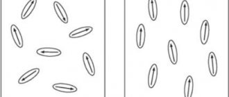
Interaction of a magnet with a circuit
As a clear example of the interaction between a magnet and a circuit, a magnet is placed in a coil made of copper wire. If a magnet is slowly inserted into the coil, the flux created by the magnet across its turns gradually increases. The ordered movement of particles in the coil that appears as a result of such manipulation will be directed clockwise, creating its own magnetic field that weakens the field of the magnet, thereby repelling it from the coil.
If the magnet is moved away from the circuit, its flux decreases, and charged particles begin to move counterclockwise, as a result of which the resulting set of magnetic force lines will attract the magnet.
On a note. In the case of an open (open) circuit: a metal or aluminum ring with a slot; coil, the turns of which are not closed through the ammeter, the power source, this pattern, like Lenz’s rule, does not work.
James Clerk Maxwell mathematically described the basic laws of electricity and magnetism
James Clerk Maxwell
The mathematical formulation of electromagnetic induction was developed by German physicist and mathematician Franz Ernst Neumann (1798-1895) in 1945. These discoveries paved the way for the fundamental theoretical composition carried out by James Clerk Maxwell (1831-1879), starting with Faraday's “lines of force.” However, Maxwell's work was initially distrusted by most physicists and was ignored by engineers.
It was only towards the end of the 19th century, after the memorable experiment with electromagnetic waves conducted by Heinrich Hertz in 1887, that Maxwell's theory became generally accepted and made it possible to turn to both physics and technology.
Electrolysis studies
Faraday's experiments were not limited to the study of magnetic fields. Most of the modern ideas about electrolysis and ions owe their appearance to this English scientist. Faraday reduced an extensive series of experiments to study the behavior of chemical solutions in an electric field to two simple laws that we still use today:
- The mass of substance formed during electrolysis on the electrodes is directly proportional to the product of time and current (i.e., the amount of electricity);
- with the same amount of electricity, the mass of the substance formed on the electrodes is proportional to the chemical equivalent of this substance.
During experiments, Faraday proved that to produce 1.008 kg of hydrogen it is necessary to expend 96,500,000 coulombs of electricity. The same amount of electricity is needed to produce 35.4 kg of chlorine, 63.6/2 kg of copper, 16/2 kg of oxygen. Thus, the measure of electricity required to produce one chemical equivalent of a substance was called the Faraday number.
The enormous contribution that this extraordinary and talented scientist made to physics puts him on a par with Newton, Joule, Einstein and other great people.
First generator
In 1831, the scientist, in order to clearly demonstrate the process of converting mechanical energy into electrical energy, built a Faraday generator. This device had no practical significance, but clearly showed the magic of the creation of electric current.
The Faraday disk was a device resembling a primitive generator. In this design, the magnetic field was directed along the axis of rotation, and the circuit was left motionless. Observers were surprised by the fact that the rotation of the magnet together with the disk led to the appearance of an electromotive force in the stationary circuit. This phenomenon was called Faraday's paradox. This contradiction was resolved after the scientist’s death, when the electron was discovered, which behaves both as a charge and as a particle.
Nicholas Joseph Callan invented the induction coil
Scientists studying electricity took up the idea of the Irish priest Nicholas Joseph Callan (1799-1864) to change the mutually coupled induction.
After his ordination, Callan studied physics at the University of Rome, graduating in 1826. On his return to Ireland he was appointed professor of natural philosophy (what we now call physics) at St. Patrick's College, Maynooth, near Dublin, where he established his laboratory. In 1836, Callan built the first device capable of efficiently exploiting the interconnection of electricity. His device consisted of two coils: with a small number of turns and a large one of well-insulated wires wound on an iron core. An abrupt stop in the current of the first coil caused a high voltage in the second (possibly up to several tens of kilovolts).
In 1854-1855, Callan developed electrochemical cells, which he assembled into large batteries to power electromagnets. Callan also built early electric motors and in 1853 patented a galvanic process aimed at preventing the oxidation of iron. However, he did not neglect his religious calling, writing about 20 books on similar topics. Callan built his device because he needed high voltages in his experiments, transforming them from the low voltage provided by his batteries, but he was unable to put the inventions into widespread use.