Name and terminology in relation to optical sensors
As the name implies, these sensors use optics, which means light radiation of various ranges. That is, a sensor that responds to light. And, of course, some kind of signal indicates that light has been detected. In English terminology, optical sensors are often called PhotoCell Sensor , or Light Sensor , which means photosensor, or light sensor.
In our country, too, in addition to the common “ optical ” one, the same devices are called photosensors , or photoelectric sensors .
The simplest and most common version of such a sensor is a light sensor, which discretely reacts to the level of illumination and issues a signal to turn on the lighting at dusk (main application)
A great variety of photo sensors have been invented, and in my article I will try to popularize and classify this variety.
Using various photo effects
During their operation, » target=»_blank»>photoelectric sensors use three possible photoelectric effects, which depend on how the properties of an object change in the presence of changes in light levels.
- The effects are external when, under the influence of the received light energy, electrons fly out of the cathode of the lamp.
- Intrinsic effects differ in that the resistance of the semiconductor depends on the level of illumination.
- The valve effect occurs when there is a driving force that depends on the lighting.
Operation of optical sensors
Activation. This is the keyword that should be used when describing the operation of any sensors. In our case, activation (or deactivation, but more on that later) occurs when the light entering the sensor input has sufficient intensity.
The operating logic is such that when light enters the sensor unimpeded, it will be activated. And when this light is interrupted by a barrier (a person, a workpiece, a machine part), the sensor is deactivated.
Attention! Don't be confused! Active does not mean at all that its contacts are closed and there is voltage at the output! The operation of the light detection circuit and the output switch may vary! It is possible that the light is interrupted, and this serves as a signal of activity. It all depends on the specific application.
Optical sensors (as well as inductive proximity sensors) are non-contact, that is, there is no mechanical contact with the observed object (activator). Unlike (for example) limit switches and pressure sensors.
In most cases, to increase noise immunity, light is used not from the usual spectrum, but from a laser light source (usually red). Such a source is easy to manufacture; the radiation is easily focused into a thin beam. And due to the fact that the radiation is in the visible part of the range, the position of the sensor is easy to adjust in space.
And here is one of the rare sensors with an ordinary incandescent light bulb, which I found during his lifetime. The emitter is a 6 V incandescent light bulb with a lens. The receiving element is a photodiode. Next is an amplifier and a Schmitt trigger on transistors.
Optical sensor with incandescent bulb and lens. A spot of light is visible below
This sensor is from a 1980 production line purchased with petrodollars from Switzerland.
Modern sensors respond only to “their” part of the spectrum, which allows them to operate accurately in conditions of interference and poor visibility.
Interference may be sunlight or artificial lighting, dust, smoke.
In case of poor care, ordinary dust and dirt can become a hindrance:
Dirty optical sensor, sensitivity adjustment knob on the side, emitting part looking down
On optical sensors, in most cases there is a “Dark On / Light On” switch. What does it mean? It inverts the logic of operation. With “Dark On,” the sensor is activated when no light reaches its input, that is, there is darkness at the input. When light hits, the sensor is deactivated, that is, its output returns to normal. In “Light On” mode, the sensor is activated when its input is illuminated.
There are models where there is a timer - the output signal appears some time after activation (triggering).
Since the sensor contains a threshold element, it needs to be triggered clearly. In this case, the property of hysteresis is used, which reduces bounce (frequent changes in the signal in the “unsteady” zone). To facilitate setup, manufacturers now install in the sensor housing not only an activation indicator, but also an indicator of a stable signal level. If it is lit, it indicates that detection is stable, with sufficient signal strength, and not at the edge of the sensitivity range.
Nuances of installing a light sensor
The light control device is usually mounted close to the luminaire connected to it. For each model, the connection diagram is selected in accordance with the instructions in the data sheet. It is mandatory to study it before starting work.
No special skills are required to perform installation. You just need to calculate everything so that electrical lighting devices do not overload the line. The photo relay puts virtually no load on the network. However, the RCD in the panel and the photosensor itself must be selected based on the number and power of the connected light bulbs.
To install a photo relay yourself, it is enough to have minimal knowledge in the field of electrical installation and follow the simplest safety rules for its implementation.
There are several simple standards for installing photosensitive relays:
- It is recommended to connect the twilight switch and the entire line of lighting devices after it to a separate line from the electrical panel with its own circuit breaker.
- It is strictly forbidden to install the photo sensor upside down. On one side it should be open to sunlight, and on the other side light from artificial lighting lamps should fall on it.
- This electrical appliance must not be installed near flammable materials, near heating equipment or chemically active environments.
- If many light bulbs are connected to the photo relay, then a magnetic starter must be provided in the circuit.
The main thing is that light from any lamps should not fall on the photocell. Otherwise, it will constantly not work as expected. The photo sensor responds to any light. It doesn’t matter whether the lighting is artificial or natural from the sun.
The connection diagram of lighting devices to the photo relay (direct or via a starter) is selected depending on the total power of the connected lamps
On the body of the photo relay there is a plan with a color designation of all the wires coming from it. As a rule, brown goes to the phase from the panel (“L”), blue to zero (“N”), and red or black to the street lighting fixture. You just need to strip the ends of these wires and connect everything in accordance with the attached electrical diagram.
If the photosensor has two contacts, then one of them is connected to the phase from the shield, and the second goes to the lamp. There is no zero in this case.
Image gallery
Photo from
Step 1: Drilling Mounting Holes
Step 2: Stripping the wire insulation for connection
Step 3: Forming Joints by Twisting
Step 4: Checking the functionality of the device
In a situation where street lighting is connected via a magnetic starter, it is connected to a photo relay in the same way as a light bulb. And the lighting devices themselves are powered from it.
In this case, the relay does not close the circuit supplying the lamp, but only the starter. A minimum current passes through the switch in such a circuit, so a cheaper and lower-power device will do. The entire load here is transferred to the external contactor.
How to choose lamps for organizing solar-powered street lighting is described in detail in the following article, which we recommend that you read.
Differences in the way light is transmitted
These are the main differences by which discrete optical sensors are classified. The difference is in the method of “delivery” of light to the input optical element of the sensor.
The most reliable -
With separate receiver and transmitter
Sales managers call such sensors barrier, or beam-intersecting. Although, I think this is incorrect - all discrete sensors work with the beam intersecting with some kind of barrier.
Optical transmitter-receiver type sensor with separate parts
This is the most reliable type of sensor in terms of range and noise immunity. In all other sensors, the transmitter and receiver of radiation are located in the same housing, but in this one they can be separated by tens of meters.
That is, the transmitter is installed in one place, and power is supplied to it. It emits without performing any other functions and without settings. And the receiver is installed at a distance, and sensitivity and other parameters and functions can be adjusted there.
The emitter and receiver must be from the same pair (set), although they can be purchased separately. Transmitters and receivers from different companies do not fit together (but this is not certain).
Such sensors are used in production where long distances need to be monitored. Also - in safety circuits, in security systems and where the air may be polluted (dust, gas).
There is also an option for domestic use - I saw barrier photosensors in an elevator:
Optical sensor in elevator
As long as some clothing or part of the body crosses the path of the sensor beam, no one will go anywhere.
With reflector (reflective)
These sensors combine a source (transmitter) and a radiation receiver in one housing.
Reflex optical sensor with retroreflector
The light is reflected from the reflector and comes back. Therefore, some manufacturers call such sensors retroreflective (reverse reflection).
Optical sensor with reflection from a reflector
By the way, the photo shows the Dark / Light On switch, sensitivity control, and stability and response indicators.
And here is a good photo, the optics of the transmitter and receiver are visible:
Reflex sensor on the optics side, mounted on a bracket
Such a sensor is necessarily a system. For example, a conveyor, and a sensor-reflector system controls the passage of a workpiece:
Reflex sensor on one side of the conveyor
A reflector may also be called a reflector, retroreflector or reflector:
Reflector for optical sensor on the other side of the conveyor
The maximum working distance at which stable operation is ensured is from 5 to 10 m for different models. Theoretically, more is possible, but in practice it is very difficult to ensure stable operation - the slightest shift of the beam due to vibration or weakening of the light due to dust, and that’s all.
The sensor is contaminated with dust, the maximum range in this case drops by about 30%
Reflex type sensors are most often used in production.
Diffuse
This type of sensor is reflective from the object.
Diffuse optical sensor with reflection from the object
It has the shortest range (up to half a meter), but it has an important property - when properly configured, it detects the appearance of objects in the coverage area. After all, you can’t put reflectors on every box or bottle!
The object can be on the axis of action of the sensor, at a distance. As you approach, the sensor, like a threshold element, is triggered.
In the simplest case, there is only one adjustment - sensitivity.
Cool sensors have several buttons or controls, and can be programmed and trained:
Diffuse sensor with training and many settings
IV. Photoresistor.
A photoresistor is a photoelectric device based on the internal photoelectric effect.
Under the influence of radiant energy (visible light, ultraviolet or infrared radiation, X-rays) in a substance, electrons are freed from bonds in the atom and electrons become free, which increase the conductivity of the substance. This type of photoelectric effect is called photoresistive effect.
Photoresistor device:
A photoresistor is a plastic plate on which is applied a thin layer of a semiconductor substance (sulfur or selenium compounds of lead, bismuth or potassium). On both sides of the semiconductor layer, leads are made for connecting the resistor to an electrical circuit, and the layer itself is covered with a transparent layer for protection from moisture and mechanical influences varnish.
In the absence of incident light, the photoresistor is a dielectric. When a photoresistor is illuminated, due to the internal photoelectric effect, the electron concentration in the volume of the photoresistor increases. The resistor becomes a conductor - the resistance decreases in proportion to the incident light flux.
Photoresistors are used in medical devices to measure hemoglobin in the blood, to determine the degree of oxygen saturation of the blood.
Differences in design
It's simple here. If we do not consider sensors of special design (for example, slot-type), then optical sensors can be of two types - in a rectangular and in a cylindrical housing.
I have given enough photos of the rectangular ones, but here are the cylindrical ones:
Optical sensors in a cylindrical housing with a reflector. Control of passage along the conveyor
Sampling points using the sounding method
When selecting a photoelectric sensor for a specific application, there are several points to consider.
When selecting through beam
and
reflective
sensors, please take the following points into account:
Object detection
- Size and shape (length x width x height)
- Transparency (opaque, translucent or transparent)
sensor
- Sensing distance
- Size and shape restrictions (sensor and any reflectors)
- Side by side installation required Number of units
- Mounting step
- The need for staggered installation
- Corner
Environment
- Ambient temperature, humidity
- Presence of splashes of water, chemicals and oil.
If the application requires a diffuse reflective, tunable, or limited distance sensor
, check the specifications;
Object detection
- Size and shape (length x width x height)
- color
- Material (steel, wood, paper, stainless steel, etc.)
- Surface treatment (gloxy, textured, etc.)
- Travel speed
sensor
- Sensing distance
- Size and shape restrictions (sensor and any reflectors)
- Side by side installation required Number of units
- Mounting step
- The need for staggered installation
- Corner
Environment
- Ambient temperature, humidity
- Presence of splashes of water, chemicals and oil.
Connection and types of output signal
This is where the main confusion lies. Sometimes it is difficult to understand what is a Normally Open (NO) and what is a Normally Closed (NC) sensor output. Those who have read my previous articles (links at the beginning) know perfectly well what this is. But in relation to optical sensors it is worth repeating.
Three events need to be linked:
- getting the light of the required intensity,
- turning on the activity indicator
- switching the output element (transistor or relay)
Confusion arises when activity (triggering) is understood as either the hit of light or the hit of an object. And what happens depends on the Dark / Light switch and the type of output - NO or NC.
In NC sensors, the indicator can light up when the contact is closed, or maybe when the sensor is active (These are different events!). Depends on the manufacturer.
I have an article on connecting sensors (link at the beginning), here’s another one. As a rule, the connection diagram is shown on the case:
Connection diagram on the sensor body. Switches, regulators, indicators and terminals - under a sealed translucent cover
In general, you need to carefully read the instructions and check everything in practice.
Types of devices
You can find photoelectric sensors of analog or discrete types.
- With analogues, the output signal can vary in proportion to the available lighting level. Typically, such devices are used to create automatically controlled lighting elements.
- Discrete devices change the value to the diametrically opposite indicator when a certain level of illumination is reached. They can perform all sorts of tasks on an existing production line and are widely used in industry.
An optical non-contact device regulates changes in the incoming light flux in the work area and can operate at a great distance, responding to changes in objects, their absence or presence. The design of this device has two parts that are responsible for proper functioning - a receiver and an emitter. They can be located either in one suitable housing or in different ones.
Specific sensors
Light grid
These are two rulers located exactly opposite. One has LEDs, the other has photodiodes. Thus, by analyzing the overlap of light/photodiode pairs, it is possible to measure the geometric data of the object with some error. For example, the height or width of an object.
Light barrier - ruler for measuring the geometry of objects
The light grid is connected to a specialized controller, which provides data to the main controller.
Light barrier
It is used mainly for security, to keep people or irregularly shaped objects out of the controlled area.
For security, read my article on the blog. And also in the magazine Electrotechnical Market.
A couple of photos to make it clear what we're talking about:
Safety barrier – only what is needed passes through the conveyor, and only when needed!
Barrier in a sensor system
This is a rather complex system, which also includes at least 2 reflex sensors (4 in the photo) and its own controller.
Laser
These are optical sensors that have the ability to measure the distance to an object.
Laser optical sensor
Laser optical sensor with distance display
Laser optical sensor with distance measurement
The principle of operation is to measure the transit time of the beam. Like in radar.
Slot sensors
A separate type of sensors with a receiver and transmitter are slot sensors (fork-shaped). They are convenient because although the transmitter and receiver are separated, they are actually located in the same housing, the design of which has a slot.
Slit optical sensors. Two sensors, one ring with slots.
When an activator (object) gets into the gap between the emitter and the receiver, the sensor is triggered. Slot sensors are useful where the object whose movement is detected has a small, fixed thickness. This design is very similar to the operating principle of an incremental encoder.
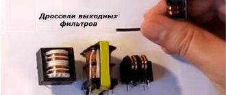
Fiber optic, or fiber optic
I have come across such sensors in a diffuse design, and with a receiver + transmitter.
The idea is that the optical elements and electronic circuit are separated in space, and the light is transmitted through optical fiber (plastic fiber).
Fiber Optic Sensor Element
Do you see the red dot? This is the output of the fiber optic sensor.
At a distance of 4 meters there are the following blocks of fiber optic amplifiers (for three sensors):
Fiber Optic Amplifiers for Sensors
Such a system is installed where there is very cramped space (how to set it up?) and where electronics do not like to work - vibration, humidity, and a high risk of damage.
A few more photos of sensors with fiber optic cable:
Two transceivers with fiber optic wires to the electronic unit. Do you see any abrasions? These are traces from inductive sensors that constantly broke due to imperfect mechanics...
Electronic unit (fiber optic amplifier)
Optical part of the fiber optic sensor. Even taking a photo is problematic, let alone setting it up!
Electronic units – fiber optic amplifiers for fiber optic sensors in the photo above.
Expert of the LAN-ART company on optical transmitters - Berezkin E.N.
A specialist, an expert at the LAN-ART company on optical transmitters, Evgeniy Nikolaevich Berezkin, comments: “Today in every modern home there are optical receivers and transmitters operating via fiber optics. The optical transmitter of cable television networks (CTV) is used to generate an optical signal modulated by an electrical television signal with a group TV signal frequency range of 47 ... 862 MHz. Such transmitters use lasers, and photodiodes are used in receivers. The system uses optical radiation with a wavelength of 1100-1600 nm. “
Analog
These sensors are analog based on the type of output signal. The principle of operation can be similar to that of a laser, or the intensity of the reflected signal is simply measured.
Analog sensor
In this case, an analog signal corresponding to the distance to the surface of the unwinding coil is fed to the analog input of the controller (ADC). And the controller calculates the diameter of the coil.
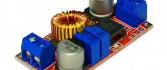
An optical sensor that measures the distance to an object. The red dot on the right shows the measurement location. The sensor housing is protected from impacts by a fastening element
The same sensor is shown at the very beginning of the article. It also has a discrete output that can be programmed to trigger at a certain distance.
Optical flame sensor
This sensor stands apart - it perceives light from the flame of burning gas or other fuel. Used in industrial boiler rooms where increased safety is needed.
I remembered. My article is about modernizing a boiler room, where I installed soft starters instead of contactors.
Here is the model:
Flame sensor for boiler room with discrete output
Or this:
Flame sensor from gas combustion
The principle of operation is similar to that of a radio tube.
Hey, does anyone else remember that there were analog TVs with radio tubes?! An article about how I turned on an old tube TV.
Photoelectric converters
Operating principle and main types
Photoelectric converters are those that change their electrical characteristics under the influence of a luminous flux that is functionally related to the non-electric quantity being measured. The operating principle of photoelectric converters (photocells) is based on the phenomenon of the photoelectric effect, discovered by the Russian scientist A.G. Stoletov in 1888.
The photoelectric effect is carried out in three different ways, and therefore there are three types of manifestation of the photoelectric effect: external, internal and valve. The most widely used converters are the last two types.
Converters with an external photoelectric effect include vacuum and gas-filled photocells and photomultipliers. Vacuum photocells consist of an evacuated glass bulb containing two electrodes: an anode and a cathode. When the photocathode is illuminated under the influence of photons of light, it emits electrons. If a voltage is applied between the anode and the photocathode, then these electrons form an electric current, since it is caused by photons, it is called photocurrent. For photoemission of electrons, it is necessary that the photon energy E = vh, where v is the frequency of light; h – Planck’s constant, was greater than the electron work function Ф, characteristic of a given photocathode material. The frequency vgr=Ф/h is called the red limit of the photoelectric effect, and its corresponding wavelength lgr=s/vgr, where c is the speed of light, vgr is the long-wave threshold of the photoelectric effect. If l>lgr, then no light intensity can cause the photoelectric effect.
A gas-filled photocell is similar to a vacuum one, but has a certain gas filling. Due to gas ionization, the photoemission current increases. The sensitivity of gas-filled photoelectric converters is higher than that of vacuum ones. A photomultiplier tube (PMT) is a vacuum photocell equipped with a system of electrodes to amplify the photoemission current. The schematic diagram of the photomultiplier is shown in Fig. 5.76.
| Rice. 5.76. Photomultiplier tube |
Light falls on the photocathode K, which emits electrons. The flow of electrons is focused by the electric field created by the electrode E, is formed and directed to the accelerating electrode - dynode E1. The voltage across the dynode is such that the photoelectron energy is sufficient for secondary electron emission. The operating mode is such that during secondary emission more electrons are emitted than are incident on the dynode. This is how the flow of electrons increases. The electron flow, amplified by dynode E1, is directed to the following dynodes E2–E5, amplified and collected by anode A. The anode current of the PMT is quite small and requires additional amplification. To do this, it is converted into voltage using a load resistance. The PMT is powered using a voltage divider. Photomultiplier tubes have high sensitivity and are used to measure very low light fluxes (up to 10–5 lux).
The sensitive element of converters with an internal photoelectric effect (photoresistors) is made in the form of a plate on which a layer of semiconductor photosensitive material (cadmium sulfide, cadmium selenide or lead sulfide) is applied. The electrical conductivity of semiconductor materials is due to the excitation of electrons in the valence band and impurity levels. When excited, electrons move into the conduction band; holes appear in the valence band. When illuminated, the excitation of electrons increases, which causes an increase in electrical conductivity. The red border of photoresistors is in the infrared region, for example, for lead sulphide wavelength lgr = 2.7 µm. At low illumination of the converter, the number of electrons excited by light is proportional to the illumination, its electrical conductivity:
G=Iph/U,
where Iph – photocurrent; U is the voltage applied to the converter, also proportional to the illumination.
At high illumination, proportionality is violated. The sensitivity of photoresistors is determined by the factor of change in their resistance. For some types it reaches the value
K=Rt/R200=105,
where Rt is the dark resistance, i.e. the resistance of the unlit converter; R200 – resistance at E = 200 lx. The current-voltage characteristic of photoresistors is linear, i.e. their resistance does not depend on the applied voltage. Inertia is characterized by a time constant t. For sulfur-cadmium converters t lies in the range of 1–140 ms, for selenium-cadmium converters it is 0.5–20 ms.
Rice. 5.77. Typical photoresistor connection circuit
A typical photoresistor connection circuit is shown in Fig. 5.77, which is characterized by high sensitivity. However, the resistance of a photoresistor depends on temperature, similar to the resistance of thermistors. To reduce the temperature error, they are included in adjacent bridge arms.
Rice. 5.78. Semiconductor photodiode design
Photovoltaic converters are photoelectronic devices with a pn junction: photodiodes and phototransistors. When the transition is illuminated, an additional concentration of carriers is created in n-layer 3 (Fig. 5.78). This leads to an increase in their diffusion to the p-n junction and in the junction itself between layers 2 and 3. For a diode connected through electrodes 1 and 4 to the blocking voltage, the reverse current increases under the influence of light. In the absence of lighting, it does not differ from the characteristics of a conventional diode, and when illuminated, it shifts upward in proportion to the magnitude of the luminous flux.
The most common are germanium and silicon photodiodes. Their spectral characteristics extend into the region of infrared radiation (for germanium photodiodes up to lgr = 2 µm, for silicon photodiodes up to lcr = 1.2 µm).
Rice. 5.79. Typical photodiode connection circuits
Photodiodes can operate in photodiode and generator (valve) modes. In photodiode mode, the converter is connected to the blocking voltage (Fig. 5.79, a). As its illumination increases, the reverse current increases, which leads to an increase in the voltage Un across the resistance Rн. Voltage U and sensitivity can be determined by the current-voltage characteristic and the load straight line (Fig. 5.79, b). The dependence of the photodiode current on illumination is almost linear. The internal differential resistance of a photodiode is on the order of megaohms, so they usually operate in a near-short circuit mode.
The total photodiode current I can be considered as the sum I=It+Iph=It+SF,
where It is the dark photocurrent; Iph – photocurrent determined by luminous flux Ф; S – sensitivity.
The value of dark current I strongly depends on temperature. Photodiodes are low-inertia converters. Their time constant is on the order of 10-7–10-8 s.
In generator mode, the photodiode is switched on according to the circuit shown in Fig. 5.79, in, and he himself is a source of current. The photocurrent, load voltage Un and sensitivity can be determined from the current-voltage characteristic.
Photoelectric converters used to measure non-light quantities have a number of features. It is possible to measure without contact with the measurement object, there is no mechanical impact on the measurement object. Converters are sensitive to light intensity and color. Their disadvantage is a large error, which is mainly determined by fatigue, aging and the dependence of the converter parameters on temperature. Due to these features, photoelectric converters are used mainly in the following cases.
1. For measurements in which the converter operates in relay mode. An example is measuring the rotation speed of a shaft having a disk with holes. The disk interrupts the beam of light falling on the photoelectric converter. The measured speed is converted into the frequency of electrical impulses.
2. As a direct converter in compensation measuring instruments.
3. When measuring non-light quantities, when the intermediate conversion quantity is the light quantity, for example, when measuring the concentration of a substance in a solution, when the intermediate quantity is the change in the absorption of light by the solution.
To reduce the measurement error, photoelectric converters are included in differential or compensation measuring circuits.
Optoelectronic elements. According to the degree of complexity of the structural diagram, two groups of devices are distinguished among optocoupler products. An elementary optocoupler (optocoupler) is an optoelectronic semiconductor device consisting of emitting and photoreceiving elements, between which there is an optical connection that provides electrical isolation between the input and output. The principle of operation of optocouplers is based on the following (Fig. 5.80). In the emitter 1, the energy of the electrical signal is converted into light, focused by the reflector 2 on the photodetector 3, where the light signal causes an electrical response.
Rice. 5.80. Implementation principle of the optocoupler
An optoelectronic integrated circuit is a microcircuit consisting of one or more optocouplers and one or more matching or amplifying devices electrically connected to them. Thus, in an electronic circuit, such a device performs the function of a communication element, in which, at the same time, electrical (galvanic) isolation of the input and output is carried out.
Optocouplers can be implemented with a photoresistor, photodiode and photothyristor.
The advantages of these devices are based on the general optoelectronic principle of using electrically neutral photons to transfer information. The main ones are the following:
— the ability to provide ideal electrical (galvanic) isolation between input and output;
— for optocouplers there are no fundamental physical or design restrictions on achieving arbitrarily high voltages and decoupling resistances and arbitrarily small throughput capacitance;
— the possibility of implementing contactless optical control of electronic objects and the resulting diversity and flexibility of design solutions for control circuits;
— unidirectional propagation of information along the optical channel, absence of feedback to the emitter;
— wide, without limitation from low frequencies, frequency bandwidth of the optocoupler, the ability to transmit both a pulse signal and a constant component through the optocoupler circuit;
— the ability to control the output signal of the optocoupler by influencing (including non-electrical) the material of the optical channel and the resulting possibility of creating a variety of sensors, as well as a variety of devices for transmitting information;
— the possibility of creating functional microelectronic devices with photodetectors, the characteristics of which, when illuminated, change according to a complex given law;
— immunity of optical communication channels to the effects of electromagnetic fields, which in the case of “long” optocouplers (with an extended fiber-optic light guide between the emitter and receiver) makes them protected from interference and information leakage, and also eliminates mutual interference;
— physical, design and technological compatibility with other semiconductor and microelectronic devices.
Optocouplers also have certain disadvantages:
— significant power consumption due to the need for double energy conversion (electricity - light - electricity) and the low efficiency of these transitions;
— increased sensitivity of parameters and characteristics to the effects of elevated temperature and penetrating nuclear radiation;
— more or less noticeable temporary degradation (deterioration) of parameters;
-relatively high level of intrinsic noise due to the peculiarities of the physics of LEDs;
— the complexity of implementing feedback, caused by the electrical isolation of the input and output circuits;
— design and technological imperfection associated with the use of hybrid non-planar technology (with the need to combine several individual crystals from different semiconductors located in different planes in one device).
Connection diagram. As a communication element, an optocoupler is characterized by the transmission coefficient Ki, determined by the ratio of the output and input signals, and the maximum information transmission speed F. In practice, instead of F, the rise and fall durations of the transmitted pulses tnar(sp) or the cutoff frequency are measured. The capabilities of an optocoupler as an element of galvanic isolation are characterized by the maximum voltage and decoupling resistance Uin and Rin and the feed-through capacitance Cin.
Figure 5.81. Generalized block diagram of an optocoupler
In the block diagram of Fig. 5.81 the input device is used to optimize the operating mode of the emitter (for example, biasing the LED to the linear section of the watt-ampere characteristic) and converting (amplifying) the external signal. The input unit must have high conversion efficiency, high speed, a wide dynamic range of permissible input currents (for linear systems), and a low value of the “threshold” input current, which ensures reliable transmission of information through the circuit.
The purpose of the optical medium is to transfer the energy of the optical signal from the emitter to the photodetector, and also, in many cases, to ensure the mechanical integrity of the structure.
The fundamental possibility of controlling the optical properties of the medium, for example, by using electro-optical or magneto-optical effects, is reflected by introducing a control device into the circuit. In this case, an optocoupler with a controlled optical channel is obtained, which is functionally different from a “conventional” optocoupler: the output signal can be changed either by the input , and along the control circuit.
In the photodetector, the information signal is “restored” from optical to electrical; At the same time, they strive to have high sensitivity and high performance.
The output device is designed to amplify the signal, since the losses after double conversion are significant, to convert the photodetector signal into a standard form convenient for influencing the cascades following the optocoupler. Often the amplification function is performed by the photodetector itself (phototransistor).
General block diagram of Fig. 5.81 is implemented in each specific device only by a part of the blocks. A real optocoupler can be more complex than the circuit in Fig. 5.81; Each of these blocks may include not one, but several identical or similar elements connected electrically and optically, but this does not significantly change the fundamentals of the physics and electronics of the optocoupler.
Areas of application. As elements of galvanic isolation, optocouplers are used: for connecting equipment units between which there is a significant potential difference; to protect the input circuits of measuring devices from interference and interference.
Another important area of application for optocouplers is optical, non-contact control of high-current and high-voltage circuits. Launch of powerful thyristors, triacs, control of electromechanical relay devices
The ability to change the properties of an optical channel under various external influences on it makes it possible to create optocoupler sensors for humidity and gas contamination, a sensor for the presence of a particular liquid in a volume, sensors for the cleanliness of the surface treatment of an object, the speed of its movement, etc.
The creation of optocouplers with photoresistors, the properties of which change when illuminated according to a given complex law, makes it possible to simulate mathematical functions, and is a step towards the creation of functional optoelectronics.
The versatility of optocouplers as elements of galvanic isolation and contactless control, the diversity and uniqueness of many other functions are the reason that the areas of application of these devices have become computer technology, automation, automated control systems, measuring technology, control and regulation systems.
Malfunctions and care of optical sensors
Just like the optics of SLR cameras, they need to be cleaned, carefully wiped and checked for mechanical integrity.
To clean optics, I use wipes soaked in water with the addition of a small amount of neutral detergent. For example, for dishes. Then I wipe it with a dry cloth. The main thing is that no abrasive gets in.
Another feature. In optical sensors, the emitting element is usually an LED. It has its own service life, and over time the intensity of its radiation decreases. Therefore, it is not surprising that once every few years it is necessary to adjust the sensitivity of the sensors, such is the problem...
Typical photo relay malfunctions
Failures in the use of photo relays are most often caused by their incorrect selection and/or operation. The most common failures are exceeding the resource, but a number of other reasons can be listed:
- Exceeding the permissible current and/or voltage.
- Failures related to cycle time (especially when the relay switches at very low signal levels or when the relay does not operate very often, causing the contacts to oxidize).
- Contamination of the working surface of photo sensors (especially typical for photo relays that serve industrial equipment).
- Poor ventilation of relay panels, which causes overheating of MOSFET transistors.
With proper routine maintenance, all of these problems can be prevented. The service life of the relay and its rated power are always indicated by the manufacturer. These parameters are determined for photorelay operation under low level switching conditions and correspond to the minimum number of operations that can be expected without mechanical failure due to contact wear.
It is much more informative when the developer indicates in the operating instructions the service life of the relay under conditions of hot load switching, when the current and voltage values are maximum (at the rated power of the device). In these cases, the relay fails due to contamination of the contact material, when current and voltage have to be increased to operate: this is accompanied by a sharp increase in resistance during the passage of the control signal. Therefore, light-receiving surfaces should be cleaned as often as possible, using chemically neutral cleaners for these purposes.
When used intensively, photorelay sensors never operate longer than indicated in their technical specifications. Even in low-signal applications, faults in the testing devices can cause device failures. As a result, inrush currents caused by capacitive loads, hot switching and voltage surges accelerate their aging.
Download the book about sensors
• Aleinikov A.F. Gridchin V.A. Tsapenko M.P. Sensors / Aleinikov A.F. Gridchin V.A. Tsapenko M.P. Sensors All types of sensors are considered - theory and practice, pdf, 13.21 MB, downloaded: 2672 times. / • Encoder: a must-have for a production line / Article in the magazine “Electrical Technical Market” from SamElectric.ru.
Varieties and examples of real-life applications of encoders. Descriptions of real equipment components in which encoders are used are given, pdf, 1.15 MB, downloaded: 888 times. / Everything did not fit into the article, there are many more photos and interesting stories about optical sensors, but the article is not rubber)))
Therefore, ask questions and share your experience and photos in the comments, I will be glad!
I will also be glad to increase the number of subscribers and activity in my VK group! Come in, there is the most up-to-date information, which sometimes does not even appear on the blog.
I’m also waiting for new readers and subscribers on my Yandex.Zen . By the way, here is an interesting article on the topic on Zen - varieties and examples of real-life use of encoders. Descriptions of real equipment components in which encoders are used are given.
Adjusting the sensitivity of the photoelectric sensor
Adjusting the sensitivity of photoelectric sensors is very simple. Some sensors consist of a special button called a "learn" button, while others have a potentiometer that can be turned with a screwdriver. A typical photoelectric sensor has two LEDs: green to indicate power and orange to indicate the current output status.
To adjust the sensitivity of the potentiometer type, turn the potentiometer fully counterclockwise when there is no object. Then place an object in front of the sensor and turn the potentiometer clockwise until the orange LED lights up.
What are the four main parts of a photoelectric sensor?
The photoelectric sensor consists of four main stages:
Light source
This is the section that processes light emission. Modern photoelectric sensors are based on LEDs (light-emitting diodes), which can be infrared (IR) or visible light, such as red, green or blue. Most sensors use a pulse modulation technique to send a burst of continuous pulses to reduce external interference caused by similar light sources.
Light receiver
The receiver circuit receives the reflected/emitted light from the light source and converts it into an electrical signal.
Main circuit
The main circuit performs all the high level functions such as pulse modulation for the emitter and signal conditioning for the receiver. It also has a synchronous detector and amplifier stage to detect the presence/absence or change of the received signal.
Output circuit
The output circuit controls the final output signal. All types of output circuits are available, including NPN/PNP outputs and relay outputs. Some sensors can output analog signals, and some can even directly drive a significant load rather than just a signal.
How the device works
To assess the prospects for using such a product, it is necessary to find out what the operating principle of the photo relay is. Let's look at the operating principle of a light sensor using the example of its installation on the street (in an outdoor lighting system). A photo relay for street lighting, as well as for home lighting, has a fairly simple operating principle:
- when there is a small amount of light rays arriving at the light sensor, the contacts close, which leads to the light turning on on the street. For example, you can light a street lamp this way;
- when the number of light rays hitting the light sensor increases (day comes), the flashlight or other lamp will turn off. This occurs due to the fact that the photosensor automatically opens the contacts.
Operating principle of the photosensor
Automatic control of the light level with such a device is possible due to the presence of a potentiometer in its design. With its help, the light sensor can accurately determine the optimal time to turn on or off lighting fixtures (street lamps or other lamps). In addition, modern devices have a certain adjustment that allows anyone to independently adjust the response range of the photosensor. It is also equipped with a timer. This built-in timer provides control over the operation of the device. As you can see, photo sensors are not very suitable for the home, since here they should be installed near window openings. Otherwise, they will keep the lights on even when the day has already begun. And these are unnecessary expenses. Therefore, such devices are most widely used outdoors. A photo relay for street lighting is best suited. So, the photosensor can be used in different places:
- it can be equipped with a lantern or lamp installed near the entrance to the house;
- as an element of the external lighting system for the entrances of apartment buildings;
- A lantern or floor lamp to which a light sensor is connected is often used to illuminate paths, paths and sidewalks.
As you can see, in some of its operating features, the photosensor is a bit like a regular light sensor. When installed, it is connected to the switchboard located in the house. But here it should be remembered that the device should be connected to the switchboard according to a special circuit. Otherwise, it may not work as expected.
Photo sensor connection diagram
If the connection principle is violated, the shield may generally be damaged due to a short circuit.
Transmitter and receiver
The transmitter is often an LED due to its lower power consumption and switching speed. The light emitted is in the visible light and infrared wavelength range. Red LEDs are the most common types of visible light.
A photodiode/phototransistor is used to receive the signal. For a pulsating emitter type, this phototransistor is spectrally coupled
with the emitter LED wavelength. This ensures that the phototransistor passes more current when it receives light that hits the wavelength of the LED emitter.
Detector amplifier and demodulator stage
The received signal is amplified and further conditioned by filtering and smoothing. The receiver circuit also operates in sync with the transmitter, reducing the likelihood of external interruptions.
This helps the sensor reject any unwanted light rays emitted at different frequencies that are directed at the sensor.
Output stage
The output stage receives the conditioned signal from the demodulator and switches the output. This could be a source or sink for a PNP/NPN type sensor, or simply activating a normally open or normally closed contact for a relay output type sensor.