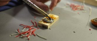
Quite often, a break in the wire leading to the plug occurs on the headset - according to experts, this is the most common defect that occurs due to frequent kinks and various mechanical damage.
Inside the cable there are several very thin and delicate wires that can easily break from strong tension or jerking. Is it possible to repair a headphone plug on your own, and what is needed for this?
Preparing for work
To repair headphones yourself, we will need:
- non-conductive glue or epoxy resin;
- a special heat-shrinkable tube is an alternative to electrical tape;
- old fountain pen;
- tester (multimeter);
- soldering iron with a thin tip and all accompanying components (tin, rosin);
- side cutters;
- mounting knife;
- lighter.
It's better to use fabric glue if you can't find epoxy resin, which only needs a few drops.
Second soldering method
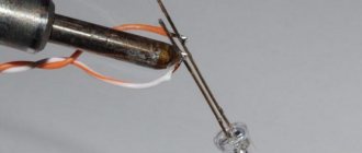
The second method, which tells you how to solder headphones by tinning the wires with sandpaper:
- The sandpaper grains should not be particularly coarse. You will need a small piece of the material itself.
- Apply a little rosin to the material, then place the wiring on it.
- Warm it up properly with a soldering iron and pull it out. The varnish on the wire will begin to soften.
- Repeat the pulling procedure until the insulation is completely scraped off.
- After repairs, insulate the area with heat shrink or electrical tape.
Some people remove the insulation using a lighter, then remove carbon deposits with alcohol and flux.
Repair algorithm
You can repair a lot of things yourself - the main thing here is the desire and ability to work with various tools. Let's look at the whole process step by step.
- Using side cutters, we bite off the plug, stepping back from it by 2-3 cm.
- We take out the headphone plug and a piece of old wire from the sealed connector - to do this, we simply cut the shell along the seam with a sharp mounting knife.
Now we can see where the wires are soldered to the plug - we take a photo for memory, so as not to confuse anything later. However, there is a standard wiring of wires coming from the headphones: copper (yellow) color - common, green - left earphone, red - right.
We remove the cut wire leading to the headphones from the varnish coating, clean and tin the ends of the wire, and connect the grounding of each channel together.
We check the plug for a short circuit, having first removed any remaining tin. The channel layout is shown in the photo:
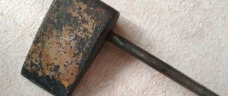
- We take the old handle, disassemble it and use only the tip - we will use it to make a new housing for the plug we disassembled.
- Using side cutters of the required length, we cut off a heat-shrinkable tube, which, instead of electrical tape, will protect the wires from sharp bending at the very exit of the new plug.
- We put the future housing on the wire, then the tube, and proceed to the final installation. How to solder wires so as not to mess anything up? There is a photograph taken earlier for this.
- Before packing everything into a tube with heat shrink, we do a check - put on headphones, use the multimeter probes to touch the contacts of different channels one by one, and you should hear rustling or clicking noises. You can try plugging the unfinished structure into the phone jack and turning on the radio. If you connect to an MP3 player to listen to music, you can use the balance to check how each channel works.
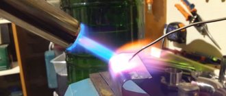
- If the test result is positive, we put a tube over the soldering area and, using an open flame of a lighter, “squeeze” it so that it firmly covers the open part of the plug, as shown in the photo.
- We dilute a few drops of epoxy, apply it to the tube, put on the body, and set everything aside for several hours for the components to completely polymerize.
That's the whole process of how to fix headphones from a mobile phone or laptop headset.
Thermal tube instead of tape
Using tape is not entirely kosher. Therefore, I propose to improve the technology a little, again without a soldering iron.
You will have to buy a heat-shrinkable tube, also known as thermal casing, at an electronics store or hardware store. This is such a clever tube that can shrink in diameter by at least half when heated. This miracle costs about $0.1 - $0.5 per meter.
We will need two thermal tubes with different diameters: 1-2 mm for the first and 4-5 mm for the second.
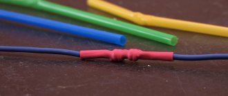
We put pieces of thin thermal tube on our twists. We cut the pieces with one and a half margin.
Now you need to heat the thermo tube. Usually I did this with a soldering iron, but we agreed that I didn’t have one, and the story was about how to fix headphones without a soldering iron, so I had to get out.
The method turned out to be quite effective and the thermo-tubes shrank. You can also use any other heater or put them in boiling water like Easter eggs. In principle, people can do it with a regular hairdryer.
While the thermotube is still hot, you can further flatten it with your fingers, then it will slightly stick together inside.
This thermo-tube must subsequently be put on the joint and also compressed with the heat of the lamp. In general, you can squeeze lighters on fire, but you can accidentally set fire to excess.
I used a piece 8-10 cm long. To strengthen the structure, the end of the thermal tube was put directly on the elastic band of the connector.
Wiring diagrams for wires with more than two cores
Users often wonder whether it is possible to repair headphones of a more complex design when there are more wires inside? A different number of wires may be suitable for one plug - this depends on the class of headphones:
Now we will tell you in more detail about each class, except the first.
Three cores
Each earphone must have two wires in the same braid or in different ones - this is a plus and a minus. Sometimes at the end, when connecting to a plug, designers combine the negative ones into one harness and get 3 pieces at the output. To make it clear to all users, we provide a detailed wiring diagram for the plug, where you can see exactly where the wires need to be soldered according to their color design.
There is no strict standard for coating with colored varnish. For example, the left channel wires can be blue, white or green.
Four wires
There are two different options here.
- Ordinary headphones without a microphone and control buttons. 4 wires are connected to the plug: a minus from each copper-colored speaker and a plus (blue with red or green with red). For convenience, the negatives are twisted into one bundle and the result is three wires that need to be soldered to their specific places.
- Headset with microphone. Here the plug has 4 types of contacts: one from each speaker, one for the microphone, and there is room left for soldering a common wire or ground. Schematically, such soldering looks like this:
Important! At first glance, the microphone wire looks like one wire, but in fact there are two of them: a very thin wire in a PVC sheath is wrapped on top with a copper wire with colorless enamel for protection.
5 cores or more
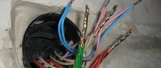
Different types of headsets of the latest class may have from 5 to 10 separate veins, so it will be much more difficult to navigate. The signal wire from the microphone is always braided in one color, and the rest come in all sorts of shades. No specialist can tell you exactly which wire should be soldered where. How to replace the wire from the plug on the headphones in this case? The only method that works here is this: we check each vein with a multimeter to determine whether it goes to the left or right speaker, then we find the common ones and combine them into one flagellum.
Read also: Switch designation on the GOST diagram
You need to solder it to the plug according to the diagrams that we showed, or find a separate diagram on the Internet that is suitable for your case.
Repair your headset or headphones for your mobile phone using this method and save money from your home budget.
So, let's go fix the headset jack
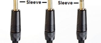
First, let's look at the headset jack itself. It's called 4-pin Jack 3.5mm , but somehow it doesn't make any difference. So, it has 4 contacts, and each contact has its own purpose. There are two standards for pin layout:
In this piece of art I tried to depict the purpose of the pins. M- and M+ are microphone contacts. The other three are the headphone contacts already familiar to you from the first article : G - ground, R - right, L - left. The colors with which the contacts are painted are not random; these are standard colors that are most often used by manufacturers to distinguish wires.
Now the first option has almost completely died out. And this is not due to the fact that the second traffic lights on the contacts are more correct and not even with the Rastafarian tricolor, but with problems of compatibility with 3-pin connectors of laptops, players... I think everyone has come across headphones that play normally from a laptop only when they are not inserted all the way. This is the first option.
But let's return to the colors of the headset wiring. In order not to be unfounded, here is a cut cable from a Beats Tour headset. Classic wire color scheme:
But alas, everything is not always so good and the manufacturer does not always make our life so easy. It is not possible to consider absolutely all color scheme options. And it doesn’t make sense, it’s better to understand how to determine which wiring is responsible for what in any circuit. This is what we will do