It often happens that a problem cannot be solved because the necessary formula is not at hand. Deriving a formula from the very beginning is not the fastest thing, but every minute counts for us.
Below we have collected together the basic formulas on the topic “Electricity and Magnetism”. Now, when solving problems, you can use this material as a reference so as not to waste time searching for the necessary information.
Daily newsletter with useful information for students of all directions - on our telegram channel.
Magnetism: Definition
Magnetism is the interaction of moving electric charges through a magnetic field.
A field is a special form of matter. Within the standard model, there are electric, magnetic, electromagnetic fields, a nuclear force field, a gravitational field and the Higgs field. Perhaps there are other hypothetical fields that we can only guess about or not guess at all. Today we are interested in the magnetic field.
Earth's magnetosphere
The magnetosphere is the space adjacent to a celestial body and has special properties that are determined by the interaction of the planet’s magnetic field with charged particles from external space. For the Earth, the diameter of this sphere is more than 90 thousand kilometers.
Our planet has main and alternating magnetic fields. The first is formed by electric currents generated on the dense core due to temperature differences. The second is formed due to the action of external forces (electric currents in the atmosphere) and is characterized by great instability. Phenomena such as magnetic storms and northern lights are associated with it.
The Earth's field space can be described by a number of indicators, for example, its intensity describes strength and is tied to geographic latitude. Magnetic declination shows the difference between the meridian (with the vector pointing north) and the corresponding position of the magnetic needle.
Magnetic induction
Just as charged bodies create an electric field around themselves, moving charged bodies generate a magnetic field. The magnetic field is not only created by moving charges (electric current), but also acts on them. In fact, a magnetic field can only be detected by its effect on moving charges. And it acts on them with a force called the Ampere force, which will be discussed later.
Magnetic field image using field lines
Before we start giving specific formulas, we need to talk about magnetic induction.
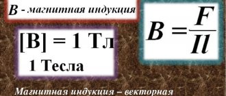
Magnetic induction is a force vector characteristic of a magnetic field.
It is designated by the letter B and is measured in Tesla ( T ). By analogy with the strength for the electric field E, magnetic induction shows the force with which the magnetic field acts on the charge.
By the way, you will find many interesting facts on this topic in our article about the theory of magnetic field and interesting facts about the Earth’s magnetic field.
How to determine the direction of the magnetic induction vector? Here we are interested in the practical side of the issue. The most common case in problems is a magnetic field created by a conductor with current, which can be either direct, or in the shape of a circle or a coil.
To determine the direction of the magnetic induction vector, there is a right-hand rule . Get ready to engage abstract and spatial thinking!
If you take the conductor in your right hand so that the thumb points in the direction of the current, then the fingers curled around the conductor will show the direction of the magnetic field lines around the conductor. The magnetic induction vector at each point will be directed tangentially to the lines of force.
Mechanical rotation
Important abbreviations: PB - gimlet rule, RS - angular velocity, RPR - right hand rule. The formulation of the PB for mechanical rotation is defined as follows: If you start screwing the drill in the direction in which the body is spinning, it will be twisted in the direction where the steering wheel tends. As expected, everything here is simple and clear. But PPR in mechanics is defined noticeably differently. This rule in this case looks and works like this:
- If you take an object in your right hand;
- Then you will begin to twist it in the direction in which all your fingers are pointing to you, except the thumb;
- Then the last remaining finger will indicate to us where the control system will tend during such rotation.
Absolutely, you can also find the side in which the angular momentum will be directed.
This was expected, because angular momentum is directly proportional to angular velocity with a positive (!) coefficient. It will look similar for the angular momentum. But let's return to our wonderful screw rule and see how this approach works for the moment of force.
Ampere power
's imagine that there is a magnetic field with induction B. l in it , through which a current of force I , then the field will act on the conductor with a force:
This is the Ampere force . Angle alpha is the angle between the direction of the magnetic induction vector and the direction of the current in the conductor.
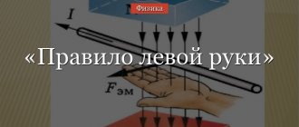
The direction of the Ampere force is determined by the left hand rule: if you position your left hand so that the lines of magnetic induction enter the palm, and the outstretched fingers indicate the direction of the current, the extended thumb will indicate the direction of the Ampere force.
MI vector direction
The direction of magnetic fields can be indicated by a magnet arrow placed in these fields. It will spin until it stops. The northern end of the arrow will show where B→ the unit vector of a particular field is oriented.
Magnetic induction lines
The frame with current behaves in the same way, having the ability to navigate the MP without interference. The direction of the induction vector indicates the orientation of the normal to such a closed electromagnetic circuit.
Attention! The rule of the gimlet (right screw) is used here. If the screw is rotated in the direction of the current in the frame, then the forward movement of the screw will coincide with the direction of the positive normal.
In some cases, the right-hand rule is used to find direction.
Visual display of MI lines
The line to which a tangent can be drawn, coinciding with B→, is called the magnetic induction (MI) line. Using such lines, you can visually display the magnetic field. These are closed contour lines that cover currents. Their density is always proportional to the value of B→ at a specific point in the MP.
Information. When dealing with the magnetic field of direct motion of charged particles, these lines are depicted as concentric circles. They have their center located in a straight line with the current, and are located in planes located at right angles to it.
The direction of magnetic lines can also be determined using the gimlet rule.
Lorentz force
We found out that the field acts on a current-carrying conductor. But if this is so, then initially it acts separately on each moving charge. The force with which a magnetic field acts on an electric charge moving in it is called the Lorentz force . What is important here is that the magnetic field does not act on stationary charges.
So, a particle with charge q moves in a magnetic field with induction B at speed v , and alpha is the angle between the particle velocity vector and the magnetic induction vector. Then the force that acts on the particle is:
How to determine the direction of the Lorentz force? According to the left hand rule. If the induction vector enters the palm and the fingers point in the direction of the velocity, then the bent thumb will show the direction of the Lorentz force. Note that this is how the direction is determined for positively charged particles. For negative charges, the resulting direction must be reversed.
If a particle of mass m flies into the field perpendicular to the induction lines, then it will move in a circle, and the Lorentz force will play the role of a centripetal force. The radius of the circle and the period of revolution of a particle in a uniform magnetic field can be found using the formulas:
Gimlet rule for moment
A moment of force is a vector of force that causes the rotational motion of an object. Torque is related to other quantities, such as the work done when a body rotates. Although the algorithm works in a similar way, let us formulate the screw (gimlet) rule for the moment of force. If you rotate the corkscrew to where the forces are displacing the body, then the direction in which the tool is screwed will indicate the direction of the torque. For the right hand, the rule sounds like this: mentally taking an object in the right hand, the object is moved in the direction of the four fingers (their orientation should coincide with the side where the forces are trying to move the object), while the straightened thumb will indicate the vector of the torque.
Interaction of currents
Let's consider two cases. The first is that current flows through a straight wire. The second is in a circular turn. As we know, current creates a magnetic field.
In the first case, the magnetic induction of a wire with current I at a distance R from it is calculated by the formula:
Mu is the magnetic permeability of a substance, mu with index zero is the magnetic constant.
In the second case, the magnetic induction in the center of a circular coil with current is equal to:
Also, when solving problems, the formula for the magnetic field inside the solenoid can be useful. A solenoid is a coil, that is, many circular turns with current.
Let their number be N , and the length of the solenoid itself be l . Then the field inside the solenoid is calculated by the formula:
By the way! For our readers there is now a 10% discount on any type of work
Changes in the Earth's magnetosphere
The characteristics of the earth's MF change mainly due to the fact that it shifts relative to the globe. People are accustomed to the idea that the northern end of the arrow should point north. With reverse magnetization of the planet's dipole, the situation will be the opposite. Observatories record data on the state of the planet’s magnetic field, and geomagnetic maps are created on their basis. They demonstrate the presence of deviations in the magnetic field strength and the position of field lines in some corners of the Earth. These phenomena are called magnetic anomalies. They are sometimes used as indicators of the location of certain fossil resources.
The relationship between induction and field strength is widely used in calculations. It allows you to derive expressions for finding the value of induction in conductors of different shapes, made of materials with different magnetic permeability.
Magnetic flux and emf
If magnetic induction is a vector characteristic of a magnetic field, then magnetic flux is a scalar quantity, which is also one of the most important characteristics of the field. Let's imagine that we have some kind of frame or contour that has a certain area. Magnetic flux shows how many lines of force pass through a unit area, that is, it characterizes the intensity of the field. It is measured in Webers (Wb) and denoted F.
S – contour area, alpha ( perpendicular) to the contour plane and vector B.
When the magnetic flux through a loop changes, an emf equal to the rate of change of the magnetic flux through the loop. By the way, you can read more about what electromotive force is in another of our articles.
Essentially, the formula above is the formula for Faraday's law of electromagnetic induction. We remind you that the rate of change of any quantity is nothing more than its derivative with respect to time.
The opposite is also true for magnetic flux and induced emf. A change in current in the circuit leads to a change in the magnetic field and, accordingly, a change in the magnetic flux. In this case, a self-induction EMF arises, which prevents a change in the current in the circuit. The magnetic flux that penetrates the current-carrying circuit is called its own magnetic flux, is proportional to the current strength in the circuit and is calculated by the formula:
L is a proportionality coefficient called inductance, which is measured in Henry (H) . The inductance is affected by the shape of the circuit and the properties of the medium. For a coil with length l and number of turns N, the inductance is calculated by the formula:
Formula for self-induced emf:
Electromagnetic phenomena (page 5)
If you increase the strength of the test current or the length of the element by a certain number of times, then the force acting on the test current element will change by the same number of times.
The ratio of the force acting on the test current element to the product of the current strength and the length of the element will remain a constant value, independent of the force, the magnitude of the current, and the length of the element. This relationship is denoted by the letter B
and is taken as the strength characteristic of the magnetic field.
The corresponding physical quantity is called MAGNETIC FIELD INDUCTION
.
MAGNETIC FIELD INDUCTION is a vector physical quantity equal to the ratio of the force acting on an element of the length of a conductor placed at a given point in the field to the product of the current strength and the length of the element.
MAGNETIC INDUCTION VECTOR MODULE IS EQUAL TO:
The magnetic field induction shows what the force acting on a conductor element with a current of unit length is equal to, if a current of unit strength flows through it.
To get a unit of magnetic field induction, you need to substitute the units of force - 1N, current - 1A, length - 1m - into the defining equation of induction. We get: .
This unit has its own name 1T (
1 Tesla).
For clarity, magnetic fields in the drawings are depicted using field lines.
MAGNETIC FIELD LINES are lines whose tangents to each point coincide with the magnetic field induction vector.
The direction of the magnetic field lines is determined by the GIMLE RULE
(or
RIGHT SCREW
):
IF THE GILMET IS ROTATED SO THAT IT MOVES ALONG THE CURRENT, THEN THE DIRECTION OF ROTATION OF THE GILMET HANDLE COINCIDES WITH THE DIRECTION OF THE MAGNETIC FIELD LINES
.
Based on the density of the field lines, the induction of different magnetic fields can be compared.
The magnitude of the magnetic field induction of a direct INFINITELY LONG current at a given field point is directly proportional to the strength of the current creating this field, and inversely proportional to the distance from this current to a given field point:
To find the value of the force (called AMPERE FORCE
), acting on a conductor placed in a magnetic field, you need to know the magnitude of the magnetic field induction, the strength of the current flowing through the conductor, the length of the conductor and the angle between the direction of the current and the vector of the magnetic field induction.
The direction of the Ampere force is determined by the LEFT HAND RULE: IF THE PALM OF THE LEFT HAND IS POSITIONED SO THAT IT INCLUDES MAGNETIC FIELD INDUCTION LINES, THE FOUR FINGERS ARE DIRECTED WITH THE CURRENT (OR AGAINST THE MOVEMENT OF NEGATIVE CHARGES), THEN THE BENDED 90 DEGREES MORE THE FINGER WILL SHOW THE DIRECTION OF THE FORCE ACTING TO CONDUCTOR
If the Ampere force is a force acting from a magnetic field on all charged particles performing directed motion inside a conductor, then the Lorentz force is a force acting from a magnetic field on a single moving charged particle.
, where N is the number of charged particles moving inside the conductor.
Current strength I
can be represented in terms of the charge q of all particles and the time
t
during which this charge flows through the cross section of the conductor: .
The charge of all particles, in turn, is equal to the product of the charge of one particle q0
by the number of
particles
N
:
q = q 0 N. Thus:
The direction of the Lorentz force, like the Ampere force, is determined by the left-hand rule.
If a magnetic field at a point is created by several currents, then the resulting induction is found as the vector sum of the field inductions created by each current independently of other currents. This rule is called the PRINCIPLE OF SUPERPOSITION OF MAGNETIC FIELDS.
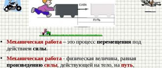
If, under the action of the Ampere force, a conductor moves in a magnetic field, then the magnetic field does work. The magnitude of this work depends on the strength of the current flowing through the conductor and on the magnetic flux penetrating the area swept by the moving conductor.
MAGNETIC FLUX is defined as a physical quantity equal to the product of the perpendicular component of the magnetic field induction and the area that it penetrates:
To get a unit of magnetic flux, you need to substitute the units of induction - 1 T and area - 1 m2 into its defining equation. We get:
This unit has its own name 1 Wb (1weber).
§3. Substances in a magnetic field
It is known that magnetic fields can be obtained using conductors through which current flows and permanent magnets. The materials used to make permanent magnets are special grades of steel and some alloys. These same and some other substances can significantly increase the induction of the magnetic field of the current.
The question arises: HOW DO SUBSTANCES WITH STRONG MAGNETIC PROPERTIES DIFFER FROM OTHER SUBSTANCES?
This question can only be answered by understanding the nature of magnetism in general.
To do this, we can start from Ampere’s hypothesis about the existence of molecular, or more precisely intra-atomic, currents in any body.
According to this hypothesis, magnetic properties should be inherent in all bodies without exception.
One of the plausible versions that allows one to imagine the mechanism of magnetization of substances is the assumption that the magnetic field of an atom appears due to the orbital motion of electrons.
If this is so, then there should probably be two classes of substances with uncompensated and compensated magnetic fields in their individual atoms.
When substances belonging to the first group enter a magnetic field, the latter will arrange atoms in such a way that the induction vectors of the external field and each atom will be co-directed. Due to this, the external magnetic field should decrease.
The magnetic permeability of such substances is greater than unity and they will be weakly drawn into the magnetic field.
Experience shows that such substances really exist. They are called PARAMAGNETS.
For substances of another class, the number of electrons in atoms must be even. Moreover, if there are two electrons in the same orbit, they should rotate in different directions.
In this case, it is clear that the induction vectors of the magnetic field created by each such electron will be equal in magnitude and opposite in direction. Regardless of the orientation of the atoms, substances of this type should not have magnetic properties.
If such substances get into a magnetic field, the situation changes.
The rotating electrons will be acted upon by the Lorentz force, and since the electrons move in different directions, the force acting on them will also be directed in different directions.
Due to this, the numerical values of the electron velocities should change. For one electron the speed will increase, for the other it will decrease.
The induction of magnetic fields created by electrons will change accordingly. The atom will have its own magnetic field and it will be directed against the field that caused the described effect.
The magnetic permeability of such substances is less than unity and they will be weakly pushed out of the magnetic field.
Experience shows that such substances exist. They are called DIAMAGNETICS
.
The developed model allows us to understand the nature of magnetism and is a necessary step to answer the question posed at the beginning.
In addition to the situations described, one can imagine another case when a substance has local regions of magnetization, where the magnetic fields of a huge number of atoms are already directed in one direction.
The total magnetic field of many local regions can be zero if these regions in the body are oriented differently.
With an increase in the external magnetic field, due to the rearrangement of atoms, the areas of magnetizations that do not coincide with this field will decrease, and those that coincide will increase.
The magnetic permeability of such materials must be very high.
Such substances are called ferromagnets
.
Ferromagnets find very wide application in technology. They are used to make permanent magnets and electromagnets, transformer cores and current generators; they cover films for tape recorders and computer disks.
According to the described mechanism, objects made of ferromagnets can be magnetized by placing them in an external magnetic field.
Indeed, even in the relatively weak magnetic field of the Earth, it is possible to magnetize a steel rod by orienting it in the direction of the magnetic induction lines and hitting the end with a hammer.
If ferromagnets can be magnetized, then it is probably possible to carry out the reverse process of their demagnetization, for example, by increasing the intensity of the thermal motion of particles.
An experiment with heating a magnetized steel needle confirms this assumption.
Similar experiments with other ferromagnets show that they all have a certain temperature, different for different substances, and called the CURIE POINT
, ferromagnetic properties disappear.
§4. Some applications of magnetic phenomena
We encounter magnetic phenomena in life; they are widely used in technology.
Since the Earth has a magnetic field, a magnetic needle can make it possible to navigate on its surface.
A strong magnetic field can be obtained using a current-carrying coil into which a steel core is inserted. Such a device is called an ELECTROMAGNET
.
Magnetized films coated with a special composition can store various information for a very long time.
But magnetic phenomena are not always used to benefit humans.
Thus, in military affairs, mines are used that react to magnetic fields created by the magnetized steel hulls of ships.
To avoid being blown up by such mines, ships must be demagnetized. This operation can be carried out using conductors through which an electric current of a certain strength and direction is passed, depending on the nature of the ship's magnetization.
EXAMPLE OF SOLVING A PROBLEM
In a horizontal plane on parallel conductive rails, the distance between which is L
, the conductor lies.
The entire system is placed in a magnetic field with induction B
.
How much current must be passed through the conductor so that it moves along the rails at a constant speed?
Coefficient of sliding friction of a conductor on rails - m
. The angles between the magnetic field induction vector, the direction of the current in the conductor and the speed of its movement are straight.
This problem can be classified as static, for the reason that the conductor, according to the conditions of the problem, must move at a constant speed.
A body moves at a constant speed if the sum of the forces acting on it is zero.
I flows through a conductor located in a magnetic field
, the Ampere force acts on the conductor.
The direction of this force can be determined by the left-hand rule. To do this, you need to position your left hand so that the lines of force enter the palm.
Four fingers should be directed along the current, then the thumb bent by 900 will show the direction of the Ampere force.
If the conductor moves at a constant speed, then there must be a force directed in the opposite direction and equal in magnitude to the Ampere force.
| B + + + I + + + FA Ftr + + + + + + + + + + |
Since there is friction between the conductor and the rails, it is likely that this force could be the sliding friction force.
The sum of the forces acting on the conductor is zero, which means the Ampere force is equal to the friction force:
Once we have written down this equality, it is enough to remember that the Ampere force is equal to the product of the current flowing through the conductor, the length of the active part of the conductor located in the magnetic field, and the magnetic field induction:
Since the angle between the magnetic induction vector and the direction of the current is 900, then sin900 = 1.
The friction force is equal to the product of the friction coefficient and the normal pressure force:
If the rails are horizontal, then the normal pressure force is equal to the force of gravity:
We substitute the expression for the Ampere force and the friction force into the original equation and obtain an expression from which we can find the value of the current we are interested in: .
TASKS FOR INDEPENDENT SOLUTION
Task No. 1
Having passed a potential difference of 2000 V, the electron flies into a uniform magnetic field with an induction of 150 mT and moves in it along a circular arc with a radius of 1 m (in a plane perpendicular to the magnetic field).
What is the ratio of the charge of an electron to its mass (specific charge of an electron).
Task No. 2
L hangs on two thin threads
and mass
m
.
The rod is in a uniform magnetic field, the induction vector of which is directed vertically downward. At what angle will the thread deflect if a current of force I
?
Task No. 3
In a horizontally located conductor 20 cm long and weighing 4 g, the current strength is 10 A. Find the induction (module and direction) of the magnetic field in which the conductor must be placed so that the force of gravity is balanced by the Ampere force.
Task No. 4
An electron moves in a uniform magnetic field with induction B =
4 mT. Find the electron's orbital period.
Problem #5
In a conductor with an active part length of 8 cm, the current strength is 50 A. It is in a uniform magnetic field. Under the action of the Ampere force, the conductor moved 10 cm perpendicular to the lines of force, and at the same time 8 mJ of work was done. Find the magnetic field induction.
Chapter 5
ELECTROMAGNETIC INDUCTION
In 1820, a Danish physicist experimentally established the connection between electric current and magnetic field. The essence of Oersted's experiments was that if an electric current passed through a conductor, a magnetic field arose around the conductor, which could be examined using a magnetic needle.
In the not very precise language of the science of the time, when similar experiments were first carried out, “Electricity gave rise to magnetism.”
Oersted's discovery, made as a result of a simple experiment, served as an impetus for the development of a new direction in natural science - the doctrine of electromagnetism. In addition to the fact that this discovery entailed a chain of new fundamental experiments in the field of studying the connections between electrical and magnetic phenomena (the study of the interaction of parallel currents by A. Ampere), it led to a number of important inventions, in particular, the electromagnet (1820, F. Arago), electric motor, M. Faraday) and gave an objective method for measuring electricity, it prompted a number of naturalists to think :
if electricity generates magnetism, then could magnetism generate electricity?
This is exactly how they set themselves the task: to find the connection between magnetism and electricity A. Ampere and M. Faraday. But Ampère soon abandoned the solution to the problem and even tried to convince Faraday to follow his example. However, Faraday's tenacity evokes surprise and admiration. Convinced of the existence of not only a direct connection between electricity and magnetism, but an inverse connection, he searched for this connection for 11 years. Of course, during this time Faraday did not limit himself only to solving this problem; he did many other things and solved other problems. The search was also made difficult by the lack of materials necessary for the experiments. Faraday did not even have the usual insulated wire at his disposal. He also did not have sensitive instruments capable of registering the weak effects he was looking for. In a number of cases, Faraday came extremely close to the discovery, then moved away from it again.
The situation was similar for other researchers. The history of science knows a truly sad fact for one of its representatives. In 1825, Colladon conducted an experiment that gave the same result that Faraday later obtained. However, in order to eliminate the influence of a powerful magnet on the electrical measuring device, the latter was moved to another room. By the time Colladon reached the device, all movement of its needle had stopped. The effect was not registered!
The American physicist D. Henry sought and found the answer to the question about the possibility of magnetism generating electricity independently of Faraday. But Henry was late in publishing his results, and the priority of the discovery of the phenomenon, called the phenomenon of electromagnetic induction, belongs to the English physicist M. Faraday.
Faraday carried out his experiments on homemade instruments, very primitive from our point of view and also insensitive.
The effects recorded by Faraday can be observed in a slightly modified form using modern instruments.
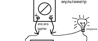
Let's assemble an installation consisting of a wire coil and a galvanometer connected to each other, a device used to detect electric current in a closed circuit, to determine its magnitude and direction.
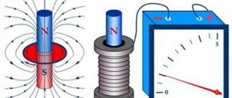
We will insert a permanent magnet into the coil with the north pole. The galvanometer needle deviates to the right.
When the magnet is at rest, the galvanometer needle points to zero.
When the magnet is removed from the coil, the galvanometer needle deviates to the left.
We insert the magnet into the coil with the south pole, and
the galvanometer needle deviates to the left.
When the magnet is at rest, the needle points to zero.
When the magnet is removed from the coil, the galvanometer needle deviates to the right.
Let's change the speed of the magnet relative to the coil.
When the magnet moves slowly relative to the coil, the current in the circuit is less than when the magnet moves quickly.
Let's assemble an installation consisting of two circuits not connected to each other. The first circuit consists of a DC source, a rheostat, a switch and a wire coil connected in series. The second circuit is an indicator circuit. It consists of a galvanometer and another wire coil. One coil is inside the other. The coils are motionless relative to each other.
Using a rheostat we will change the current strength in the first circuit.
The galvanometer needle deviates from the zero division, which indicates the presence of current in the indicator circuit.
When the current in the first circuit increases, the galvanometer needle deflects in one direction, and when it decreases, in the other.
When the current in the first circuit does not change, the galvanometer needle points to zero.
Let's insert a steel core inside the second coil.
When the steel core moves, the arrow of the device will deviate either to the right or to the left, depending on the direction of its movement.
If the core is at rest relative to the coil, the instrument needle does not deviate.
We will move the coil with the steel core placed inside it relative to another coil.
The arrow of the device deviates either to the right or to the left, depending on the direction of movement of the coil. In this case, the amount of deflection of the device needle is significantly greater than in the case of a similar movement of a coil without a core.
We will turn the current source on and off.
When the current source is turned on, the arrow of the device deviates to the right from the zero division. When the current source is turned off, the arrow of the device deviates to the left from the zero division.
If an electric current flows through a coil, constant in magnitude and direction, the needle of an electrical measuring instrument connected to the circuit of another coil does not deviate from the zero division.
Let's connect the wire frame to a pointer electrical measuring instrument.
When the frame rotates between the poles of a permanent magnet, the electrical measuring device indicates the presence of a current in the circuit that changes in magnitude and direction.
If the frame is at rest relative to the magnet, there is no current in the circuit.
All experiments are united by the fact that in an electrical circuit that does not contain a current source, forming a closed circuit penetrated by a magnetic field, an electric current is induced (induced).
To distinguish this electric current from the electric current created by a source included in the circuit, let's call it induced current.
In different experiments, the induced current appears due to different reasons, but everywhere these reasons are associated with the magnetic field, or more precisely with its change.
In some cases, the induction of the magnetic field penetrating the circuit changes in various ways; in others, the area of the circuit penetrated by the magnetic field or its orientation relative to the magnetic field changes.
To make it easier to combine the causes of the occurrence of induced current, you can introduce a physical quantity - magnetic flux (F).
Let us call magnetic flux a physical quantity equal to the product of the magnitude of the magnetic field induction vector by the area of the contour penetrated by this magnetic field and by the cosine of the angle between the direction of the magnetic induction vector and the normal (perpendicular) to the surface bounded by the contour
: .
In the drawing, an idea of the magnitude of the magnetic flux can be reflected using a larger or smaller number of magnetic lines of force penetrating a particular circuit.
To get a unit of magnetic flux, you need to substitute the units of magnetic induction - 1 T and area - 1 m2 into its defining equation.
We get: [F] = 1 T 1 m2.
This unit has its own name - 1 Wb (Weber
).
When determining the direction of electric currents induced in a closed loop, Faraday himself proposed two different rules for the case of “voltaic-electric” and “magnetoelectric” induction.
The fact that in both cases there is the same inductive process, which obeys the general rule, was understood by the St. Petersburg academician.
To formulate Lenz's rule ,
it is necessary to return again to experiments on obtaining induction currents. These experiments can be carried out, for example, on the following installation:
At the tip there is a rocker arm with two rings that balance each other, made of non-magnetic metal (in this case, aluminum). One ring is solid, the other is cut.
We will slide a permanent magnet in and out of the rings, changing its poles.
The movement of the magnet has no effect on the cut ring.
When the magnet and the solid ring come together, the ring is repelled from the magnet.
When a magnet is removed from a solid ring, it is attracted to the magnet.
The results of the experiments do not depend on which pole of the magnet is facing the ring.
Thus, summarizing the results of observations, we can construct the following chain of judgments.
1. Once the ring begins to interact with the magnet, it means that a magnetic field arises around it.
2. Since the ring is made of non-magnetic metal, this field can be generated by current flowing through the ring.
3. Since interaction appears only when the ring and magnet move mutually, the current in the ring appears due to this movement.
4. When the magnet moves relative to the ring, the magnetic flux penetrating the ring changes, therefore, the current arising in the ring is inductive.
5. Since when the ring and magnet approach each other, they repulse, the induction vector of the magnetic field of the magnet is directed opposite to the induction vector of the magnetic field of the ring.
6. Since when the ring and the magnet move away from each other, their attraction occurs, the induction vector of the magnetic field of the magnet is co-directed with the vector of the magnetic field of the ring.
7. In all cases, the direction of the induction current can be determined based on the rule:
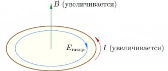
When the magnetic flux penetrating a closed circuit changes, an induced current appears in the circuit in such a direction that the magnetic field generated by it creates a magnetic flux that prevents the change in the magnetic flux generating the induced current.
Specifically, the direction of the induced current in the conductor and the sign of the resulting EMF can be determined as follows.
Let us consider the case when a magnet is introduced into a conducting ring. The magnetic flux penetrating the ring increases. The vector of the induction of the magnetic field of the magnet is co-directed with the vector of the speed of the magnet.
In this case, the induction vector of the magnetic field created by the induction current is directed against the speed of the magnet.
By rotating the right screw so that the direction of rotation of the handle coincides with the direction of the magnetic field lines created by the induction current (or, which is the same, it is opposite to the direction of movement of the magnet), we determine the direction of the induction current in the direction of movement of the screw. In our case, the current is directed counterclockwise.
| Due to the large volume, this material is placed on several pages: 5 |
Get text
Magnetic field energy
Electricity, nuclear energy, kinetic energy. Magnetic energy is a form of energy. In physical problems, most often it is necessary to calculate the energy of the magnetic field of a coil. The magnetic energy of a coil with current I and inductance L is equal to:
Volumetric field energy density:
Of course, these are not all the basic formulas of the “electricity and magnetism” section of physics, but they can often help in solving standard problems and calculations. If you come across a problem with an asterisk, and you just can’t find the key to it, make your life easier and contact the student help service for a solution.
Basic formulas of the section “Electromagnetic induction”
Algorithm for solving problems on the topic “Electromagnetic induction”:
1. Carefully read the conditions of the problem. Establish the reasons for the change in the magnetic flux penetrating the circuit.
2. Write down the formula:
- law of electromagnetic induction;
- induced emf in a moving conductor, if the problem considers a progressively moving conductor; If the problem considers an electrical circuit containing a current source and an induced emf arising in one of the sections, caused by the movement of a conductor in a magnetic field, then you first need to determine the magnitude and direction of the induced emf. After this, the problem is solved by analogy with problems for calculating a direct current circuit with several sources.
3. Write down an expression for the change in magnetic flux and substitute it into the formula for the law of electromagnetic induction.
4. Write down all additional conditions mathematically (most often these are the formulas of Ohm’s law for a complete circuit, Ampere force or Lorentz force, formulas of kinematics and dynamics).
5. Solve the resulting system of equations for the desired value.
6. Check the solution.
Electromagnetic oscillations and waves →
← Magnetic field
Electromagnetic induction
3.2 (64.8%) 50 votes