Hello dear readers of the site. Every radio amateur, in his home laboratory, must have adjustable power supply, allowing you to produce a constant voltage from 0 to 14 Volts at a load current of up to 500mA. Moreover, such a power supply must provide short circuit protection
at the exit, so as not to “burn” the structure being tested or repaired, and not to fail yourself.
This article is primarily intended for beginner radio amateurs, and the idea of writing this article was suggested by Kirill G
. For which special thanks to him.
I bring to your attention a diagram of a simple regulated power supply , which I assembled back in the 80s (at that time I was in the 8th grade), and the diagram was taken from the supplement to the magazine “Young Technician” No. 10 for 1985. The circuit differs slightly from the original by changing some germanium parts to silicon ones.
As you can see, the circuit is simple and does not contain expensive parts. Let's take a look at her work.
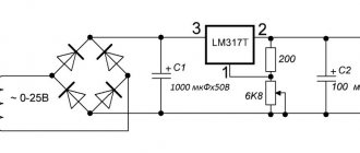
Schematic diagram of the power supply.
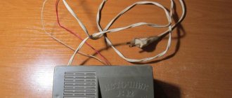
The power supply is plugged into the outlet using a two-pole plug XP1
.
When switch SA1
, 220V voltage is supplied to the primary winding (
I
) of step-down transformer
T1
.
Transformer T1
reduces the mains voltage to
14
-
17
Volts.
This voltage, removed from the secondary winding ( II
) of the transformer, is rectified by diodes
VD1
-
VD4
, connected in a bridge circuit, and smoothed by filter capacitor
C1
. If there is no capacitor, then when powering the receiver or amplifier, an AC hum will be heard in the speakers.
Diodes VD1
—
VD4
and capacitor
C1
form
a rectifier
, from the output of which a constant voltage is supplied to the input
of a voltage stabilizer
, consisting of several circuits:
1. R1
,
VD5
,
VT1
;
2. R2
,
VD6
,
R3
;
3. VT2
,
VT3
,
R4
.
Resistor R2
and the zener diode
VD6
form
a parametric stabilizer
and stabilize the voltage across the variable resistor
R3
, which is connected in parallel with the zener diode. Using this resistor, the voltage at the output of the power supply is set.
On variable resistor R3
a constant voltage is maintained equal to the stabilization voltage
Ust
of this zener diode.
When the variable resistor slider is in its lowest (according to the diagram) position, transistor VT2
is closed, since the voltage at its base (relative to the emitter) is zero, and accordingly,
the powerful
transistor
VT3
is also closed.
With transistor VT3
collector-emitter
junction reaches several tens of megaohms, and almost all of the rectifier voltage
drops
at this junction.
Therefore, there will be no voltage at the output of the power supply (terminals XT1
and
XT2
).
When is transistor VT3
is open, and the resistance of
the collector-emitter
is only a few ohms, then almost all of the rectifier voltage is supplied to the output of the power supply.
So here it is. As the variable resistor slider moves upward, to the base of transistor VT2
an unlocking
will arrive , and current will flow in its emitter circuit (EC).
At the same time, the voltage from its load resistor R4
is supplied directly to the base of the powerful transistor
VT3
, and voltage appears at the output of the power supply.
The more
negative unlocking voltage at the base of transistor
VT2
, the
more
both transistors open, the
greater
the voltage at the output of the power supply.
The highest voltage at the output of the power supply will be almost equal to the stabilization voltage Ust
Zener diode
VD6
.
Resistor R5
simulates the load of the power supply when
nothing is connected
XT1
and
XT2 To monitor the output voltage, a voltmeter is provided, consisting of a milliammeter
and an additional resistor
R6
.
On transistor VT1
, diode
VD5
and resistor
R1,
a short circuit protection unit is assembled between sockets
XT1
and
XT2
.
Resistor R1
and the direct resistance of the diode
VD5
form a voltage divider, to which transistor
VT1
.
In operating condition, transistor VT1
is closed with a positive (relative to the emitter) bias voltage at its base.
If there is a short circuit at the output of the power supply, the emitter
transistor
VT1
will be connected to the anode of diode
VD5
, and a negative bias voltage will appear at its base (relative to the emitter) (voltage drop across diode
VD5
).
Transistor VT1
will open, and
the collector-emitter
will bypass the zener diode
VD6
.
As a result of this, transistors VT2
and
VT3
will be closed.
the collector-emitter
section of the regulating transistor
VT3
will increase
sharply , the voltage at the output of the power supply
will drop
almost to zero, and such a small current will flow through the short circuit that it will not cause harm to the parts of the unit.
As soon as the short circuit is eliminated, transistor VT1
closes and the voltage at the output of the block is restored.
Circuit components
It is better to use multi-turn components of the “3296W” type as tuning resistors P3 and P4. Moreover, I did not find the values of 250 kOhm and 25 kOhm and instead put 200 kOhm and 20 kOhm.
Resistor R7 should have a power of 0.5 W. It is better to set the R4 shunt with a power of 5W (it heats up great).
For Zener diode D2 I installed a BZX55C 2V4 and for Zener diode D3 I installed 1N4740A.
The 2N3055 power transistor can be replaced with a more powerful NPN transistor, for example TIP35C, 2SC5200 or another similar one, but they cannot be installed directly into the board, the pinout is not suitable, it is necessary to edit the printed circuit board, so we install them on wires.
Transistors BC547/BC557 are replaced with BC546/BC556.
It is advisable to select the differential stage transistors (T5 and T6) according to the current transfer coefficient (h21e).
Where else might you need it?
Device power
The applications listed above for this type of device, created using high-power transistors, are only a small part of the vast scope of their application. So, a homemade power supply, assembled using powerful field-effect transistors, can be used for the following purposes:
- saving battery resources. Such batteries are expensive enough to waste on various experiments that a regulated power supply can handle;
- providing power to low-voltage power tools;
- participation in the electrification of rooms in the house, where there are high requirements for fire safety conditions. Such premises include barns, various outbuildings, as well as garages, basements, etc.;
Note! When powering devices with alternating current, due to the large amount of low-voltage wiring for electronics and household appliances, various interference can be created.
- using the device when cutting materials such as fusible plastic, foam rubber and polystyrene with heated nichrome;
- lighting design for home premises. This power supply allows you to connect LED strips to a 220 V network. This is despite the fact that the tapes themselves usually have significantly lower voltage;
Note! A well-assembled homemade power supply will provide you with stable lighting and a long service life of the LED strip itself.
LED lights
- providing power to a pond, street fountain and any other type of external illumination of the house;
- for use in bioelectric procedures;
- charge mobile portable devices (smartphones, tablets, mobile phones, etc.), as well as laptops when there is no stable source of electricity.
The above methods of using a homemade radio device of this type are not exhaustive, since the scope of application of the product is very wide and it is impossible to list everything.
Start of assembly
At the very beginning, after you decide to assemble a power supply with your own hands using powerful transistors, you should go through the existing assembly circuits.
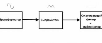
Scheme option
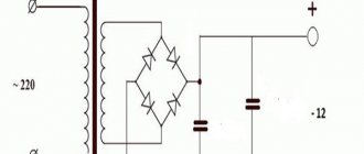
The figure shows the simplest circuit for assembling an adjustable type BN using powerful (field-effect) transistors. This scheme consists of the following elements:
- a step-down transformer;
- diode rectifier;
- capacitor smoothing filter.
These three elements are the main functional units of the device. Depending on the rated power of the homemade power supply, these units will vary in type and size.
Transformers
The most expensive and at the same time the main part of the power supply is the transformer. It is he who will lower the alternating mains voltage to the level you require. Before choosing the desired type of transistor, you should calculate the electrical power that will be needed. To get real numbers, you need to do the following calculations:
- multiply the voltage by the load current;
- We add a small reserve for power to the resulting figure. This margin should be approximately 20-30%;
- the final figure will turn out to be the required electrical power in this particular situation.
Now that everything is ready and the necessary components have been purchased, you can begin the assembly itself.
Device requirements
A homemade device must be designed for power supply under any load, including reactive load. This will significantly expand the range of applications of power supply in everyday life.
Note! The specified voltage must be maintained with high accuracy and for the required time.
At the same time, its protection circuit against powerful overloads should be available for use by other household members. You should also strictly follow the previously selected assembly diagram to avoid improper soldering of the device components together. This will avoid many problems in the future, such as breakdown of the equipment being tested, damage to the power supply itself, etc.
Required product
Any novice radio amateur dreams of assembling an adjustable power supply made using field-effect transistors. A special feature of this product is that it is possible to regulate the voltage obtained at the output. That is why this type of power supply is called “regulated”. The unit is protected against voltage surges. There is nothing complicated here, the main thing is to know the assembly diagrams and follow them exactly. A power supply of a regulated type, assembled with field-effect transistors, can be useful in the following situations:
- checking the functionality of a circuit assembled earlier for other purposes;
- when there is a need for a smooth supply of voltage;
- as a way to make your work easier in the future, since you no longer have to assemble a power supply for the required voltage level.
Homemade power supply
A power supply unit (PSU) of any type, including regulated and assembled with field-effect transistors, is an integral element, without which no circuit will work. In this case, the transistor can be quite powerful. Despite the fact that industrial products assembled using field-effect transistors are quite high-quality products, it is still more pleasant to do everything yourself. After all, here the quality will be guaranteed by your skills and knowledge in radio electronics. In addition, it is not always possible to purchase the required power supply, but you can always assemble it yourself. By deciding to make a device for your home needs yourself, you will significantly save your finances and also get a multifunctional item, which is difficult to do without in the modern world.
Transformer
The secondary winding of the transformer must be designed for a current not less than the maximum load current (1.5), and it is better that it has a reserve. The voltage of the secondary winding is selected according to the required parameters of the LBP. I recommend using a ~24V transformer for Uout=30V, since after rectification on capacitor C1 at idle the voltage will be 1.41 times higher (34V), and after the stabilizer it will drop by several volts. The use of a transformer with a ~24V winding will eliminate the need for recalculation of some circuit elements. For Uout=50V, I recommend using a transformer with a 36V secondary winding.
Also, to reduce the power dissipation on the regulating transistor, it is recommended to use a transformer with two or three secondary windings and add a toggle switch or winding switch. You can use a 12V+12V transformer and make a switch to switch voltage regulation modes from 0 to 15V and from 15V to 30V.
The LBP stabilizer can be powered from a switching power supply, then the input capacitance C1 must be reduced to several hundred microfarads.