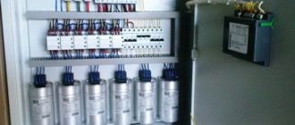
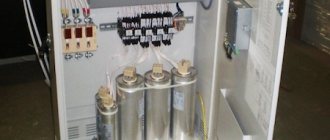
Reactive power compensation (RPC). The appearance of the term “reactive” power is associated with the need to isolate the power consumed by the load, the component that generates electromagnetic fields and provides engine torque. This component occurs when the load is inductive. For example, when connecting electric motors. Almost all household loads, not to mention industrial production, are inductive to one degree or another. In electrical circuits, when the load is active (resistive) in nature, the flowing current is in phase (neither leading nor lagging) with the voltage. If the load is inductive (motors, transformers at idle), the current lags behind the voltage. When the load is capacitive in nature (capacitors), the current leads the voltage.
The total current consumed by the motor is determined by the vector sum
1. Ia—active current 2. Iri—inductive reactive current
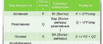
The power consumed by the engine is tied to these currents.
- P – active power is tied to Ia (for all harmonics in total)
- Q – reactive power is tied to Iri (for all harmonics in total)
- A – total power consumed by the engine. (for all harmonics in total)
Reactive power does not produce mechanical work, although it is necessary to operate the engine, so it must be obtained locally rather than being consumed by the utility. Thus, we reduce the load on wires and cables, increase the voltage at the motor terminals, reduce payments for reactive power, and have the opportunity to connect additional machines by reducing the current consumed from the power transformer.
The parameter that determines reactive power consumption is called Cos (φ)
Cos (φ) = P1harmon/ A1harmon
P1harm—active power of the first harmonic 50 Hz A1harmon—total power of the first harmonic 50 Hz where,
A = √P² + Q²
Thus, cos (φ) decreases when the reactive power consumption of the load increases. It is necessary to strive to increase cos (φ), because low cos (φ) causes the following problems:
- High power losses in electrical lines (reactive power current flow)
- High voltage drops in electrical lines (for example 330...370 V, instead of 380 V)
- The need to increase the overall power of generators, cable cross-sections, and power of power transformers.
From all of the above, it is clear that reactive power compensation is necessary. This can easily be achieved by using active compensating systems. Capacitors in which will compensate the reactive power of the motors.
Reactive power consumers
Consumers of reactive power necessary to create magnetic fields are both individual power transmission units (transformers, lines, reactors) and electrical receivers that convert electricity into another type of energy and which, according to the principle of their operation, use a magnetic field (asynchronous motors, induction furnaces, etc.) .P.). Up to 80-85% of all reactive power associated with the formation of magnetic fields is consumed by asynchronous motors and transformers. A relatively small part in the overall balance of reactive power falls on the share of its other consumers, for example, induction furnaces, welding transformers, converter units, fluorescent lighting, etc.
Transformer as a consumer of reactive power . The transformer is one of the main links in the transmission of electricity from the power plant to the consumer. Depending on the distance between the power plant and the consumer and on the electricity transmission scheme, the number of transformation stages ranges from two to six. Therefore, the installed transformer capacity is usually several times higher than the total power of the power system generators. Each transformer itself is a consumer of reactive power. Reactive power is necessary to create an alternating magnetic flux, with the help of which energy is transferred from one winding of the transformer to another.
Asynchronous motor as a consumer of reactive power . Asynchronous motors, along with active power, consume up to 60-65% of the total reactive power of the power system loads. According to the principle of operation, an asynchronous motor is similar to a transformer. As in a transformer, the energy of the primary winding of the motor, the stator, is transferred to the secondary winding, the rotor, via a magnetic field.
Induction furnaces as consumers of reactive power . Large electrical receivers that require high reactive power for their operation primarily include industrial frequency induction furnaces for melting metals. Essentially, these furnaces are powerful, but not perfect from the point of view of transformer construction, transformers, the secondary winding of which is a metal (charge) melted by currents induced in it.
Converter installations that convert alternating current into direct current using rectifiers are also large consumers of reactive power. Rectifiers are widely used in industry and transport. Thus, higher-power installations with mercury converters are used to power electrical insulating baths, for example, in the production of aluminum, caustic soda, etc. Railway transport in our country is almost completely electrified, and a significant part of the railways uses direct current converter installations.
About the nature of reactive energy
If you turn on an inductor instead of a capacitor, the essence of the process will not change.
This is the main focus of reactive energy - at the moment of the 'tide' we fill our tanks
, at the moment of low tide, we
drain their contents back
.
(or current in electrical circuits)
back and forth .
If we are tempted to drain at least a little liquid “to the left” (connect an active resistor in series with the reactive capacitor)
, then we will begin to take
“a little more”
than to return, and this
“a little more”
is already active energy by definition
(after all, we do not we return it back, right?)
, for which, as you know, you have to pay.
Or another example: suppose that we borrow a certain amount of money from a lender and immediately return to him the loan we just took. If we give back exactly as much as we took (pure reactivity), we will return to the original state and no one will owe anything to anyone. If we spend part of the loan on any purchase and return what is left of the loan after making the purchase (we add an active load to the circuit and part of the energy will leave the system)
— we will still owe. This spent portion is the active component of the loan we took.
Now you may have one very reasonable question - if everything is so simple, and in order for energy to be considered reactive, it simply needs to be completely returned back to the source, why do enterprises have to pay for the consumed (and fully returned)
reactive energy?
The thing is that in the case of a purely reactive load, the moment of the maximum consumed current (reactive)
occurs at the moment of the minimum voltage value, and vice versa, at the moment of maximum voltage at the load terminals, the current flowing through it is zero.
The flowing reactive current heats the supply conductors - but these are active losses caused by the flow of reactive current through conductors with limited conductivity, which is equivalent to an active resistor connected in series with a reactive load. Also, since at the moment of maximum reactive current the voltage at the poles of the reactive element passes through zero, the active power supplied to it at this moment (the product of current and voltage)
equal to zero. Conclusion - reactive current causes heating of the wires without doing any useful work. It should be noted that these losses are also active and will be counted by a household active energy meter.
Large enterprises are capable of generating quite large reactive currents, which negatively affect the functioning of the power system. For this reason, both the active and reactive components of consumed energy are taken into account for them. To reduce the generation of reactive currents (causing very real active losses)
, enterprises install reactive power compensation installations.
Design and principle of operation of the IRM
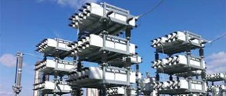
A reactive power source is a complex of electrical equipment that provides automatic control of optimal voltage levels in the distribution network. The main elements of the complex are elements such as a magnetization-controlled shunt reactor 6-500 kV (CSR), a PKU and a bank of static capacitors (BSC).
IRM significantly improves the quality of power supply and increases its reliability: it eliminates voltage fluctuations and reduces the loss of electricity during transportation and distribution. Additionally, the complex is capable of increasing the capacity of power lines, as well as avoiding technological failures as a result of disruption of the stability of the power system when a sharp decrease in voltage occurs.
Reactive power sources based on bias-controlled shunt reactors 6–500 kV, filter compensating devices and static capacitor banks (SCB):
| Name | Unom, kV** | Qр, Mvar** | QFKU, Mvar | QBSK, Mvar*** |
| IRM–6/3.6 (6.3)/3.6 | 6 | 3,6 | — | 3,6 (6,3) |
| IRM–6/6.3 (12.6)/6.3 | 6 | 6,3 | — | 6,3 (12,6) |
| IRM–6/10 (20)/10 | 6 | 10 | — | 10 (20) |
| IRM–10/3.6 (6.3)/3.6 | 10 | 3,6 | — | 3,6 (6,3) |
| IRM–10/6.3 (12.6)/6.3 | 10 | 6,3 | — | 6,3 (12,6) |
| IRM–10/10 (20)/10 | 10 | 10 | — | 10 (20) |
| IRM–35/10 (20)/10 | 35 | 10 | — | 10 (20) |
| IRM–35/16 (32)/16 | 35 | 16 | — | 16 (32) |
| IRM–35/25 (50)/25 | 35 | 25 | — | 25 (50) |
| IRM–110/25 (50)/25 | 110 | 50 | 2,5 | 25 (50) |
| IRM–110/50 (100)/50 | 110 | 50 | 5 | 50 (100) |
| IRM–220/30/100 | 220 | 100 | 10 | 30**** |
| IRM–220/50 (100)/100 | 220 | 100 | 10 | 50 (100) |
| IRM–220/100 (200)/100 | 220 | 100 | 10 | 100 (200) |
| IRM–330/10/100 | 330 | 100 | 10 | — |
| IRM–330/50/100 | 330 | 100 | 10 | up to 50**** |
| IRM–330 (500)/18/180 | 330; 500 | 180 | 18 | — |
| IRM–330 (500)/90/180 | 330; 500 | 180 | 18 | up to 90**** |
* It is possible to use other IRM schemes.
** It is possible to manufacture IRM of any rated power for any rated voltage (with 1 or 2 BSK sections).
*** The rated voltage of the BSK for IRM 6–220 kV corresponds to the rated voltage of the IRM (the capacitive power of the IRM with two sections of the BSK is indicated in parentheses).
**** The connection of the BSK for the specified IRM is carried out to the compensation winding of the reactor with a rated voltage of 10–35 kV, depending on the voltage class and power of the IRM reactor.
Power triangle and cos φ
For clarity, let us depict the total power and its components in the form of vectors (see Fig. 2). Let us denote the total power vector by the symbol S, and assign the symbols P and Q to the vectors of the active and reactive components, respectively. Since the vector S is the sum of the current components, then, according to the rule of vector addition, a power triangle is formed.
Rice. 2. power factor
Applying the Pythagorean theorem, we calculate the modulus of the vector S:
From here you can find the reactive component:
Reactive component
We have already mentioned above that reactive power depends on the phase shift, and therefore on the angle of this shift. It is convenient to express this dependence in terms of cos φ. By definition, cos φ = P/S . This value is called the power factor and is designated Pf. Thus, Pf = cos φ = P/S.
Power factor, that is, cos φ, is a very important characteristic that allows you to evaluate the efficiency of current operation. This value is in the range from 0 to 1.
If the phase shift angle takes a zero value, then cos φ = 1, which means that P = S, that is, the total power consists only of active power, and there is no reactance. When the phases are shifted by an angle π/2, cos φ = 0, which means that only reactive currents dominate in the circuit (in practice, this situation does not arise).
From this we can conclude: the closer to 1 the coefficient Pf, the more efficiently the current is used. For example, for synchronous generators a coefficient of 0.75 to 0.85 is considered acceptable.
Methods for compensating two types of reactive power:
The inductive load the
voltage) is compensated by capacitors or synchronous motors.
Capacitive load _
(phase lag of current relative to voltage) is compensated by chokes or reactors.
It is impossible to completely align the phases between current and voltage, but even by increasing cos φ from the usual 0.5-0.6 to 0.95-0.97, you can achieve an economic effect of 45-50%.
“Traditional” sources of harmonics and reactive power in power networks
Traditional sources of harmonics and reactive power in power networks include transformers, electric motors, electric melting furnaces and arc welding machines.
The magnetization curve of transformers is more nonlinear than electric motors, which generate predominantly the third harmonic, which causes a fairly capacious spectrum of harmonic distortion from the transformer and especially under saturation conditions - when operating above the rated power (usually during periods of peak load), with an increase in voltage above the rated values ( usually under light load conditions) or due to switching loads with high reactive power. As can be seen from the graph below, even a small overvoltage (above the nominal value) causes a significant increase in the magnetizing current, and this includes reactive energy at the fundamental frequency and harmonic power with large amplitudes (up to 11-13 orders of magnitude).
Transformer magnetization curve
Arc furnaces and welding machines usually consume a lot of electricity, which, together with a highly nonlinear current-voltage characteristic, creates significant (in terms of power) harmonic distortions, and due to the nature of the process with strong and sharp changes in parameters, the spectrum includes both even and odd harmonics.
Typical arc furnace harmonic spectrum
